Sentex Crown Jewel User manual

®
Installation Manual
3
6
9
#
2
5
8
0
1
4
7
CALLCALL
G UPG UP
3
6
9
#
2
5
8
0
1
4
7
CALLCALL
G UPG UP
The Chamberlain Group
845 Larch Ave.
Elmhurst, IL 60125-1196
www.chamberlain.com
Crown Jewel
Telephone entry system

2
The unit contains static sensitive parts. To avoid damage, ground the unit and yourself while handling the board(s). To
help prevent lightning damage to the unit, install a Telephone Line Surge Suppressor as close to the unit as possible.
TABLE OF CONTENTS
INSTALLATION TIPS
IMPORTANT NOTES
Please read the following section carefully before beginning your installation. The following installation tips will help
ensure your installation is done correctly and efficiently.
Important Notes . . . . . . . . . . . . . . . . . . . . . . . . . . . . . . . . . . . . . . .2
Installation Tips . . . . . . . . . . . . . . . . . . . . . . . . . . . . . . . . . . . . . . .2
Cable Requirements . . . . . . . . . . . . . . . . . . . . . . . . . . . . . . . . . .3
Dimensions . . . . . . . . . . . . . . . . . . . . . . . . . . . . . . . . . . . . . . . . . .4-5
Surface Mount . . . . . . . . . . . . . . . . . . . . . . . . . . . . . . 4
Flush Mount . . . . . . . . . . . . . . . . . . . . . . . . . . . . . . . . 4
Surface Mount (Camera Ready) . . . . . . . . . . . . . . . . 5
Mount the Cabinet . . . . . . . . . . . . . . . . . . . . . . . . . . . . . . . . . . . .6
Description of Circuit Board . . . . . . . . . . . . . . . . . . . . . . . . . .7
Basic Wiring . . . . . . . . . . . . . . . . . . . . . . . . . . . . . . . . . . . . . . .8-13
Wiring the Unit to the Telco Line . . . . . . . . . . . . . . . . 8
Wiring Multiple Units to a Telco Line . . . . . . . . . . . . . 9
Wiring the Unit Without a Telco Line . . . . . . . . . . . . 10
Wiring a Door Strike Lock . . . . . . . . . . . . . . . . . . . . 11
Wiring a Maglock . . . . . . . . . . . . . . . . . . . . . . . . . . 11
Wiring a Gate Operator . . . . . . . . . . . . . . . . . . . . . . 12
Wiring a Key Switch/PIR/REX Device . . . . . . . . . . . 12
Wiring a Door Sensing Device. . . . . . . . . . . . . . . . . 13
Wiring an Auto-Call Sensor . . . . . . . . . . . . . . . . . . . 13
Wiring a Remote Keypad . . . . . . . . . . . . . . . . . . . . . 13
Ground the Cabinet . . . . . . . . . . . . . . . . . . . . . . . . . . . . . . . . . .15
Wiring Power to the Unit . . . . . . . . . . . . . . . . . . . . . . . . . . . . .16
Powering Up and Testing the Unit . . . . . . . . . . . . . . . . . . .17
Plug Transformer Into Outlet . . . . . . . . . . . . . . . . . . 17
Test Gate/Door Relays. . . . . . . . . . . . . . . . . . . . . . . 17
Adjust the Audio . . . . . . . . . . . . . . . . . . . . . . . . . . . . . . . . . . . . . .18
Adjust Audio Feedback . . . . . . . . . . . . . . . . . . . . . . 18
Adjust Audio Volume . . . . . . . . . . . . . . . . . . . . . . . . 18
Verify the Telephone Connections . . . . . . . . . . . . . . . . . .19
Multiple Unit Set Up/Set Unit ID Numbers . . . . . . . . . .20
Notes . . . . . . . . . . . . . . . . . . . . . . . . . . . . . . . . . . . . . . . . . . . . . .21-22
FCC Requirements . . . . . . . . . . . . . . . . . . . . . . . . . . . . . . . . . . .23
DOC Requirements . . . . . . . . . . . . . . . . . . . . . . . . . . . . . . . . . . .23
•Ground the unit: The unit contains parts that may
be damaged by static discharge. A proper earth
ground connected to the lower left grounding screw
(see page 15 for more information) will significantly
reduce the chances of damage or improper
operation. The shielding in the cables specified for all
remote sensors and controls should also be
connected to the earth ground at the unit’s cabinet
end of the cable only. Damage caused by static
discharge is not covered by warranty.
•Use a dedicated power source: The outlet(s) you
plug the Chamberlain provided transformer or a DC
power supply should each be wired to their own
circuit breaker. The optional CCTV must be plugged
into a separate outlet. This will reduce line noise
introduced into system power and minimize the risk
of having other equipment interrupt unit operation.
Each unit and any door strikes must have their own
individual transformer.
•Do not overload the terminal blocks: Stranded
wire MUST be between 16 and 24 AWG. Solid wire
MUST be 18-24 AWG. If two wires are being used in
one terminal block, the thickness MUST fall within
these ranges. NEVER try to insert more than two
wires per terminal.
•Ensure good connections: A light tug on the wire
will tell you if the connection is secure.
•Read the markings carefully: Before making any
connections, be sure to read the markings and check
it against the corresponding figure in these
instructions for enhanced clarity.

Processor Board Recommendations
From the power transformer at 120 VAC
outlet
Shielded Only -
See Power Wire
Table Below
See device specifications for wire size
See device specifications for wire size
Belden #9912
Belden #8011
From the door strike, magnetic strike or
gate operator
From the strike power supply (if needed)
From the Earth ground to processor
board
Use shielded cable ONLY
Shielded-Belden #9932
From a Remote Keypad to processor
board (500' max.)
Wire Type
2-conductor cable
2-conductor cable
2-conductor cable
7-conductor
20 to 24 AWG cable
12 AWG copper wire,
PVC insulated
or
12 AWG copper wire,
uninsulated
Bypass Board Recommendations
From the telephone line Shielded - Belden #9502
Shielded - Belden #9502
Shielded - Belden #9502
Shielded - Belden #9502
From the residence
telephone line
From the Processor Board
Between Bypass Boards on
multiple entrance installation
Wire Type
18 to 24 AWG twisted
pair telephone wire
18 to 24 AWG twisted
pair telephone wire
2-18 to 24 AWG twisted
pair telephone wire
18 to 24 AWG twisted
pair telephone wire
Cabling for Factory-Supplied
Video Camera (Optional)
Recommendations
From a separate power
transformer at 120 VAC outlet
Shielded Only -
See Power Wire
Table Below
Cable: Belden #9240 or equivalent
BNC Connectors: Amphenol
#31-1008 or equivalent
Between the video output and Video
Monitor (1000' max)
NOTE: Max length based on monitor
with .25 volt p-p composite signal
sensitivity
Wire Type
2-conductor cable
Single conductor
R-59/u coaxial cable
Distance DC Power Wire Size
30' and under
30' - 75'
75' - 150'
150' - 250'
250' - 500'
AC Power Wire Size
18 AWG
18 AWG
14 AWG
- - -
12 AWG
18 AWG
18 AWG
18 AWG
12 AWG
16 AWG
POWER WIRE TABLE
3
CABLE REQUIREMENTS
Outdoor installations require shielded cable. Non-shielded cable can be used for indoor installations ONLY.
NOTE: Chamberlain is not responsible for conflicts between the information listed in the above table and the
requirements of your local building codes. The information is for suggested use only. Check your local codes before
installation.

DIMENSIONS
4
SURFACE MOUNT
Wire
Knockout
4.375"4.375"
3.07"2.84"
1.09"
1.09"
2.625"
2.625"
3.07"
Mounting
Holes (4)
1 2 3
456
7 8 9
0
#
8.75"
5.25"
HANG UP CALL
Speaker
Keypad
Microphone
4"
2.81"
5.25"
Front View Interior View: Mounting Hole Positions
Side View
Surface Mount Dimensions
Height
Width
Depth
5.25"
8.75"
4.0" (Top)
FLUSH MOUNT
Flush Mount Dimensions
Height
Width
Depth
5.0" (Back Housing)
5.75" (Front Panel)
8.5" (Back Housing)
8.75" (Front Panel)
2.75" (Back Housing)
5"
2.75"
1 2 3
4 5 6
7 8 9
0
#
HANG UP CALL
Speaker
Keypad
9.72"
4.77"
3.03" 4.35"
2.09"
6.22"
8.5"
3.07"
2.715" 2.715"1.535"
3.07"
.892"
.892"
2.43"
2.43"
Mounting
Holes (4)
Wire
Knockout
Side View
Front View Interior View: Mounting Hole Positions

5
SURFACE MOUNT (CAMERA READY)
1 2 3
4 5 6
7 8 9
0 #
10.3”
5.25"
HANG UP CALL
Keypad
Speaker
Camera
Microphone
Postal
Lock
Front View
Side View
Wire
Knockout
5.16"5.16"
3.62"
1.09"
1.09"
2.625"
2.625"
3.07"
Mounting
Holes (4)
3.07"
Surface Mount (Camera Ready) Dimensions
Height
Width
Depth
5.25"
10.3"
4.0" (Top)
4"
2.81"
5.25"
Interior View: Mounting Hole Positions

6
NOTE: The brass cabinet is easily scratched. Use care when handling.
Dimensional drawings for all of the units are shown on pages 4-5.
Remove 4 screws (1) using
hollow hex tool (2) provided.
1Slide the front panel forward
and rotate downward.
2
Remove screws (3) securing the
front panel to the housing.
3
Remove the knock out plug from the back (4) of the housing. Secure housing to surface or pedestal post using mounting holes (5).
5
Reverse steps 1-4 to reasssemble unit.
7
Remove front panel and place on
a soft, clean surface.
4
3
1
1
2
3
4
5
5
4
5
5
Run ALL wires though conduit hole for connections.
NOTE:
Knock out holes are for use with 1/2˝ conduit
Keep wires neat. Use ties if necesssary.
6
Wall Mount Pedestal Mount
The unit MUST be properly
grounded. See page 15 for
information on grounding the unit.
MOUNT THE CABINET

C35
LP4
R80
TB3PHONE LINE
PC733H
ASSY 1100051
REV
RV2
LA2
C25
7382
+
+
+
+
R25
R103
.001
+
+
++
+
C72
R104
U10
C57
U17C27
U1
C70
U13
RP5
4.7K
“SLIC”
“HOLD”
D25
R9
R8
U21
R29
R28
VR2
R84
U9
+
R40
D2
C2
C3
R6
C1
FB1
IS01
C59
C14
T2
+
TB2
TB1
D13
D14
D30
TP1 “GND”
R1
R59
“FEEDBACK”
R4
R69 R68
R10
D24
D29
7382
R85
DS1
RP3
RP1
RP2
R60
100
C4
D1
T4
A2
671-5932
651-SN444
671-5932
651-SN444
671-5932
651-SN444
T5
C43
C74
SS L
LP1
C37
.022
R66
R101
LO416832A
R46
R79
R35
R14 C55
4.7K
4.7K
R81
R78
C8
C9
R76R73
“RING”
R32
D21
C13
TB4
C83
C32 C29
C50
C64
D15
C51
R22
R21
FB5
FB6
R71
C41
25uH
C75
IS03
R41
R42
“HOME”
R82
C60
C33
022
B
MIC
LK
RED
C36
DS3
R67 R31
U25
7382
R105
LP2
KEYPAD
U26 R20
R102
C42
C62
R19
C58 R18
VR1
T3
T1
C26 U24 R100DS8
R77
RXD
PAL 11
D4
Y2
D3
R13
R12
C7
100p
C52
C56
D26
32.768
R26
100
Y1
RP8
16V
C15
L5
L6
K4
R11
U22
DS6
C45
C23
C6
D27 OFF
J5 ON
BT1
DS2
C46
Q9
Q4
RP7
+
C12
J4
XD
C18
C61
R70
4.7K
100
100
GND
++
1
SEL
R90
U23 U20
DS9
LP3
G5V-2-H1
OMRON
G5V-2-H1
OMRON
G5LE-14
OMRON
J2
SPEAKER
G5V-2-H1
OMRON
C71
C38
C86
DS5 K5
U6
+
+
+
+
K2
R83
R17
U3
R75
D6
D5
C5
.033
IS02
R38
C101 .022
DS4
D18
R33
SPEAKER LEVEL
J3
D7
D9
D8
SM1110051HCJMB041406002
1.50MKT
.47/5
+
5300060
PT71779
0602 PRC
21
3
4
5
7
89
6
10
11
12
7
1. DS8 “POWER ON” LED: Indicates the unit has
12 Vac power.
2. VR1 “SPEAKER LEVEL”: Used to adjust
speaker volume.
3. KEYPAD Connector: Connects internal keypad
to circuit board.
4. VR2 “FEEDBACK”: Used to adjust audio
feedback.
5. “MIC” Connection: Connects microphone to
circuit board.
6. “EARTH GND”: Used to ground the unit. The
unit MUST be grounded properly. Refer to
Grounding the Unit.
7. TB3 “PHONE LINE” Connector: TIP and Ring
connections.
8. TB5 “EXIT REQUEST” Connector: Connects
REX device to the unit.
9. EXTERNAL KEYPAD Connector: Connects an
external keypad to the unit.
10. “PWR IN” Connector: 12 Vac power input for
the unit.
11. “RELAY 2” Connector: Connects control access
devices to the unit.
12. “RELAY 1” Connector: Connects control access
devices to the unit.
DESCRIPTION OF CIRCUIT BOARD

OPERATE BYPASS
Ring
HOME
Tip Ring
TELCO
Tip
SYSTEM
EXIT
EXIT
AUTOCALL
TB3 PHONE LINE
TB5
COM
HOUSE TELCO
EARTH GND
7
4 3 2 1
4321
Use 18-24 AWG
2 twisted pair.
Circuit Board
NOTE: If the unit will be connected with an alarm system,
youmust connect the telephone line to the alarm system
first. If the units are not connected in this order, they will
not operate properly.
Ring
Home Phone Bypass Board
(Mount inside the house)
Tip
Ring
Alarm System
Position
(Not Provided)
Telco Entrance Box
Demarcation Point
Tip
8
BASIC WIRING
The bypass board allows the unit to be bypassed
so normal telephone operation can be maintained
in the event of a malfunction.
• When the unit is in use, the bypass switch
must be set to the operate position.
• When the unit is disconnected, the bypass
switch must be set to the bypass position.
NOTES:
• The voltmeter measurement between the Tip and
Ring should be between 48 and 53 Vdc.
• The bypass board (located inside the property)
allows access to the phone in case the unit fails.
• Never run data wires and high voltage wires in the
same conduit. The high voltage wires may interfere
with the data wires and cause the system to
malfunction.
AUTOCALL
EXIT 2
COM
EXIT1
HOUSE TELCO
Notes about wire connectors
(terminal blocks):
• Wire connectors can be removed
to simplify wiring.
• Do NOT overload wire connectors.
Use ONLY one wire per hole.
WIRING THE UNIT TO THE TELCO LINE

BYPASS
Ring
TELCO
Tip
3 1
TB3 PHONE LINE
HOUSE TELCO
EARTH GND
7
4321
Unit ID 1
Circuit Board
OPERATE BYPASS
Ring
HOME
Tip Ring
TELCO
Tip
SYSTEM
4 3 2 1
Use 18-24 AWG
2 twisted pair.
Use 18-24 AWG
2 twisted pair.
Ring
Home Phone
Bypass Board for Unit ID 1
(Mount inside the house)
OPERATE BYPASS
Ring
HOME
Tip Ring
TELCO
Tip
SYSTEM
4 3 2 1
Bypass Board for Unit ID 2
(Mount inside the house)
Bypass board for
last unit in chain
Tip
Ring
Tip
Ring
Tip
Telco Entrance Box
Demarcation Point
EXIT
EXIT
TB3 PHONE LINE
TB5
HOUSE TELCO
EARTH GND
7
4321
Unit ID 2
Circuit Board
9
BASIC WIRING (CONTINUED)
Up to 7 units can share the same phone line.
NOTE: You must program the Unit ID for each unit
in the chain, see page 20 for more information.
The bypass boards allow the units to be
disconnected without interrupting normal
telephone service.
• When the unit is in use, the bypass switch
must be set to the operate position.
• When the unit is disconnected, the bypass
switch must be set to the bypass
position.
NOTES:
• The voltmeter measurement between the TIp and
Ring should be between 48 and 53 Vdc.
• The bypass board (located inside the property)
allows access to the phone in case the unit fails.
• Never run data wires and high voltage wires in the
same conduit. The high voltage wires may interfere with
the data wires and cause the system to malfunction.
• Reversed polarity will not damage the unit,
however, some telephones will not function properly.
WIRING MULTIPLE UNITS TO THE TELCO LINE
AUTOCALL
EXIT 2
COM
EXIT 1
HOUSE TELCO
Notes about wire connectors
(terminal blocks):
• Wire connectors can be removed
to simplify wiring.
• Do NOT overload wire connectors.
Use ONLY one wire per hole.

10
EXIT
EXIT
AUTOCALL
TB3 PHONE LINE
TB5
COM
HOUSE TELCO
EARTH GND Unit ID 1
Circuit Board
EXIT
EXIT
AUTOCALL
TB3 PHONE LINE
TB5
COM
HOUSE TELCO
EARTH GND Unit ID 2
Circuit Board
7
7
Use 18-24 AWG
2 twisted pair
To next unit.
(Unit ID 3 then
Unit ID 4, etc.)
BASIC WIRING (CONTINUED)
WIRING THE UNIT WITHOUT A TELCO LINE
The unit can be a stand alone system that allows communication between the unit and the resident’s phones.
EXIT
EXIT
AUTOCALL
TB3 PHONE LINE
TB5
COM
HOUSE TELCO
EARTH GND
7
Circuit Board
Use 18-24 AWG
2 twisted pair
SINGLE UNIT
Ringer Equivalence Number (REN) = 5
Never run data wires and high voltage wires in
the same conduit. The high voltage wires may
interfere with the data wires and cause the
system to malfunction.
MULTIPLE UNITS (UP TO 7)
Ringer Equivalence Number (REN) = 5
NOTES:
•You must program the Unit ID for
each unit in the chain, see page 20
for more information.
• Only disable the Telco mode of the
unit farthest away from the house.
See Disable Telco Mode page 29 in
the Keypad Programming Manual.

RELAY 2 RELAY 1
DS7
"RING" DS2
11
12
Use 18-24 AWG
Circuit Board
NOTE: For DC power install a
1N4001 diode or equivalent.
NOTE: For AC power
install a Siemens
S10K30 MOV
(Metal Oxide Varistor)
or equivalent.
NOTE: The door strike can be
connected to either of the 2 relays.
AC or DC
Power
COM (Common)
NO (Normally Open)
NOTE: Do not use the unit’s
power supply for the door strike. Door Strike
11
BASIC WIRING (CONTINUED)
WIRING A DOOR STRIKE LOCK (NORMALLY OPEN)
RELAY 2 RELAY 1
DS7
"RING" DS2
11
12
Use 18-24 AWG
Circuit Board
NOTE: Install a 1N4001
diode or equivalent.
DC Power
COM (Common)
NC (Normally Closed)
NOTE: Do not use the unit’s
power supply for the maglock.
NOTE: The maglock can be
connected to either of the 2 relays.
Maglock
WIRING A MAGLOCK (NORMALLY CLOSED)
AUTOCALL
EXIT 2
COM
EXIT 1
HOUSE TELCO
Notes about wire connectors
(terminal blocks):
• Wire connectors can be removed
to simplify wiring.
• Do NOT overload wire connectors.
Use ONLY one wire per hole.

12
Master Gate
Operator
(Strike Open Input)
RELAY 2 RELAY 1
DS7
"RING" DS2
11
12
Crown Jewel
Circuit Board
COM (Common)
NO (Normally Open)
NOTE: The gate operator can
be connected to either of
the 2 relays.
Use 18-24 AWG
WIRING A GATE OPERATOR (NORMALLY OPEN)
BASIC WIRING (CONTINUED)
EXIT
EXIT
AUTOCALL
TB3 PHONE LINE
TB5
TB4
COM
PM1
PM2
HOUSE TELCO
DS1
EARTH GND
8
COM
(Common)
Exit 1
(Exit Request)
Use
18-24 AWG
EXIT
EXIT
AUTOCALL
TB3 PHONE LINE
TB5
TB4
COM
PM1
PM2
HOUSE TELCO
DS1
EARTH GND
8
COM
(Common)
Exit 2
(Exit Request)
Use
18-24 AWG
WIRING A KEY SWITCH/PIR/REX DEVICE
Any auxiliary opening device, such as a key switch, PIR (Passive infrared device) or an exit request button
(REX) that provides contact closure, can be hooked up to the unit.
TO ACTIVATE RELAY #1: TO ACTIVATE RELAY #2:
Connect device to terminals “Exit 1”
and “COM.”
Connect device to terminals “Exit 2”
and “COM.”
AUTOCALL
EXIT 2
COM
EXIT 1
HOUSE TELCO
Notes about wire connectors
(terminal blocks):
• Wire connectors can be removed
to simplify wiring.
• Do NOT overload wire connectors.
Use ONLY one wire per hole.

13
EXIT
EXIT
AUTOCALL
TB3 PHONE LINE
TB5
TB4
COM
PM1
PM2
HOUSE TELCO
DS1
EARTH GND
8
Exit 2
NC (Normally Closed)
COM (Common)
COM (Common)
Use 18-24 AWG
WIRING A DOOR SENSING DEVICE
The unit can monitor the position of one entrance and will react to a change in the door’s status (Relay #2
must be set as a shunt, alarm or CCTV relay, it cannot be set as a control relay). For example, if a door is
held open after the relay deactivates or is pried open. The unit can:
• Call the main residence telephone and report the status of the door.
• Close Relay #2 to activate a device such as a light, CCTV camera or siren.
NOTE: You must enable the Alarm Call feature, see the Keypad Programming manual for information.
BASIC WIRING (CONTINUED)
EXIT
EXIT
AUTOCALL
TB3 PHONE LINE
TB5
TB4
COM
PM1
PM2
HOUSE TELCO
DS1
EARTH GND
8
Exit 2
COM (Common)
Use 18-24 AWG
Loop Sensor
Loop
Detector
WIRING AN AUTO-CALL SENSOR
The Auto-Call feature will enable the unit to contact the residence when a driveway sensor (or any device that
provides a contact closure) is activated.

14
EXIT
EXIT
AUTOCALL
TB3 PHONE LINE
TB5
TB4
COM
PIN1
PIN 1
PIN 2
PIN 2
PIN 2
PIN 2
PIN 2
PIN 2
PIN2
PIN3
PIN4
PIN5
PIN6
PIN7
HOUSE TELCO
DS1
EARTH GND
EXTERNAL KEYPAD
9
TB1
COL2
ROW 1
COL1
ROW 4
COL 3
ROW3
ROW2
COL2
ROW 1
COL1
ROW 4
COL 3
ROW3
ROW2
KEYPAD OUT
External Keypad Circuit Board
PIN7 - 7 (COL2)
EARTH GND - SHIELD
PIN6 - 6 (ROW1)
PIN5 - 5 (COL1)
PIN4 - 4 (ROW4)
PIN3 - 3 (COL3)
PIN2 - 2 (ROW3)
PIN1 - 1 (ROW2)
Use shielded 7-conductor
18 - 24 AWG
External Keypad
WIRING A REMOTE KEYPAD
The remote keypad installation requires a shielded 7-conductor 18-24 AWG wire.
PWR IN RELAY 2 RELAY 1
DS7
TB2
TB1
10
J2
Splice Near Unit
Use 18-24 AWG
300´ Max Distance
Remote Lighted
Keypad
Circuit Board
Power Source
WIRING A REMOTE LIGHTED KEYPAD
Splice power wiring for the lighted keypad into
power wiring for the unit as shown below.
BASIC WIRING (CONTINUED)

15
Earth
Grounding
Rod
Green Ground
Wire
12 AWG Minimum
Other Ground Sources
within 12´ of Unit
Ground to
Existing
Electrical
System
Electrical
Panel
12´ Maximum
Ground to
Metallic Cold
Water Pipe
GROUND THE CABINET
Ensure that the system is grounded properly. The unit
contains a number of static sensitive components that can
be damaged by static discharge.
The ground lug is located on the lower left hand corner of
the circuit board.
NOTES:
• An earth ground rod is strongly recommended and
should be no further than 12' from the unit and use a
minimum of 12 gauge wire in most cases. The type
and length of the earth ground rods vary by region.
Contact the building inspector's office in the
municipality where you plan to install the unit for
correct grounding materials and installation
procedures.
• Before digging, contact local underground utility
locating companies.
• Avoid damaging gas, power or other underground
utility lines.
• Do not ground the unit to a pedestal post
(gooseneck) if one is used.

PWR IN RELAY 2 RELAY 1
DS7
TB2
TB1
10
ffOOff
Main
Room
Eug R. m
O p e r R. m
Eug.D ept .
M a nu . 1 R m
M a inDept.
M a n .u
2Rm
Air (1)
Conditioner
)2(
riA
r
e
noitidnoC
Conference
Room 1
Conference
Rm 2, 3
Refer.
Bus 1, 2, 3
Conference
Room2
oC pm .
Ser ev 2
oC pm .
Serve1
AC Power
12 VAC (included)
110 VAC Outlet
Polarity Does Not Matter
(See table below for AWG Recommendations)
Dedicated 10 Amp Minimum
Circuit Breaker
Crown
Jewel
12 VDE Power
(Not Provided)
Polarity Does Not
Matter (See table
below for AWG
Recommendations)
The unit MUST be properly
grounded. See table below.
Crown Jewel
Circuit Board
16
WIRING POWER TO THE UNIT
The 110 Vac outlet must be dedicated to the unit only. This
outlet should be wired back to its own 10 Amp minimum
circuit breaker. This will prevent two problems:
1. Other equipment cannot introduce spikes, noise, surges,
or dips into the power circuit.
2. The system’s operation will not be affected if any other
equipment develops a short circuit across the power
line.
Connect the transformer into a 110 Vac outlet after all
connections have been made, any other type of outlet will
cause damage to the system.
Distance DC Power Wire Size
30' and under
30' - 75'
75' - 150'
150' - 250'
250' - 500'
AC Power Wire Size
18 AWG
18 AWG
14 AWG
- - -
12 AWG
18 AWG
18 AWG
18 AWG
12 AWG
16 AWG
POWER WIRE TABLE
NOTE: Chamberlain is not responsible for conflicts between the information listed in the above
table and the requirements of your local building codes. The information is for suggested use
only. Check your local codes before installation.

EXIT
EXIT
AUTOCALL
TB3 PHONE LINE
TB5
TB4
COM
PM1
PM2
HOUSE TELCO
DS1
DS4
"SLIC"
DS3
EARTH GND
EXT
8
Jumper
Wire
EXIT 1
COM
EXIT
EXIT
AUTOCALL
TB3 PHONE LINE
TB5
TB4
COM
PWR IN RELAY 2 RELAY 1
PM1
PM2
PM3
PM4
PM5
PM6
PM7
HOUSE TELCO
KEYPAD
VR1
"SPEAKER LEVEL"
DS1
DS55
DS8
DS9
DS4
MIC
DS6
DS7
"HOLD"
"SLIC"
"RING" DS2
"TELCO"
DS3
"HOME"
VR2
"FEEDBACK"
EARTH GND
EXTENRAL KEYPAD
1
17
POWERING UP AND TESTING THE UNIT
Plug the transformer into the
110 Vac outlet. Check the “DS8”
Power LED is illuminated.
PLUG TRANSFORMER INTO OUTLET
RELAY #1 Insert a jumper wire as shown. Verify
that Relay #1 activates for the default
10 seconds and that the gate/door
opens properly. It the relay does not
activate properly, check wiring and
retest.
TEST GATE/DOOR RELAYS
EXIT
EXIT
AUTOCALL
TB3 PHONE LINE
TB5
TB4
COM
PM1
PM2
HOUSE TELCO
DS1
DS4
"SLIC"
DS3
EARTH GND
EXT
8
Jumper
Wire
EXIT 2
COM
RELAY #2 Insert a jumper wire as shown.
•If installed for Control: Verify that
Relay #2 activates for the default
10 seconds and that the gate/door
opens properly.
•If installed for Shunt, Alarm, or
CCTV: Program the Auxiliary Relay
Configuration (Programming Step
#26, see the Programming Manual
for information). Verify that Relay
#2 activates and that the
connected device performs as
expected.
If relay does not activate properly,
check wiring and retest.

18
ADJUST THE AUDIO
3. Press the unit will emit a 45 second tone.
While the tone is being emitted, adjust the “FEEDBACK/VR2”
dial until the tone is it’s minimum level.
2. Enter six-digit password (Default = 000000). The unit will beep two times.
1. Press on the unit’s keypad.
4. Press to discontinue the tone.
5. Press to exit programming. The unit will emit 3 short beeps.
TB3 PHONE LINE
TB5
HOUSE TELCO
KEYPAD
DS4
MIC
"SLIC"
DS3
"HOME"
VR2
"FEEDBACK"
EARTH GND
4
Audio Feedback must be set accurately to ensure proper operation. The factory
setting is indicated by a mark on the rim of the “FEEDBACK” dial “VR2”.
ADJUST AUDIO FEEDBACK
2. If the speaker volume is either too loud or too soft, adjust
the volume using the “Speaker Level/VR1” dial.
3. When the speaker volume is set to the desired
level. end the call by hanging up (or press ).
1. Place a call from the unit to the resident’s
telephone and speak.
EXIT
EXIT
AUTOCALL
TB3 PHONE LINE
TB5
COM
HOUSE TELCO
KEYPAD
VR1
"SPEAKER LEVEL"
DS1
DS55
DS4
MIC
"HOLD"
"SLIC"
"TELCO"
DS3
"HOME"
VR2
"FEEDBACK"
EARTH GND
2
The speaker volume may need to be adjusted for proper audio
due to inconsistent phone lines. The factory setting is indicated
by a mark on the rim of the dial. To increase volume, turn the
dial clockwise.
ADJUST AUDIO VOLUME

19
VERIFY THE TELEPHONE CONNECTIONS
If you have a telephone test set (buttset) with a monitor mode, you can test the connection to the resident's
telephone using the following procedure.
1. Place test set in monitoring mode.
2. Connect the test set clips to the pins marked
“TELCO” (1) on the bypass board and make sure
a dial tone is emitted from the test set.
3. Connect the test set clips to the pins marked
“HOME” (2) on the bypass board and make sure a
dial tone is emitted from the test set.
If you do not have access to a telephone test set, test the connection using the following procedure.
1. Place a telephone call from the resident’s
telephone to verify it is operating properly, then
hang up the phone.
2. Press the “#” key on the unit’s keypad. The
telephone in the residence should ring.
3. Have someone answer the phone and press “9”
(1) to activate Relay #1, the relay should activate.
Then have them press “5” (2) to activate relay #2,
the relay should activate.
OPERATE BYPASS
Ring
HOME
Tip 12 3 4 Ring
TELCO
Tip
SYSTEM
Bypass Board
Telephone Test Set
12
Crown Jewel Keypad
1
2

20
MULTIPLE UNIT SET UP/SET UNIT ID NUMBERS
Up to seven (7) units can be installed on a signal telephone line. Each unit must have a unique number. from 1 to 7.
If you have Call Waiting, you may receive up to two (2) calls from more than one source. For example, if a visitor calls
you from the main gate (unit 1), and another visitor tries to call from the rear gate (unit 2), you will be notified by the call
waiting beep(s).
The unit connected to the phone line closest to the residence should be configured as unit number 1, and the unit
connected to the phone line farthest from the residence and closed to the telephone company should be configured as
the highest unit number.
1. Press
4. Press
2. Enter Unit ID Code [Unit Number] (1-7)
3. Enter total number of units in chain (2-7)
Sets the Unit ID Code as "#5" in a chain of "7" units.
EXAMPLE:
1 2 3 4
To Set the Unit ID Number
1. Press
2. Press
Verify the Unit Number
Adding or removing units will require the Unit IDs to be re-entered. The Unit ID can ONLY be programmed using the
unit’s keypad.
Unit ID Sequencial Order
Number of Units in Chain “7”
Unit ID “1”
Residence
Unit ID “2” Unit ID “3” Unit ID “7”
Telco Entrance Box
Demarcation Point
1 2 3
4 5 6
789
0
#
HANGUP CALL
1 2 3
4 5 6
789
0
#
HANGUP CALL
1 2 3
4 5 6
789
0
#
HANGUP CALL
1 2 3
4 5 6
789
0
#
HANGUP CALL
COMPLETE THE INSTALLATION
Once you have finished testing and adjusting the unit, the next step is to program the unit for the customer’s specific
requirements. Refer to the programming manual for information.
Other manuals for Crown Jewel
1
Table of contents
Other Sentex Intercom System manuals
Popular Intercom System manuals by other brands
Comelit
Comelit Magis 6402E Technical manual
Elvox
Elvox 6600 Series Installer's guide
SSS Siedle
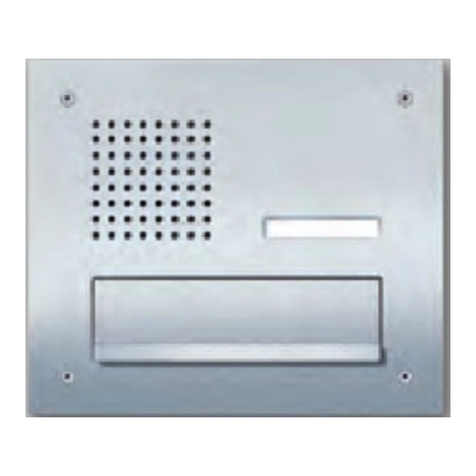
SSS Siedle Classic CL 111 B-02 Series Product information
LEGRAND
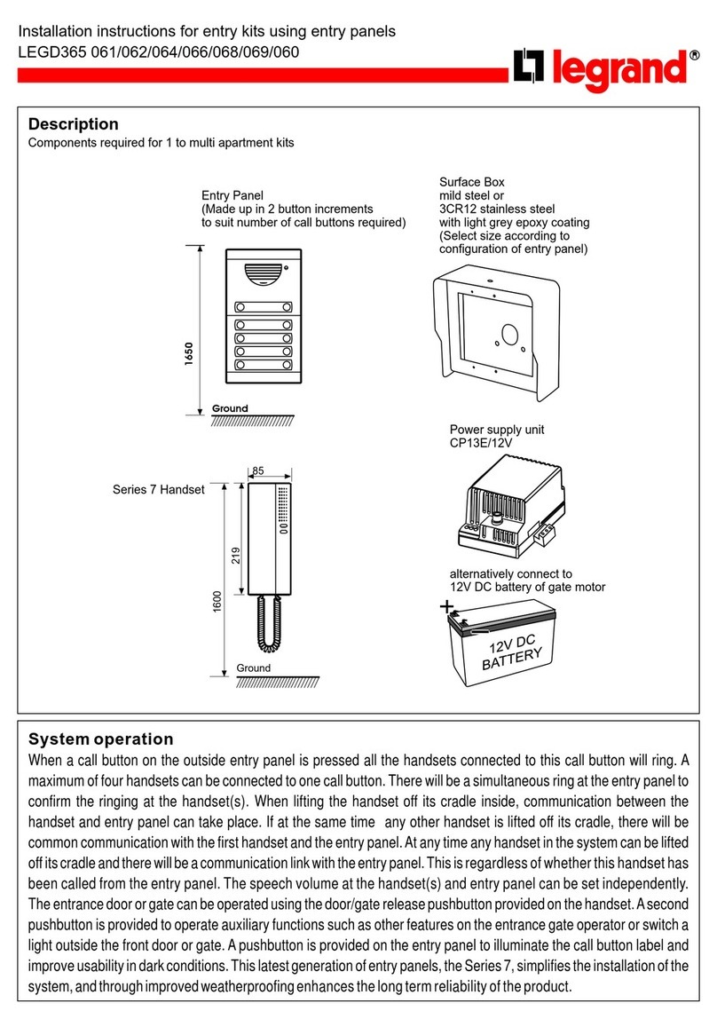
LEGRAND LEGD365 061 installation instructions
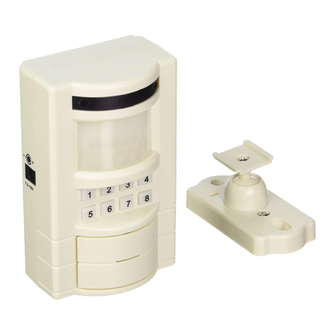
Carlon
Carlon HS4320D Instruction guide
SSS Siedle
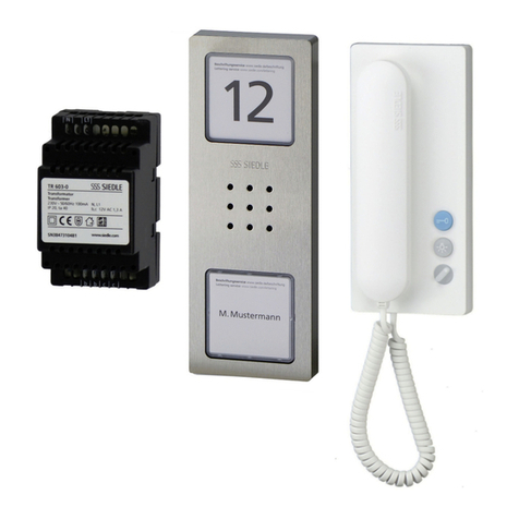
SSS Siedle Compact SET CA 812-1 E/W Product information
