ECA OASIS Assembly instructions

Page 1of 3
9065-0099 Rev H
OASISTM & OASISTM MINI
Table Trough Installation Sheet
ECA • 10 Mountain View Drive • Shelton, CT 06484 • Phone: 1-800-521-3175 • Fax: 203-924-6687
www.electri-cable.com
Cutout
Width *
Cutout
Length
Clamp & Thumb Screws
2 Sets
Double Sided Adhesive Tape
Not Su
pp
lied
CUTOUT SIZES
Oasis Oasis Mini
Cutout 8.25 8.25
Width*
Cutout 29.12 14.12
Length
* See Cutout Detail for undercuts
required for door clearance.
Removable
Inserts
OASIS
TM
Pan
FIGURE 1
FIGURE 2
Thumb Nut & Washer
2 Per Insert
Innovative Power + Data Solutions
Page 2of 3
9065-0099 Rev H
Installation Instructions
1. Cutout table as required (see Figure 1, Cutout Sizes & Cutout Detail)
2. Insert OASISTM into cutout from above and clamp into position using Clamps & thumb
Screws provided. Note: Keyslots in clamps engage over T-Studs in OASIS™ and thumb
screws tighten against underside of table surface. (double sided tape may be required
to prevent side of Bezel from bowing when in table).
3. Check for smooth operation of doors and adjust in cutout if required.
4. OASISTM Inserts have been installed at the factory but may be repositioned in the field if
desired. To reposition OASISTM Inserts remove thumb nuts & washers from rear and
reposition as needed (see Figure 2).
5. Connect all power & data cabling as needed and check for proper operation.
6. Attach Outer Pan (optional) to underside of table as shown in Cutout Detail.
ECA • 10 Mountain View Drive • Shelton, CT 06484 • Phone: 1-800-521-3175 • Fax: 203-924-6687
www.electri-cable.com
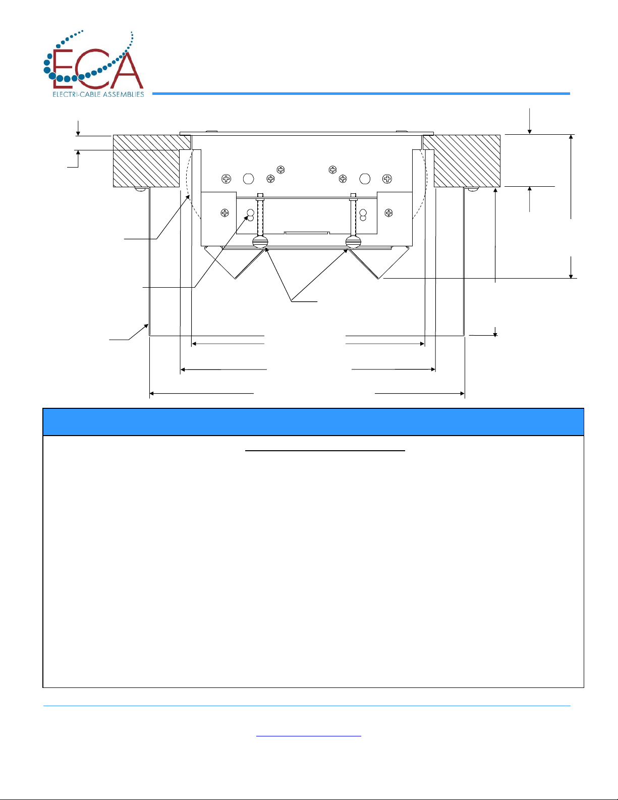
CUTOUT DETAIL
9.00 Clearance
.50
Both
Sides
Cutout Width *
Door Swin
g
Outer Pan
(Optional)
Table
Thickness
1.25 – 2.00
11.20 Outer Pan Width
5.28
Outer Pan
Depth
Keyslots Engaged
Over T-Studs Thumb
Screws
Corded = 4.90
Sys 42 = 5.85
Innovative Power + Data Solutions

Page 3of 3
9065-0099 Rev H
ECA • 10 Mountain View Drive • Shelton, CT 06484 • Phone: 1-800-521-3175 • Fax: 203-924-6687
www.electri-cable.com
Innovative Power + Data Solutions
This manual suits for next models
1
Table of contents


