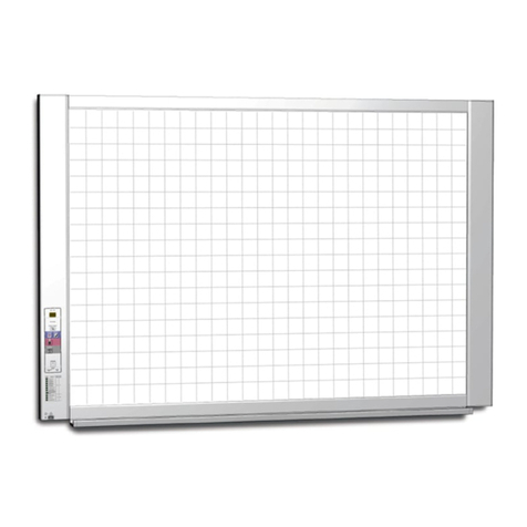
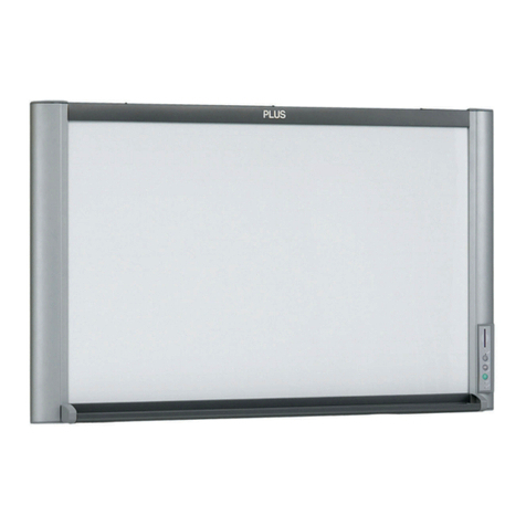
Plus M-10S User manual

COPY BOARD
M-10S/M-10W
SERVICE MANUAL

1.COMPLIANCE OF SAFE REPAIR ................................ 1
1-1. Cautions during Product Movement .......................... 1
1-2. Cautions during disassembling and assembling ........ 1
2.SPECIFICATIONS ......................................................... 2
2-1.Product Specifications ................................................ 2
2-2. Location of Parts and Controls .................................. 3
2-3. Operation Panel of Main Unit ..................................... 4
2-4. Error Display .............................................................. 6
3.TROUBLE SHOOTING.................................................. 7
4.DISASSEMBLY AND ASSEMBLY ................................ 8
4-1.Tools Required ............................................................ 8
4-2.Caution ....................................................................... 8
4-3.Disassembly and Assembly Procedures ..................... 8
4-4.Disassembly and Assembly ........................................ 9
CONTENTS
5. ADJUSTMENT .............................................................. 15
5-1. CCD Adjustment ........................................................ 15
5-2. Calibration .................................................................. 21
5-3. Tension Adjustment of Timing Belt ............................. 23
6. Cable and Cable connection ...................................... 24
7. PARTS LIST ................................................................ 25
1. Overall configuration ..................................................... 25
2. Frame Cover Section .................................................... 27
3. Sheet Frame Section .................................................... 29
4. Board Frame Section .................................................... 31
5. Accessories Section ...................................................... 33
6. Carton & Packing .......................................................... 35
7. Screws & Washers ........................................................ 37
8. M-10-T........................................................................... 38
8. REVISION HISTORY .................................................... 40

1
1. COMPLIANCE OF SAFE REPAIR
Be sure to read this Service Manual before providing services. In the PLUS Copyboard, full consideration is
taken to ensure the safety for a fire, electric shock, injury, harmful radiation, and substance. Therefore, observe
the notice described in this Service Manual so that the safety is kept when providing services. Moreover, be sure
to observe the notice described in the Instruction Manual.
Pay attention to the following during service inspection.
1-1. Cautions during Product Movement
• It is necessary to remove the products when making the service of products put on the wall. At that time, hold
the products by two or more persons to prevent the products from dropping or a person from falling down.
1-2. Cautions during disassembling and assembling
1. This equipment contains parts under high voltage. When doing repairs, make sure that power plug is pulled
out to insure safety.
2. Make sure that parts and screws and wiring, etc. are returned to their original positions. Tube, tape and
other insulation materials have been used for safety reasons. The internal wiring has been designed to
avoid direct contact with hot parts or parts under high voltage when using clamps or other tools.
3. The parts used in this device have special safety features such as flame-resistance and anti-voltage proper-
ties. When replacing parts, always use parts supplied from the factory.
4. After finishing operations make sure that all parts and wires have been returned to their original position and
that there has been no deterioration of the area around the location that was worked on.
5. Be sure to use an earth band (wrist band) during repair and inspection.

2
2. SPECIFICATIONS
MODEL NAME
Panel Size
Copy Area
BOARD Number of Pages
Paglng
Grid Line
Image Sensor
Type of printer
PRINTER Paper
(Optional) Colors
Interface
MEMORY
Type of Memory Card
File Format
Buttons
CONTROL PANEL
LED Indicators
SAFETY Safety Agencies
TANDARD EMC
ENVIRONMENTAL
Power
CONDITION
Temperature
Humidity
DIMENSIONS
Dimensions (with Stand)*6
Weight (without Printer)
MOUNTING
ACCESSORIES
2-1. Product Specifications
M-10S M-10W
920 (H) ✕ 1300 (W) mm 920 (H) ✕ 1800 (W) mm
850 (H) ✕ 1240 (W) mm 850 (H) ✕ 1740 (W) mm
2
Motorized (Forward) & Manual (Forward & Reverse)
50 ✕ 50mm
CCD Optical Sensor
Inkjet (HP PCL Level 3 Compatible) *1
Plain Paper, A4-size / Letter-size
4-color (Black,Red,Blue,Green) or Black
USB 1.1 equivalent
CompactFlash Card (CF Card) TYPE I,TYPE II *2
PNG *3
Power
Mode
Copy
Repeat *4
Memory
Feed/Stop
Density
Memory Card
Color
Density
Clear OK
Counter Display
TUV,CE,UL/cUL,AS *5
CE,FCC,C-Tick Mark *5
100V, 110V, 120V, 220V-240 V *5
10-35°C
30-85 % (non-condensing)
1470 (W) ✕ 600 (D) ✕ 1970 [max](H) mm 1970 (W) ✕ 600 (D) ✕ 1970 [max](H) mm
36 kg 40 kg
Stand / Wall-mount
AC Cable for M-10,USB Cable (Printer),Markers (Black, Red, Blue, Green),Eraser,
Wall mounting hooks and screws, Operation Manual, Set-up Manual, Paper (10
sheet)
Remaeks
*1: A Printer is not included in the package.
*2: A CompactFlash Card is not included in the package.
*3: The PNG format is supported by Microsoft internet Explorer 4.0 or later,and by Netscape Navigator 4.04 or
later.
*4: The maximum repeat is 20 copies.
*5: The condition is subject to change dependes on sales area.
*6: the height is adjustable at 1770,1879 and 1970 mm.

3
SPECIFICATIONS
2-2. Location of Parts and Controls
Front panel of main unit
35mm
35mm
35mm 35mm
Figures or characters are drawn in this sheet
using a dedicated marker. (Section paper of 50
x 50 mm is not copied.)
Thiscardslotisthesectionintowhich
a
compactflashcardisinserted.
Aprinterisputinthisprinterstand.
Thisdimensionalsectiononthesheet
planeisnotreadduringcopy.Drawa
figureintheeffectivereadrange.
Effective read size
Tray
Copyboard
Sheet
Card Slot
Operation Panel
Printer Stand

4
SPECIFICATIONS
Front panel of main unit
Printer connector
Connect this with the USB connector of the printer.
(The printer connector is dedicated for use with a
printer; use it only with a printer.)
Some models have the AC
OUTPUT
connector depending
on the country of destination.
The connector is located on
the bottom surface of the
copyboard. The diagram view
is seen from the bottom.
AC input connector
This connector supplies power to the
copyboard. Make a connection between
this and an AC wall power outlet.

5
SPECIFICATIONS
2-3. Operation Panel of Main Unit
MEMORY
COPY
OK Cancel
REPEAT
Density
FEED/STOP
MemoryClear
COLOR
POWER
M-10
During button operation, press the center (round con
vex se-
ction) of the button. Do not press the corner of
the button.
No function operates in this case.
1 POWER button (Power supply)
Press this button to turn on and off the power of
the copy
board.
2 COLOR button (Color)
Press this button to select whether to print a sheet in
"color" or "monochrome".
The Color lamp lights when you select "color".
*
When a monochromatic printer has been conne
cted, a
sheet is printed in monochrome even if you select "color".
3 Color (color mode) lamp
This Color mode lamp lights in green when you select
"color" using a Color button.
4 +/- button (Setting of printed sheet count)
Press the + or ? button to set the number of printed sheets.
(The maximum number of printed sheets is 20.)
The number of printed sheets appears on the display
window.
5 Display window
The printed sheet count, print density, memory storage
operating state, or error information is notified using
seven-segment LED. See page 22 for details of the error
information.
6 COPY button (Print)
The sheet is moved for read operation by one plane and
printed proportionally to the number of printed sheets.
7 MEMORY button (Memory storage)
The sheet is moved for read operation by one plane and
stored in a compact flash card.
8 REPEAT button (Repeat)
The previously printed sheet plane is printed once again.
(The sheet is not then moved.)
The number of printed sheet can be changed, but the density
and color/monochrome cannot be changed.
9 FEED/STOP button (Feed/Stop)
The sheet is scrolled to the left by one plane and stopped
a
utomatically. The scroll stops when you press this button
during scrolling.
10 Density button (Copy density)
Press the Density button to select "Standard" or "Dark" as
the density of a print. The Density lamp lights when you
select "Dark".
11 Density (density mode) lamp
This density lamp lights in green when you select "Dark"
using a Density button.
12
Memory Clear button
(Overall compact flash card clear)
The Clear mode lamp blinks when you press the Memory
Clear button. (The maximum number of files ("max 99")
blinks and appears on the display window.)
All data in the PVW folder of a compact flash card is cleared
when you press the OK(+) button.
Press the "Cancel" (-) button when you do not want to clear
all data. The display window returns to the display of the
printed
sheet count.
13 Clear (clear mode) lamp
This Clear mode lamp lights in orange when you press the
Memory Clear button and when the unit is put into the clear
mode.
4
7
9
12
3
2
1
10
11
8
6
13
5

6
SPECIFICATIONS
2-4. Error Display
Confirm the contents of the table shown below when E1 to E6 and the
blink display (blinks for ten seconds) appear on the display window of
the operation panel.
Error display number
E1
Printer failure
E2
Memory card not
recognized
E3
Defective memory
storage
E4
Defective memory
clear
E5
Read failure
E6
Internal memory
failure
Description
•A printer cable is not connected.
•The power of a printer is not turned on.
•Paper is not put in a printer.
•The error lamp of a printer blinks.
•A memory card is not formatted.
•An incompatible memory card is used.
•A CF adaptor is not properly inserted when it
is used.
•A memory card is defective.
•An error occurred during memory storage.
•An error occurred during memory erasure.
•A fluorescent lamp does not light properly.
•A read signal error occurred.
•A memory read/write error during internal
memory initialization occurred when the
power plug is inserted into the wall outlet.
Remedy
•Check the connection of a printer.
•Check the power of a printer.
•Check the paper in a printer.
•See the Instruction Manual of a
printer.
•Format the memory card using a
personal computer.
•Browse our homepage for the
memory card and CF adaptor that
can be used in this unit.
(http://www.plus-vision.com)
•Check that the CF adaptor is in-
serted properly.
•Check the operation using a per-
sonal computer.
•Check that a memory card is not
removed or inserted during stor-
age.
•Repeat storage again.
•Main Board Assy is defective.
•Check that a memory card is not
removed or inserted during stor-
age.
•Repeat storage again.
•Main Board Assy is defective.
•Turn off the power once, turn on it
again, and perform the copy opera-
tion.
•A fluorescent lamp reached its life
span or it is defective.
•The CCD Board Unit is defective.
•Adjust the CCD read position.
•Pull out the power plug from the wall
outlet and insert it into the wall out-
let again.
•Main Board Assy is defective.
MEMORY
COPY
OK Cancel

7
By checking operations normal usage time, it is possible to carry out judgments on malfunction to a certain extent. Carry out the following
checks before disassembling the equipment.
1. Press the POWER button and turn on the power.
Is the power turned on?
No •The power cord is disconnected from the wall outlet.
•The Power Unit is defective.
•The Main Board Assy is defective.
•The Switch Board Assy is defective.
•The connector of the Secondary Side Power Harness is disconnected.
•The connector of the Switch Harness is disconnected.
Yes
Does the error display appear?
Yes The error display (E5) appears. (See 2-4 Error Display.)
•The Fluorescent Lamp reached its life span or it is defective.
•The connector (CN4) of the Lamp Socket Unit is disconnected or it is defective.
•The connectors (CN11 and CN1) of the CCD Harness Assy is disconnected.
•The CCD Board Unit is out of adjustment.
•The CCD Board Unit is defective.
•The Main Board Assy is defective.
The error display (E6) appears. (See 2-4. Error Display.)
•The Main Board Assy is defective.
No
2. Press the FEED/STOP button.
Does the sheet operate normally?
No •The connector of the Motor Harness is disconnected.
•The Timing Belt is disconnected or loosened.
•The Sheet Motor Assy is defective.
•The Main Board Assy is defective.
Yes
3. Press the COPY button (when a printer is used).
Does the error display (E1) appear?
Yes Printer failure (See 2-4. Error Display.)
•The printer is defective. (See the Instruction Manual of a printer.)
•The power of a printer is not turned on.
•The paper of a printer is exhausted.
•The printer is not connected.
•The Main Board Assy is defective.
No
Is the object written in the board printed normally?
No A black line is put in printing.
•The Fluorescent Lamp deteriorates.
•Out-of-adjustment of CCD Board Unit: Slight (It is improved by calibration. See section 5-2.)
•Out-of-adjustment of CCD Board Unit: Severe (Perform the CCD adjustment again. See section 5-1.)
•Dust adheres to the mirror of the board body.
Printing becomes blurred.
•The Fluorescent Lamp deteriorates.
•The marker (written character) becomes blurred
•The ink (toner) of a printer is exhausted.
A specific color is not printed or the printed color is improper (when a color printer is used).
•The ink of a printer is exhausted.
•The ink cartridge of a printer is defective.
Yes
4. Press the MEMORY button (when a compact flash card is used).
Do the error displays (E2 and E3) appear?
Yes Error display: E2 is displayed. (See 2-4 Error Display.)
•A memory card is not formatted.
•An incompatible memory card is used.
•A memory card is defective.
•Insertion failure (when a CF adaptor is used)
Error display: E3 is displayed.
•Memory storage error: Repeat storage again.
•The Main Board Assy is defective.
No
Is the object written in the board stored normally?
No A black line is put in a picture.
•The Fluorescent Lamp deteriorates.
•Out-of-adjustment of CCD Board Unit: Slight (It is improved by calibration. See section 5-2.)
•Out-of-adjustment of CCD Board Unit: Severe (Perform the CCD adjustment again. See section 5-1.)
•Dust adheres to the mirror of the board body.
A picture becomes blurred.
•The Fluorescent Lamp deteriorates.
•The marker (written character) becomes blurred.
Yes
Normal operation
3. TROUBLE SHOOTING
8
4. DISASSEMBLY AND ASSEMBLY
4-1. Tools Required
•Phillips screwdriver No. 2
•Cutting pliers
•Electrostatic elimination wrist band
4-2.Caution
•See “1. Compliance of Safety Repair and Safety Inspection”before disassembling and assembling.
•Put on gloves so that you do not cut your hand at the sharp edge of a frame during disassembly and assem-
bly.
•See “6. Wiring Diagram”and “7. Parts List”for the parts name or wiring.
•The point especially requiring attention when handling parts or performing disassembly and assembly con-
tains a caution. Be sure to follow this caution.
4-3. Disassembly and Assembly Procedures
START
Power Unit
CCD Board Unit
Back Panel
Fluorescent Lamp
Main Board Assy Frame Cover Unit
Endless Sheet
Sheet Motor Assy
Lamp Socket Unit
Switch Board Assy
Sheet Frame Unit

9
DISASSEMBLY AND ASSEMBLY
2) Remove the Main Board Assy. (See Figs. 3, 4, and 5.)
1. Disconnect the connectors (CN2, CN6, CN10, and
CN11) connected to the Main Board Assy shown in
Fig. 3.
2. Remove the “S-12”screw shown in Fig. 4 and then
remove the Main Board Section.
3. Remove the “S-7”screw shown in Fig. 5 and then
remove the Main Board Assy.
4-4.Disassembly and Assembly
This section describes one example of disassembly and assembly procedures. For the actual operation,
disassemble and assemble the required parts with reference to “4-3. Disassembly and Assembly Procedures”.
1) Remove the Back Panel. (See Figs. 1 and 2.)
1. Remove the “S-1”screw shown in Fig. 1 and then remove the Back Panel Corner.
2. Remove the Back Panel as shown in Fig. 2.
Fig. 1
Fig. 2
Fig. 4 Fig. 5
S-1
BackPanelCorne
r
BackPane
l
CN10
(16pin)
CN2
(6pin)
CN6
(9pin)
CN11
(20pin)
S-12 S-12
MainBoardSection
S-7
S-7
MainBoardShiel
d
MainBoardAssy
MainBoardBox
Fig. 3

10
DISASSEMBLY AND ASSEMBLY
3) Remove the Power Unit. (See Figs. 6, 7, and 8.)
1. Remove the PU Cover B shown in Fig. 6. (The PU
Cover B is attached using a double-coated tape.)
2. Disconnect the connectors (CN3 and CN9) con-
nected to the Power Unit shown in Fig. 7.
3. Remove the “S-9”screw shown in Fig. 8 and then
remove the Power Unit.
Notes:
•Connect connectors (CN3 and CN9) before install-
ing the PU Cover B.
•A toothed washer (S-13) is put in the screw on the
inlet side when the Power Unit is installed.
Fig. 9
Fig. 6
Fig. 7
Fig. 8
4) Remove the CCD Board Unit. (See Fig. 9.)
1. Remove the “S-4”screw shown in Fig. 9 and then
remove the CCD Board Unit.
Note:
The CCD Board Unit requires adjustment when it is
replaced and removed. (See 5. Adjustment.)
PUCoverB
CN4
(4pin)
CN3
(9pin)
S-9
S-13
S-9
PUPlateB
PUPlate
A
PowerUn
it
S-4
S-4
CCDHarnessAssy
CCDBoardUnit

11
DISASSEMBLY AND ASSEMBLY
Fig. 10
Fig. 11 Fig. 12
5) Remove the Frame Cover Section. (See Fig. 10.)
1. Remove the “S-11”and “S-10”screws shown in Fig. 10. The S-12 screw is removed only when the Main
Board Assy is not removed. (Remove the connector connected to the Main Board Assy.)
6) Remove the Switch Board Assy. (See Fig. 11.)
1. Remove the “S-10”screw shown in Fig. 11.
2. Remove the “S-6”screw shown in Fig. 11 and then remove the Switch Board Assy.
Note:
Be careful not to mistake the hole through which the Switch Harness is passed. (See Fig. 12.)
S-11
S-11
S-12
CapL
CapL
CapR
CapR
S-6
S-10
SWBoardAssy
SwitchHarness
SwitchHarness
[FrontSide] [OtherSide]

12
DISASSEMBLY AND ASSEMBLY
Fig. 13
Fig. 14 Fig. 15
7) Disassemble the Frame Cover Section. (See Fig. 13.)
Remove the “S-2”and “S-7”screws shown in Fig. 13 and disassemble the frame cover.
8) Remove the Sheet Frame Unit. (See Figs. 14 and 15.)
1. Remove the “S-2”screw shown in Fig. 14.
2. Remove the Sheet Frame Unit as shown in Fig. 15.
Note:
The Sheet Frame Unit is caught on a hook as shown in the portion A of Fig. 14.
S-2
S-2
S-2
S-2 S-2
S-2
S-2
S-7
S-7
S-2
S-2
S-2
CoverPlate
CoverPlate
CoverPlat
e
CoverPlat
e
FramCoverUpper
FramCoverSideL
FramCoverLowerUnit
FramCoverSideR
CoverL
CoverR

13
DISASSEMBLY AND ASSEMBLY
Fig. 19
Fig. 16
Fig. 17
Fig. 18
9) Remove the Sheet Motor Assy. (See Fig. 16.)
1. Remove the “S-4”screw shown in Fig. 16.
Note:
Adjust the tension of the Timing Belt when the Sheet
Motor Assy is installed. (See 5. Adjustment.)
10) Remove the Endless Sheet. (See Figs. 17, 18, and 19.)
1. Push the sheet roller section inside as shown in Figs. 17 and 18.
2. Remove the Endless Sheet as shown in Fig. 19.
Note:
•Be careful not to damage or fold it when handling the Endless Sheet.
S-4
SheetMotorAssy
MotorHarness
EndlessSheet
EndlessShee
t

14
DISASSEMBLY AND ASSEMBLY
Fig. 20
Fig. 21
11) Remove the Fluorescent Lamp. (See Fig. 20.)
1. Rotate the Fluorescent Lamp as shown in Fig.
20 and remove it from the lamp socket.
Note:
Be careful not to knock it against a frame and dam-
age it when the Fluorescent Lamp is installed and
removed.
12) Remove the Lamp Socket Unit. (See Fig. 21.)
1. Remove the “S-5”screw shown in Fig. 21 and
then remove the Lamp Socket Unit.
2. The Lamp Socket Unit is fixed to the board frame
using a cable tie. Therefore, the cable tie is re-
moved using cutting pliers.
Note:
Fix it using a cable tie again when installing the
Lamp Socket Unit.
FluorescentLamp
S-5
S-5
LampSocketUnit

15
5. ADJUSTMENT
5-1. CCD Adjustment
Adjustment is required in the following cases. (Calibration operation is also required after adjustment.)
•When a CCD Unit is replaced
•When adjustment got out of order due to the failure during arrival of products
•When the picture quality deteriorates remarkably
Calibration operation is required in the following cases.
•When a fluorescent lamp is replaced
•When the main board is replaced
•When the picture quality deteriorates slightly (The deterioration in picture quality may not be improved.)
Preparation
•Oscilloscope •Screwdriver (+) •Scale
Turn ON the power of an oscilloscope. Clean the plate surface.
* Insufficient cleaning influences the subsequent calibration. Color irregularity may sometimes occur in this
case.
CCD adjustment procedure
1) Remove the back panel. (See 4. Disassembly and Assembly.)
2) Connect the probe of an oscilloscope to the CCD Board.
(See the table below and the figure on right.)
Setting of oscilloscope
* The trigger corresponds to EXT or Ch2.
Only Ch1 is displayed.
GND Measurement pin
Ch1 J6 J4
Trigger or CH2 J8 J7
J5 J4
J3
J8 J7 J6
Mode
Ch1 0.5 V/DIV AC
Trigger 2 V/DIV DC
Sweep 500 µs/DIV

16
ADJUSTMENT
3) Focus adjustment of Lens Unit (See Figure 1.)
Fix the screw
4
tentatively so that the clearance between the Lens Unit and holder is 1.7 mm.
4) Clean the plate surface and then write an adjustment pattern. (See Figure 2.)
(Clean the plate surface sufficiently. If not, the subsequent calibration cannot be performed accurately.)
As shown in Figure 2, write the adjustment pattern using a black marker.
Write three horizontal lines of 100 mm long in the upper, middle, and lower positions according to the rule.
Write a vertical line of 100 mm long in the center 100 mm away from the middle position.
Note:
Write the horizontal lines in the upper and lower positions so that they are put in the rule.
4
1.7
Fig.1
Details
Fig.2

17
ADJUSTMENT
5) Put the set into the adjustment mode.
•Turn OFF the power.
•Press both the “+”and “Density”keys.
•Release the “+”and “Density”keys.
•Press the “Color”key.
•Confirm that the numeric LED display is 00.
•Press the “Repeat”key.
•The florescent lamp lights after four seconds and the set enters the CCD adjustment mode.
•Press the “Repeat”key.
•Confirm that the fluorescent lamp lighted.
•Confirm that the numeric LED display is 54.
6) Adjustment of oscilloscope (See Figure 3.)
Adjust the trigger level and Ch1 vertical position so that a CCD waveform appears on the oscilloscope display.
Adjust the horizontal position, luminance, and focus.
Fig.3

18
ADJUSTMENT
7) Right-and-left swing adjustment of CCD Unit (See Figures 4 and 5.)
As shown in Figure 5, insert a scale from the outer frame by 12 mm. Move plate B shown in Figure 4 from the
state where the edge of a scale is not displayed on the oscilloscope and fix screws ➄in Figure 4 when the level
fell into the intermediate position as shown in Figure 6.
B
5
12
Fig.4 Fig.5
Fig.6
Details
This manual suits for next models
2
Table of contents
Other Plus Office Equipment manuals

Plus
Plus N-21S User manual

Plus
Plus M-5 User manual

Plus
Plus N-32S User manual

Plus
Plus M-18S User manual

Plus
Plus M-125 User manual

Plus
Plus M-18S User manual

Plus
Plus N-20S User manual

Plus
Plus N-204S User manual

Plus
Plus N-20 Series User guide

Plus
Plus N-21 Series Installation and maintenance instructions
Popular Office Equipment manuals by other brands

Plustek
Plustek OPTICFILM 7400 - brochure

ECA
ECA OASIS Installation sheet

Count
Count EZCREASER user manual

Industrial Products
Industrial Products Public Protection Armor Boss ABX-4824 Installation Instructions and Maintenance Manual

OLG
OLG Axis/Anvil System installation guide

MEAVO
MEAVO CAMDEN MEETING POD owner's manual