6
Tattoo™ Screens - Spine Screen Leveling & Connecting
Assembly Instructions
Leveling & Connecting Spine
Screens
Note: A single Spine Screen may
not be used as a freestanding screen
on its own. The Spine Screen must
always be mechanically attached
to another Spine Screen (with or
without electrical).
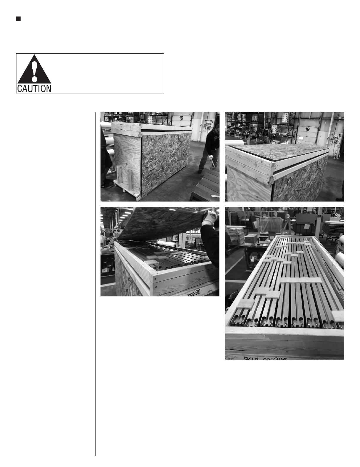
1. Check to make sure all
height-adjustable glides are
adjusted so the screens are at their
lowest position as illustrated in
Detail F on page 8. If glides are not
adjusted down fully to the bottom of
the screen, reference “Spine Screen
Foot Assembly” instructions on
page 5, step 3.
2. Carefully turn Spine Screens to the
upright position, and move to their
final installation location in-line to
each other per the space-planning
layout (Figure 2).
Important: Know and mark all high
and low spots on the floor. Make sure
to twist adjustable glides appropriate
to floor conditions. Always begin
assembling screens together at the
highest point of an un-even floor.
Note: If in-line Spine Screens
include change-of-height screen(s),
go now to “Leveling and Connecting
Change-of-Height Spine Screens”
instructions on page 8.
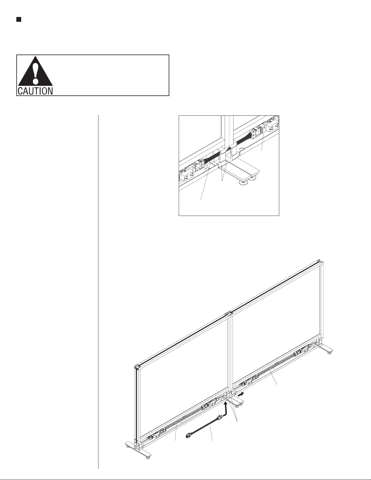
Using a laser alignment tool,
determine and mark all high and
low points on the floor. Adjust the
level and height of the Spine Screen,
beginning at the highest point in the
floor first. To raise the screen, rotate
the glide counter-clockwise. To lower
the screen, rotate the glide clockwise.
Only extend the glides as needed
to make the screen level and plumb
(Figure 2).
Note: If an in-line infeed power pole
or spacer is specified between two
screens, it must be installed between
the designated screens before
connecting the screens. If an in-line
10-wire top infeed power pole is to
be installed, reference “10-Wire Top
Power Infeed (In-Line) Installation”
Assemble units as described herein only. To do otherwise
may result in instability. All screws, nuts and bolts must be
tightened securely and must be checked periodically after
assembly. Failure to assemble properly, or to secure parts
may result in assembly failure and personal injury.
Spine Screen
(first)
Spine Screen
(second)
height-adjustable
glides (adjusted for
panels to be in the
lowest position)
(adjusted for the
panel to be in the
lowest position)
laser
alignment
tool
2
molding
clips
bottom
screen
connector
Detail C
bottom
screen
connector
molding clip
(come installed
from factory)
vertical
frame
channel
Spine
Screen
Spine
Screen
instructions on page 14. If an
in-line 10-wire top infeed power pole
is to be installed with a Flex Screen
intersection, reference “10-Wire Top
Power Infeed (In-Line) Installation
with Flex Screen Intersection”
instructions on page 16. If an
in-line 10-wire base infeed spacer is
to be installed, reference “10-Wire
Base Power Infeed Spacer (In-
Line) Installation” instructions on
page 24. If an in-line 10-wire base
infeed spacer with a Flex Screen
intersection is to be installed,
reference “10-Wire Base Power
Infeed Spacer (In-Line) Installation
with Flex Screen Intersection”
instructions on page 26. If an in-line
spacer is to be installed, reference
“In-Line Spacer Installation”
instructions on page 33. If in-line
spacer is to be installed with a
flex screen intersection, reference
“In-Line Spacer Installation with Flex
Screen Intersection” instructions on
page 34. After the spacer or in-line
infeed power pole has been installed,
proceed to step 4 on this page to
connect Spine Screens.
3. Locate the bottom screen connector
(Detail C) and take note that it
contains two molding clips installed,
one at each side. Figure 2 shows the
molding clips separated
for clarity. Each clip will press-fit
into the appropriate screen’s channel
to help join screens together.
Assure that the first Spine Screen
is level and plumb, and at its final
installation location. Position the
bottom screen connector up to the
bottom of the vertical channel of the
first Spine Screen and firmly press
it in, oriented as shown (Figure 2 &
Detail C).
4. Position the second Spine Screen
in-line against the first Spine Screen,
which has been adjusted level
and plumb. Level and plumb the
second screen to the first screen by
twisting the height-adjustable glides
clockwise or counter-clockwise until
the frame’s vertical edges are aligned
and tops of screens are at the same
height. Connect the screens together
by holding the first Spine Screen in
place while pressing firmly on the
second, into the first so the bottom
screen connector in the first engages
the second screen (Figure 2 &
Detail D).
5. Repeat the process in steps 4 & 5 to
add, level, plumb and connect the
remaining screens in the row. If the
remaining screens to be connected
are different heights, go now to
“Leveling & Connecting
Change-of-Height Spine Screens”
instructions on page 8, step 2.