Echelon IzoT U60 DIN User manual

005-1003-01A
Describes the IzoT U60 DIN Network Interface, a TP/FT-
10 channel type housed in a DIN 43880 2TE compliant
enclosure. Explains the two protocol processing modes
of operation, Layer 5 mode and Layer 2 mode
IzoT™ U60 DIN
Network Interface
User’s Guide

Echelon,LONWORKS, LON,LonTalk, Neuron, OpenLDV, IzoT, and the Echelon
logo are trademarks of Echelon Corporation that may be registered in the
United States and other countries. Other brand and product names are
trademarks or registered trademarks of their respective holders.
No part of this publication may be reproduced, stored in a retrieval system,
or transmitted, in any form or by any means, electronic, mechanical,
photocopying, recording, or otherwise, without the prior written permission of
Echelon Corporation.
Copyright © 2015 by Echelon Corporation.
All rights reserved.
Echelon Corporation
www.echelon.com

IzoT U60 DIN Network Interface User’s Guide
1
Contents
FCC Compliance Statement Class B 2
IC Compliance Statement, Class B 2
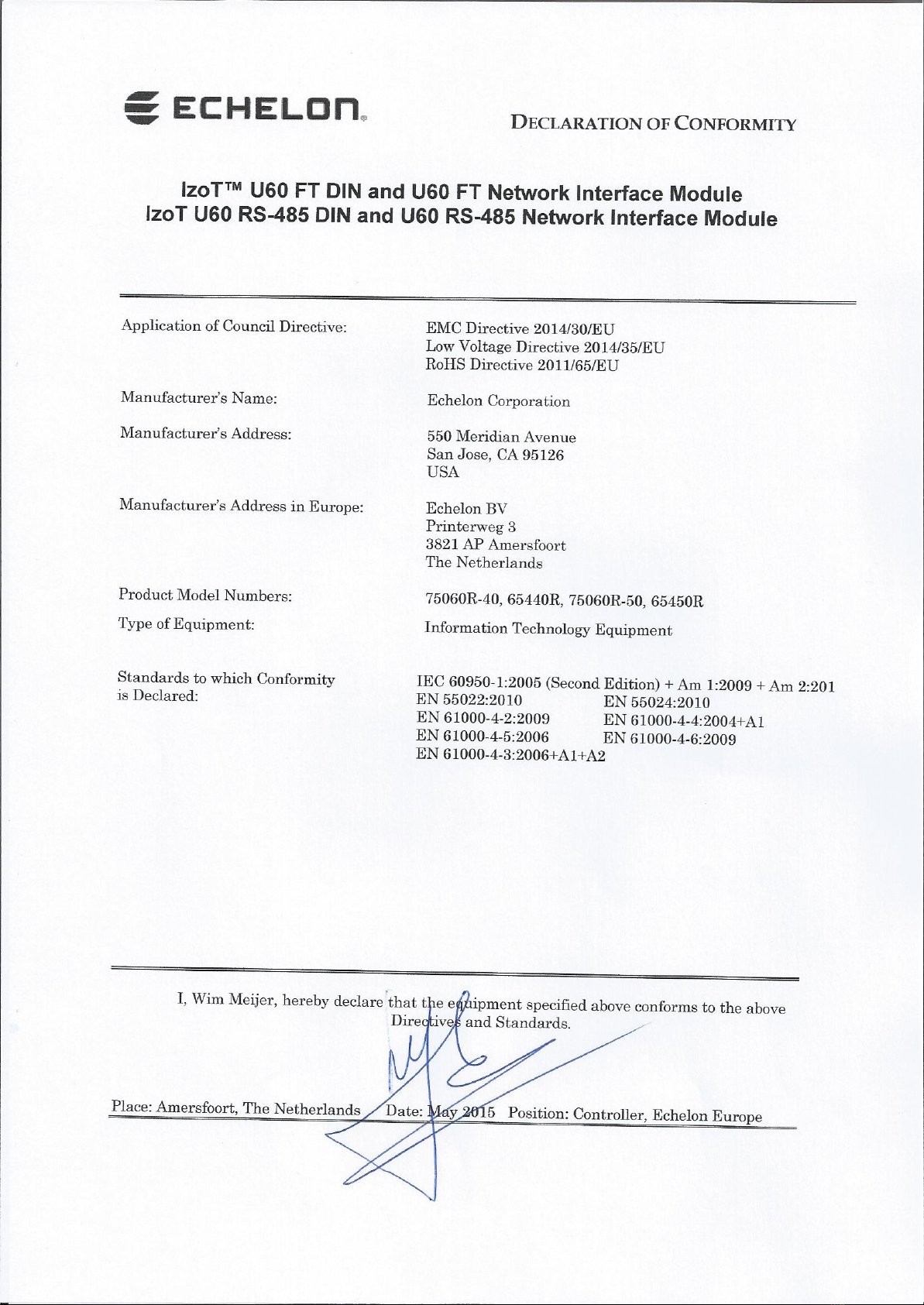
Declaration of Conformity 3
Related Documentation 4
Support 4
Introduction 5
Overview 6
Mechanical Dimensions 6
Visual Indicators 7
Connectors 7
Compatibility 8
Getting Started 9
Getting Started with the U60 for an IzoT Router 10
Getting Started with the U60 for a Windows Computer 10
Installing the OpenLDV™ 5 Software 10
Connecting the USB Network Interface 11
Using the LONWORKS®Interfaces Application 11
U60 Buffer Configuration 12
Testing or Resetting a U60 13
Removing a USB Network Interface 14
Getting Started with the U60 for Other Controllers and Hosts 15
Porting the U60 Drive 17
Porting the Linux U60 Driver 18
Host Communications 19
Protocol Processing Selection 20
Link Layer Protocol (LLP) 20
Type Code Values 23
Acknowledgement Rules 25
Sequence Number Cycling and Duplicate Detection 25
U60 Command Set 25
Product Query Network Management Command 27
Appendix A Troubleshooting Windows Computer Installations 29

IzoT U60 DIN Network Interface User’s Guide
2
FCC Compliance Statement – Class B
This equipment has been tested and found to comply with the limits for a
Class B digital device pursuant to Part 15 of the FCC Rules. These limits are
designed to provide reasonable protection against harmful interference in a
residential installation. This equipment generates, uses, and can radiate
radio frequency energy and, if no installed and used in accordance with the
manufacturer’s instruction manual, may cause interference with radio
communications. However, there is no guarantee that interference will not
occur in a particular installation. If this equipment does cause harmful
interference to radio or television reception, which can be determined by
turning the equipment off and on, you are encouraged to try to correct the
interference by one or more of the following measures: • Reorient or relocate
the receiving antenna. • Increase the separation between the equipment and
the receiver. • Connect the equipment into an outlet on a circuit different
from that which the receiver is connected. • Consult the dealer or an
experienced radio/television technician for help. Changes or modifications not
expressly approved by the party responsible for compliance could void the
user’s authority to operate the equipment.
IC Compliance Statement – Class B
This Class B digital apparatus meets the requirements of the Canadian
Interference-Causing Equipment Regulations of ICES-003.

IzoT U60 DIN Network Interface User’s Guide
4
Related Documentation
The following table lists related Echelon documentation that can be useful when using the U60
DIN Network Interface products. The latest versions of these manuals are available from the
Echelon website at: www.echelon.com/docs.
Title Part Number Description
OpenLDV™ Programmer’s Guide 078-0275-01D This document describes Echelon’s
OpenLDV Network Driver and
Software Development Kit (SDK)
Junction Box and Wiring Guideline
for Twisted Pair LONWORKS®
Networks
005-0023-01 This bulletin identifies the different
types of cabling and junction boxes
that may be used in twisted pair IzoT
and LON networks
IzoT Manual Available online at
www.echelon.com/docs/izot
This documentation describes how to
use the IzoT SDK, a software
development kit for the IzoT Platform.
It also describes how to use the IzoT
Router, a ready-to-run appliance for
connecting IzoT and LON devices on
an Ethernet channel with IzoT and
LON devices on an FT or RS-485
channel, and for connecting Web pages
and enterprise applications to IzoT
and LON devices.
Support
If you have technical questions that are not answered by this document, or by the
related documentation, you can obtain technical support via e-mail. Please contact
support@echelon.com.
See www.echelon.com/support for more information on Echelon’s support and
training services.


IzoT U60 DIN Network Interface User’s Guide
6
Overview
The U60 DIN Network Interface is a compact network interface for LonTalk/IP and
LON twisted pair communications. Two models are available, one for FT (ISO/IEC
14908-2 TP/FT-10) channels and one for RS-485 (TP/RS-485) channels. The U60
provides a USB interface for attaching to a host computer, controller, or router, or for
attaching to an Echelon IzoT Router. The U60 DIN Network Interface is packaged in
a DIN 43880 2TE compliant enclosure.
You can use multiple U60 DIN Network Interfaces with hosts such as the IzoT
Router that support multiple channels. When you attach multiple network interfaces
to a host, each U60 provides an interface to a single twisted-pair channel. You can
use up to four U60 DIN Network Interfaces with the IzoT Router to support routing
of up to five twisted-pair LON channels, one using the IzoT Router’s internal FT
network interface, and up to four additional channels with external U60 DIN
Network Interfaces.
The U60 has two protocol modes of operation—Layer 2 mode and Layer 5 mode that
can be selected by the host application.
In Layer 2 mode, the U60 implements Layers 1 and 2 of the ISO/IEC 14908-1 and
14908-2 protocol and is compatible with the LonTalk Device Stack EX included with
the IzoT SDK Standard and Premium Editions. The LonTalk Device Stack EX
provides source code for LonTalk /IP and classic LON compatible protocol stacks.
In Layer 5 mode, the U60 implements Layers 1 through 5 of the ISO/IEC 14908-1
and 14908-2 protocol and is compatible with Echelon’s previous generation
Microprocessor Interface Program (MIP) products.
When used with a Windows computer, the mode is typically selected automatically by
the application.
A Service LED indicates the network status of the U60, with Rx and Tx LEDs
providing an indication of packet reception and transmission.
The U60 DIN is powered through its USB interface.
Mechanical Dimensions
The U60 DIN 43880 2TE enclosure is 35mm (1.38“) wide, 89.5mm (3.52“) high and
66.5mm (2.62“) deep excluding the network connectors.
IzoT U60 DIN Network Interface User’s Guide
7
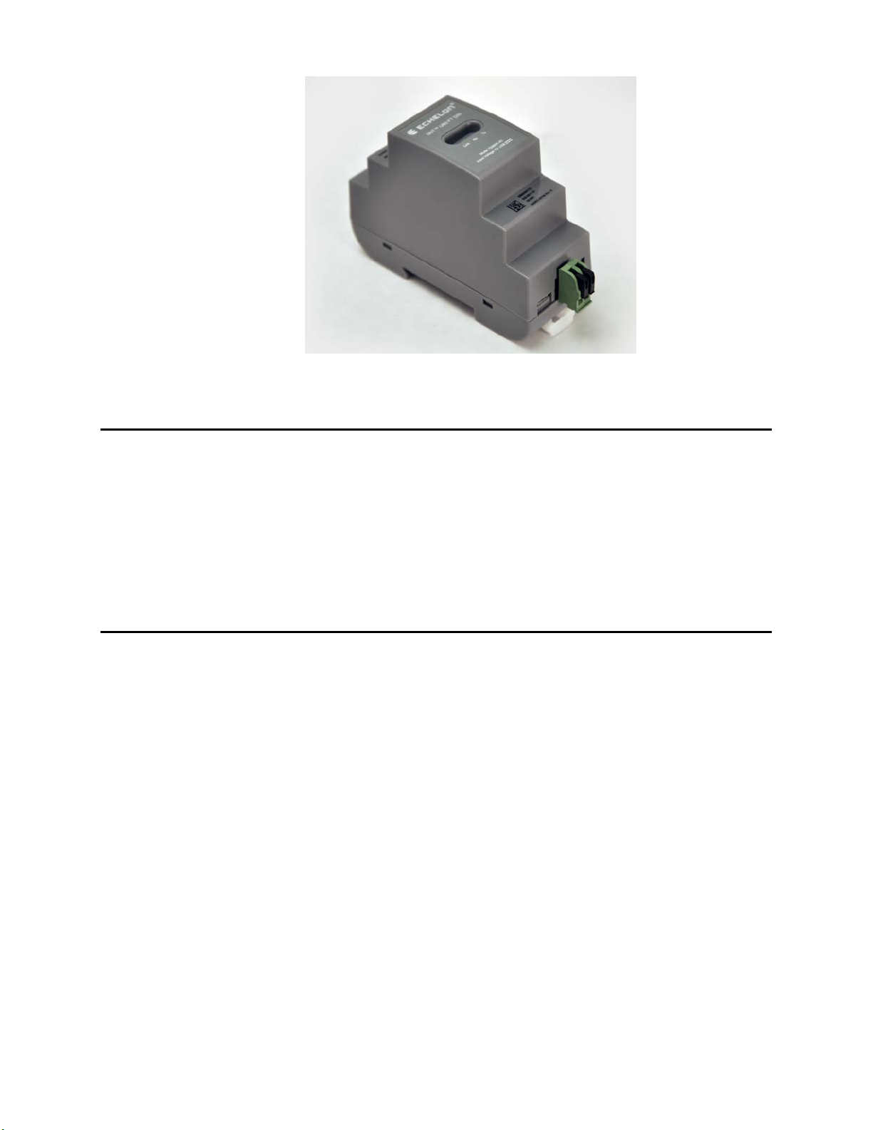
The U60 FT DIN
Visual Indicators
Three LEDs are located in the centre of the enclosure. The yellow Service LED on
the left (labelled Link or Service), provides a visual indication of the network status
of the U60. The RX LED in the middle flashes green when data is received from the
network. The TX LED on the right flashes green when data is transmitted onto the
network.
The Service status is also provided to the host via the USB interface so that the host
can provide a network Service indicator if required.
Connectors
The U60 FT DIN has a two-way network connector with push clips to retain the
network cabling. The network connection is polarity insensitive.
The U60 RS-485 DIN has a three-way network connector, also with push clips to
retain the network cabling. The three positions of the connector are used for the
following: +(Signal + or B), -(Signal - or A), and SC (Signal Common). When used in
unbiased LONWORKS RS-485 networks, the network connection is polarity
insensitive.
Both the U60 FT DIN and U60 RS-485 DIN also have Micro B female USB
connectors for connection to a host processor and come supplied with a suitable USB
Type A to Micro-B cable.

IzoT U60 DIN Network Interface User’s Guide
8
Compatibility
The U60 DIN is compatible with the IzoT Router, Windows computers with
OpenLDV 5, with hosts communicating with a Layer 5 MIP interface, and with hosts
communicating with a Layer 2 MIP interface including hosts implementing the IzoT
Device Stack EX.


IzoT U60 DIN Network Interface User’s Guide
10
Getting Started with the U60 for an IzoT Router
You can use the U60 DIN Network Interface to add connectivity to an additional FT
or RS-485 channel, in addition to the FT channel attached to the LON port of the
IzoT Router. You can add up to four additional external U60 DIN Network Interfaces
(either LON FT or LON RS-485) to the IzoT Router.
To add one or two external U60 interfaces, plug each U60 into one of the external
USB ports on the IzoT Router. To add three or four external U60 interfaces, plug
each U60 into a port of an external powered USB hub, and plug the USB hub into the
IzoT Router. Once you plug in a new U60, the IzoT Router takes a minute to
reconfigure itself. During this time Web page access may not be available. The IzoT
Router and U60 DIN Network Interface have been tested with the D-Line DUB-H7
and the Manhattan 10-port powered USB hubs. You can use any powered USB hub
that complies with the USB 2.0 standard.
When you add a new external U60 interface, the IzoT Router automatically creates a
LAN IP-70 to LON router for the channel attached to the U60 interface. The routers
available in an IzoT Router are listed on the IzoT Router System Web page, and you
can use the Service Pin buttons on this Web page to send Service messages for any of
the routers. If you are installing the IzoT Router in a managed network using a
network management tool such as IzoT CT or the LonMaker tool, you can install the
routers using your network management tool. If you have multiple U60 interfaces,
you can associate you physical U60 interfaces with the listed routers using the MAC
ID for the U60 interfaces. The MAC ID for the LON interface of each router is listed
in the LON column of the router table on the IzoT Router System Web page. The
MAC ID for each physical U60 is printed on a MAC ID label that is included with
each U60 interface. For easy reference, a 5-digit install code is also printed on the
label. The install code is the last 5 digits of the MAC ID, and provides a shorter
identifier than the 12-digit MAC ID.
You can add a Layer 5 or Protocol Analyzer Layer 2 remote network interface (RNI)
for the built-in FT interface and for any of your external U60 interfaces. See the
Using the RNI and IP-852 Network Interfaces topic in the online IzoT Manual at
www.echelon.com/docs/izot for more information.
Getting Started with the U60 for a Windows Computer
You can use the U60 DIN Network Interface to attach a computer running Microsoft
Windows to a LON network. To use a U60 with a Windows computer, install
OpenLDV 5, attach the U60, and configure the LONWORKS Interfaces application as
described in the following sections.
Installing the OpenLDV 5 software
The OpenLDV 5, or newer, driver is required to use a U60 with a Windows computer.
OpenLDV 5 is compatible with the IzoT Net Server, OpenLNS Server, and LNS
Server, and is also compatible with all IzoT Net, OpenLNS, and LNS applications and
tools including the IzoT Commissioning Tool(CT), OpenLNS CT, and LonMaker
Integration Tool. Install the OpenLDV 5 software before connecting the USB DIN
interface to your computer. You must have Administrator privileges on your
computer to perform the installation.

IzoT U60 DIN Network Interface User’s Guide
11
To install the OpenLDV 5 software, follow these steps:
1. Dowload OpenLDV 5 from here, run the installer and follow the instructions.
2. The OpenLDV 5 installer includes and automatically installs all required USB
driver files.
Connecting the USB Network Interface
After you have installed the OpenLDV 5 software, plug the U60 Network Interface
into your computer and connect to an FT or RS-485 channel.
To do so, follow these steps:
1. Connect the network cabling to the U60.
2. Insert the Micro-B USB plug of the supplied USB cable into the USB connector
on the USB DIN.
3. Insert the Type A USB plug of the supplied USB cable into an available USB port
on your computer.
4. If this is the only LONWORKS interface installed on your computer, it will
automatically LON1 as the default name, and you can proceed directly to your
software application and begin using the interface as LON1. If you have multiple
LONWORKS network interfaces, you can use the LonWorks Interfaces application
described in the next section to determine the name of each of your network
interfaces.
Using the LONWORKS Interfaces Application
You can use the LONWORKS Interfaces application to configure, test, reset, or
remove a LONWORKS USB interface. These procedures are described in the following
sections. The LONWORKS Interfaces application is in the Windows Control Panel
Each LONWORKS USB interface has a unique ID, and the LONWORKS Interfaces
application keeps track of each LONWORKS network interface plugged into a
computer, even after they have been detached from the computer. This means that
you can remove a particular USB interface from your computer and later reattach it,
and it will continue to use the same LONWORKS network interface name (e.g. LON1
or LON2) once you reattach it and it is recognized by your computer, regardless of
how many USB interfaces are plugged into your computer, or in which order. It also
means that each USB interface will retain the network interface name assigned to it,
even after it has been detached from your computer.
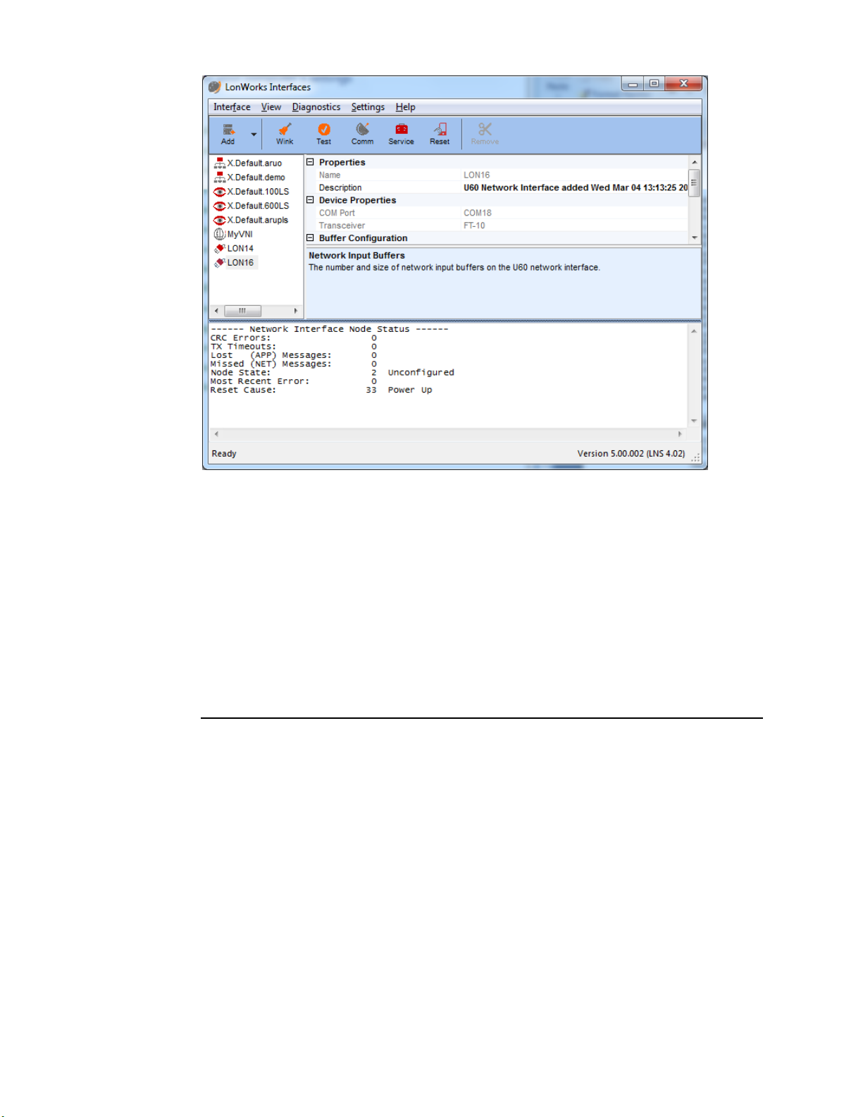
The following figure illustrates the LONWORKS Interfaces application windows with
a U60 FT DIN Network Interface selected.

IzoT U60 DIN Network Interface User’s Guide
12
The list of network interfaces in the left pane of the LONWORKS Interfaces
application is not automatically updated when you attach a U60 DIN Network
Interface to your computer. If you have the LONWORKS Interfaces application open
when you attach a U60, you can refresh the network interface list by selecting View-
>Refresh from the main menu, or by pressing F5. You can also close and re-start
the LONWORKS Interfaces application.
By default, detached LONWORKS USB interfaces are not displayed by the
LONWORKS Interfaces application. To see all LONWORKS USB interfaces, including
those that are currently detached, select View->Show Detached Interfaces from
the main menu. To free the logical name assigned to a network interface, remove the
definition as described in the Removing a USB Network Interface section below.
U60 Buffer Configuration
The following table summarizes the U60 network buffer counts and sizes:

IzoT U60 DIN Network Interface User’s Guide
13
Buffer Count Size (bytes)
Application Input 2 255
Application Output (non-
priority)
2 255
Application Output
(priority)
2 255
Network Input 15 255
Network Output (non-
priority)
7 255
Network Output (priority) 3 255
Testing or Resetting a U60
To test or reset a U60 DIN Network Interface, follow these steps:
1. Close any applications and servers using the U60 DIN Network Interface. You
cannot test or reset a USB interface if it is in use by another application.
2. Open the LONWORKS Interfaces application in Windows Control Panel.
3. Click the network interface name for the network interface to be tested.
4. You can click a button in the tool bar at the top of the window to test or reset the
U60 FT DIN.
a. Click Test to verify communication with the selected network interface.
A series of statistics will be retrieved and displayed as shown in the
following figure.See the online help for a description of the reported
statistics.You can open the online help by clicking Help -> Help Topics.
IzoT U60 DIN Network Interface User’s Guide
14
b. Click Comm to confirm the ability of the USB interface to communicate
with other devices on the network. The LonWorks Interface application
configures the USB interface to receive Service messages from other
devices on the network, and waits for messages. When the LonWorks
Interfaces application receives a Service message is received, the
LonWorks Interfaces application will ping that device every second, using
the selected network interface. After the pinging begins, the Comm
button changes to a Quit button. Click Quit to quit pinging the device.
c. Click Service to send a Service message to the network.
d. Click Reset to reset the selected interface. When you reset the interface,
the statistic counts retrieved with Test will be set to 0.
Removing a USB Network Interface
You can remove and reattach a U60 interface at any time. When you reattach a U60,
it will have the same logical name that it had the first time you attached it. You can
remove a LONWORKS USB network interface from the LONWORKS Interfaces
application to reuse the logical name reserved for the network interface. To remove a
LONWORKS USB network interface from the LONWORKS Interfaces application,
follow these steps:
1. Unplug the USB network interface from your computer.
2. Open the LONWORKS Interfaces application in Windows Control Panel.
3. Click View in the main menu, and then click Show Detached Interfaces.
4. Click the network interface name for the network interface to be removed.
5. Click Remove in the toolbar.

IzoT U60 DIN Network Interface User’s Guide
15
You can reattach a USB network interface that you have removed at any time. The first
time you reattach a USB network interface after removing it from the LONWORKS
Interface application, the interface will be rediscovered and reinstalled as if it is a new
network interface.
Getting Started with the U60 for Other Controllers and Hosts
You can use the U60 DIN Network Interface to add an FT or RS-485 interface to any
host computer, controller, or router with a USB interface. To use the U60 interface
with your host computer, controller, or router, you must implement a U60-compatible
network driver for your host. Source code for a Linux driver for the U60 is included
with the IzoT SDK Premium Edition and is also available for free download from the
Resources link at www.echelon.com/products/izot-u60-ft-din-network-interface.See
Chapter 3, Porting the U60 Driver, for more information on porting.

IzoT U60 DIN Network Interface User’s Guide
16

IzoT U60 DIN Network Interface User’s Guide
17
3
Porting the U60 Driver
You can use the IzoT U60 DIN Network Interface
with an IzoT Router or with a Windows computer
with the OpenLDV 5, or newer, driver. You can
also use the U60 interface with other host
computers, controllers, or routers if you port the
driver to the new host. This chapter describes how
to port the Linux driver for the IzoT U60 DIN
Network Interface.

IzoT U60 DIN Network Interface User’s Guide
18
Porting the Linux U60 Driver
The Linux U60 driver creates a Linux network device that applications can use to
send and receive classic LON and LonTalk/IP packets using a U60 network interface.
The driver provides an open, close, read, write interface and can be used as either a
network device or a character device. The Linux U60 driver is included with the IzoT
SDK images for the Raspberry Pi and BeagleBone Black and is also included in the
IzoT Router. Source code for a Linux driver for the U60 is included with the IzoT
SDK Premium Edition and is also available for free download from the Resources
link at www.echelon.com/products/izot-u60-ft-din-network-interface. You can port
the driver source to other platforms, other versions of Linux, and other operating
systems.
The U60 driver requires a unique and valid network device line discipline number.
By default, the U60 driver uses line discipline number 28 since 28 is a valid but
unassigned line discipline number for Linux kernel 3.8 as used in the IzoT Router.
You can use a different line discipline number if 28 is not available or valid for your
version of the Linux kernel. The maximum line discipline number is typically
defined by the NR_LDISCS constant. For Linux kernel 3.8, NR_LDISCS is defined
as 30.
To compile the U60 driver, you first need a compiled kernel source tree, including
standard Linux support for a USB CDC/ACM class interface. The IzoT Router uses
the BeagleBone kernel source tree available at
https://github.com/RobertCNelson/linux-dev/releases.
Once you have compiled a kernel tree, run the make modules command in the
kernel source tree and pass in the directory containing the U50Module source in the
SUBDIRS environment variable and the directory of the kernel source in the KDIR
environment variable. Following are example Linux commands to build the driver:
KERN=/src/3.8.13-bone47/linux-dev-3.8.13-bone47/KERNEL
U50_DIR=/src/U50Module/
make -C $KERN KDIR=$KERN SUBDIRS=$U50_DIR ARCH=arm CROSS_COMPILE=arm-
linux-gnueabihf- modules
The example builds the module as u50.ko to your driver directory. For the IzoT
Device Stack EX running on a BeagleBone Black, the driver directory is the
following:
/lib/modules/3.8.13-bone47/kernel/drivers/lon/
A udev rule file is required to install the driver. For example, you can create a udev
rule file named 90-liftd.rules in the /etc/udev/rules.d directory. Following is an
example rule for the U60 (concatenate the two lines):
SUBSYSTEM=="tty", ATTRS{idVendor}=="0920", ATTRS{idProduct}=="5550",
RUN+="/usr/bin/lonifd -d /dev/%k"
If you modified the line discipline number, you must specify the non-default line
discipline number in the rule using the -l parameter.
Table of contents
Other Echelon Recording Equipment manuals


![Novation Launchpad Mini [MK3] user guide](/data/manuals/1k/r/1krbl/sources/novation-launchpad-mini-mk3--manual.jpg "Novation Launchpad Mini [MK3] user guide")


