ECHO BARRIER CS Cutting Station User manual
World-leading
temporary noise control.
Specifications
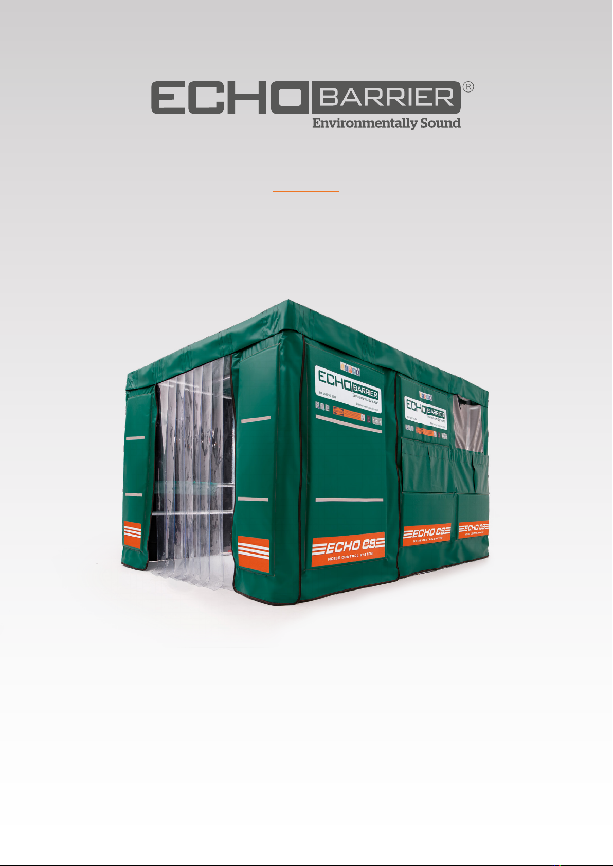
CS Cutting Station™

The Echo Barrier CS Cutting Station™is a temporary portable acoustic
enclosure that can be erected with ease to contain noise from cutting
activities. Its innovative design oers superior noise reduction and absorption
from all directions without compromising the process for cutting panels,
timbers, tiles, tubes or beams of any length. It is ideal for use indoors or
next to high rise structures. The viewing window provides visibility for
communication and safe working. The simple, flexible and eective design
comes with all the components required to prevent noise from bouncing o
ceilings and walls, whilst containing dust, debris and fumes.
CS Cutting Station™
echobarrier.com |info@echobarrier.com
125 250 500
Frequency, f [Hz]
1000 2000 4000
0.0
0.1
0.2
0.3
0.4
0.5
0.6
0.7
0.8
0.9
1.0
1.1
1.2
1.3
1.4
Noise Absorption Coecient, a
S
ABSORPTION
12563 250 500
Frequency, f [Hz]
1000 2000 4000
0
10
Noise Reduction Index [dB]
20
30
40
50
60
Shifted Reference Curve;
ISO 717-1 [100 - 3150Hz]
R
INSULATION
NOISE REDUCTION NOISE ABSORPTION

CS Cutting Station™specifications
Eective installation
What makes our acoustic barriers so eective?
Front outer layer
Extremely durable, waterproof, high quality PVC,
with optimum mass to ensure maximum noise
reduction whilst retaining a professional appearance.
Acoustic absorbent
Lightweight acoustic foam prevents
noise reflecting o the barrier.
Waterproof breathable fabric
Multiple purpose breathable fabric
allows noise to be absorbed while
ensuring no water enters the barrier.
Patent protected, ©2017, Trade mark protected 2017
Acoustic shadowNoise source
Noise
receiver
Noise
receiver
Max Noise Reduction (Lab Tested)* 38.5 dB (in all directions)
Max Noise Absorption (Lab Tested)* 89% (in all directions)
Height 2100 mm (6 ft 11 in)
Width 2400 mm (7 ft 10 in)
Length 3250 mm (10 ft 8 in)
Weight 136 kg (300 lb)
Water resistant test standard* BSEN 60529:1992 IPX6/IPX9
Fire resistant test standard* BS 7837-1996 (barriers), class B1 (windows/roof)
Dust resistant test standard* BSEN 60529-1992
Cold resistant test standard (result)* BSEN 60068/2/1:2007 (-40 degrees)
UV resistant 3 years (USA + Canada), 5 years (rest of the world)
Safety features Night-time reflective strips, hazard icons
Quick install 2 persons in 15 minutes, foldable
Installation kits Not required
Frame components / weights Rear frame x 1 = 7 kg (15 lb), side frame x 2 = 11 kg (24 lb) each, front roof frame x 1 = 4
kg (9 lb), rear roof frame x 1 = 3 kg (6.6 lb), wheels x 6 = 3 kg (6.6 lb)
Acoustic components / weights
PVC roof cover = 10.7kg (23.5 lb), acoustic roof barrier = 5.5 kg (12 lb), acoustic side windowed
double panel x 2 = 12 kg (26.5 lb) each, H3 acoustic panel x 2 = 6 kg (13 lb), each acoustic front
panel with plastic door strips = 17.50kg (38.5 lb), air extractor panel =12kg (26.5 lb)
Window option
Included – Window opening can be configured to suit any width of material by simply folding the panels
Ventilation option Includes integral air extraction hood
Adjustable Yes – Height only
Wheels Yes – lockable
Anti-theft Security cable, data tag
Cleaning Power wash
Identification code part number Unique RFID number per unit
Manufacturer’s warranty 1 year
Colour options On request
* Full independent laboratory results can be obtained on request to info@echobarrier.com
Echo Barrier
CS position

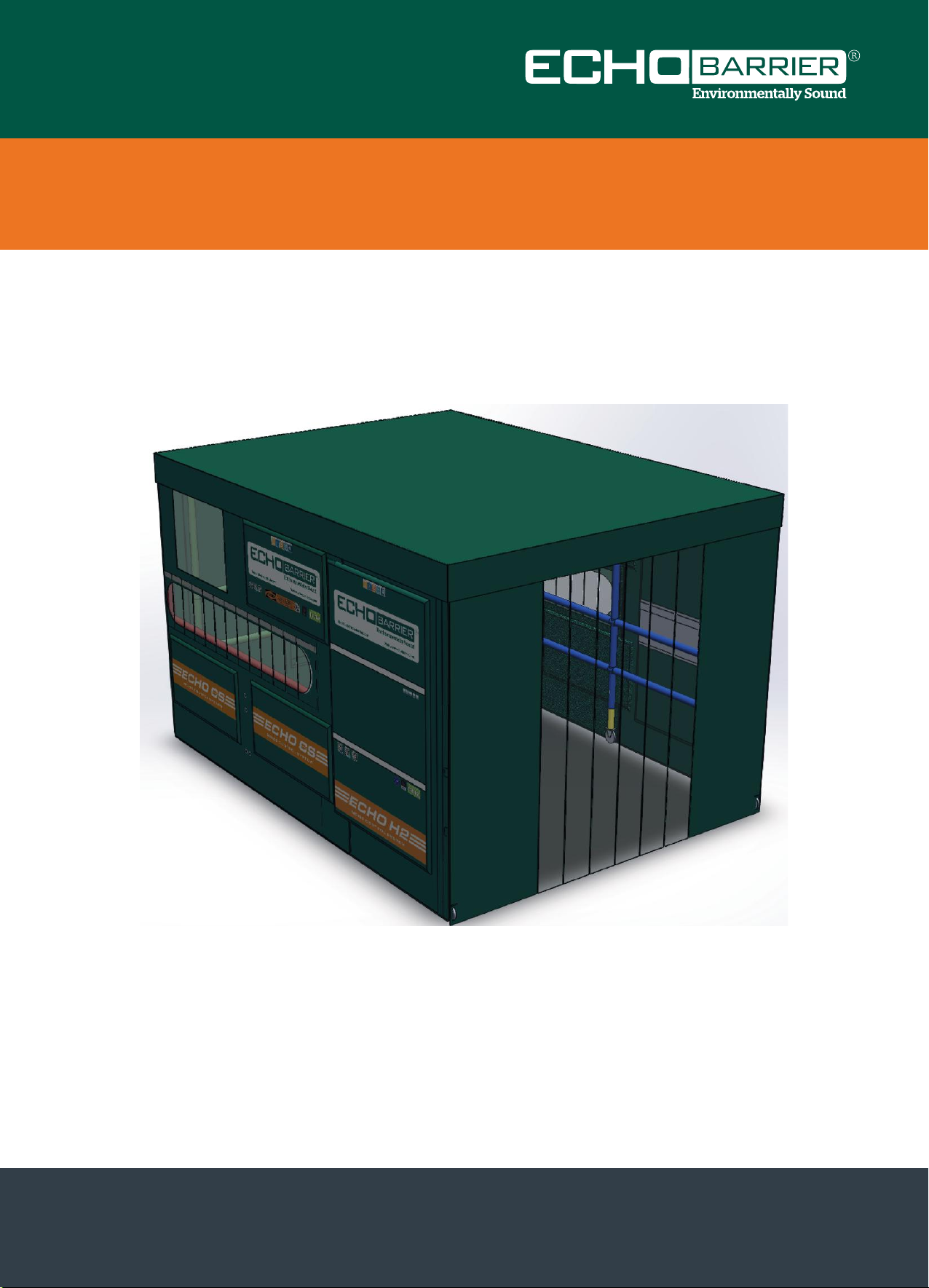
Cutting Station Enclosure - Assembly Instructions
1. Connect RED to GREEN – the RED middle vertical tube is offset from the centre;
ensure the smaller gap is away from GREEN
2. Connect BLUE to GREEN – ensure the smaller gap is away from GREEN.
3. Attach GREY roof brace.
4. Attach YELLOW roof brace.
5. Insert the wheels along one side, then the remaining side.
Note: The frames are not actually coloured.
Tel: 0208 408 7107 info@echobarrier.com www.echobarrier.co.uk
Stage 1 - Frame

Cutting Station Enclosure - Assembly Instructions
Attach the CS barriers. Wrap the Velcro aps around the top tubes and secure in place.
a. Ensure that the viewing window is at the back of the frame.
b. Attach the Velcro on the slots to the frame.
Tel: 0208 408 7107 info@echobarrier.com www.echobarrier.co.uk
Stage 2 - Le and Right hand side barrier placement

Cutting Station Enclosure - Assembly Instructions
Attach the ventilation barrier using the Velcro straps on the top tube.
a. Attach the ventilation hole Velcro straps to the horizontal tubes.
b. Fold the CS barriers around the corner and attach to the ventilation barrier using the
Velcro strips.
Tel: 0208 408 7107 info@echobarrier.com www.echobarrier.co.uk
Stage 3 -Rear barrier placement

Cutting Station Enclosure - Assembly Instructions
Attach the smaller Echo Barriers to the frame. The CS barrier overlap these and attach by Velcro
Tel: 0208 408 7107 info@echobarrier.com www.echobarrier.co.uk
Stage 4 - Left and Right hand side single barrier placement

Cutting Station Enclosure - Assembly Instructions
Attach the door panel. Fold the edges around the corner and attach to the small Echo
Barriers by the Velcro.
Tel: 0208 408 7107 info@echobarrier.com www.echobarrier.co.uk
Stage 5 - Door panel barrier placement

Cutting Station Enclosure - Assembly Instructions
Attach the roof barrier above the ventilation barrier.
a. Make sure the Velcro tabs are lined up the same as the picture below, then
fasten them to the frame.
Tel: 0208 408 7107 info@echobarrier.com www.echobarrier.co.uk
Stage 6 - Roof panel barrier placement
Cutting Station Enclosure - Assembly Instructions
Place the roof over the structure and attach it the barriers all the way around using the Velcro.
Note: Adjust the frame height by turning the wing nuts on the wheels to work with your
cutting bench.
Tel: 0208 408 7107 info@echobarrier.com www.echobarrier.co.uk
Stage 7 - Roof placement
Table of contents
Popular Safety Equipment manuals by other brands

Temperature Guard
Temperature Guard VM605 Manual and installation instructions

PRIMAL TREESTANDS
PRIMAL TREESTANDS PTDH-903W Instruction and safety manual

MSA
MSA M1 Cleaning And Disinfection Guide

mShield
mShield mVISOR7001 user manual

Restube
Restube PFD instruction manual

Henriksen
Henriksen REBS user manual


Honeywell
Honeywell Miller VC300 user guide

MSA
MSA Ultima X Series Safety manual

TEUFELBERGER
TEUFELBERGER OD LOOP 7 MM Manufacturer's information and instructions for use

Cooper Lighting
Cooper Lighting AtLite AUX Series installation instructions

Dräger
Dräger Oxyboks KT Instructions for use

Sweet Protection
Sweet Protection Knee Pads user manual