Echo PB-8010 User manual

Ref. No. 403-21
(Serial number: 38000001 and after)
Copyright(C)2020 YAMABIKO Corporation All rights reserved.
PB-8010
ECHO:
shindaiwa:
EB810
REVISED NOV. 2020

INTRODUCTION
This service manual contains information for
service and maintenance of ECHO BACKPACK
BLOWER model PB-8010 and shindaiwa
BACKPACK BLOWER model EB810.
For systematic diagnosis, to avoid extra work,
time loss and to meet Emission regulation,
please refer to “Troubleshooting guide” that
describes problems, testing, remedies and
references. We recommend you make use of
Operator’s Manual and Parts Catalogue together
with this manual when servicing.
We are constantly working on technical improve-
ment of our products. For this reason, technical
data, equipment and design are subject to
change without notice. All specifications, illustra-
tions and directions in this manual are based on
the latest product information available at the
time of publication.

TABLE OF CONTENTS
PB-8010, EB810 1
Page Page
1 SERVICE INFORMATION.....................................2
1-1 Specifications ...................................................2
1-2 Technical data ..................................................3
1-3 Torque limits .....................................................4
1-4 Special repairing materials...............................4
1-5 Service limits ....................................................5
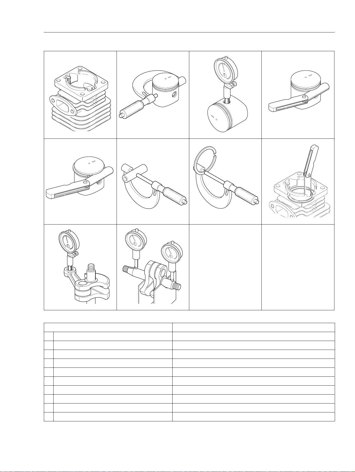
1-6 Special tools.....................................................6
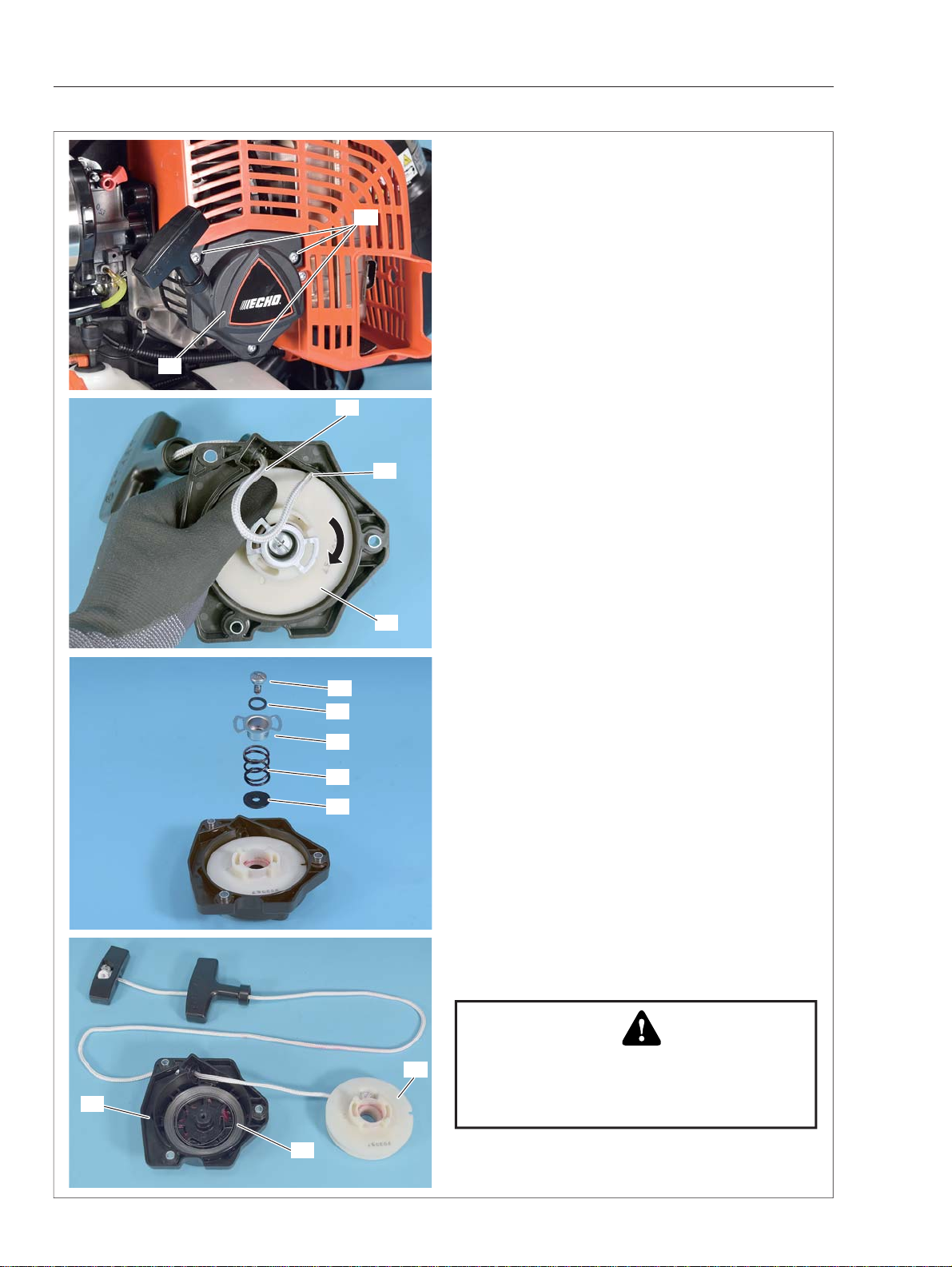
2 STARTER SYSTEM..............................................7
2-1 Disassembling starter assembly.......................8
2-2 Replacing starter rope......................................9
2-3 Installing rewind spring...................................10
2-4 Assembling starter..........................................12
2-5 Replacing starter pawl....................................13
3 IGNITION SYSTEM.............................................14
3-1 Troubleshooting guide....................................15
3-2 Testing spark ..................................................16
3-3 Inspecting spark plug .....................................16
3-4 Replacing spark plug cap and coil..................17
3-5 Inspecting ignition switch................................17
3-6 Replacing ignition switch................................18
3-7 Inspecting ignition coil resistance...................21
3-8 Replacing ignition coil.....................................22
3-9 Setting pole shoe air gaps..............................22
3-10 Inspecting and replacing magneto rotor.........23
3-11 Inspecting and replacing woodruff key...........23
4 FUEL SYSTEM ...................................................24
4-1 Inspecting air filter ..........................................25
4-2 Inspecting fuel cap and fuel strainer...............25
4-3 Inspecting fuel tank and line...........................26
4-4 Replacing fuel lines and grommet..................27
4-5 Inspecting tank vent .......................................28
4-6 Replacing carburetor......................................29
4-7 Testing carburetor...........................................30
4-8 Inspecting crankcase pulse passage .............31
4-9 Inspecting metering lever height ....................31
4-10 Inspecting inlet needle valve ..........................32
4-11 Inspecting diaphragm and others...................33
4-12 Inspecting main jet .........................................33
4-13 Adjusting carburetor .......................................34
4-13-1 General adjusting rules ..............................34
4-13-2 Initial setting Throttle adjust screw,
L mixture needle and H mixture needle..........34
4-13-3 Adjusting carburetor ...................................35
4-14 Checking and adjusting throttle cable ............35
5 BACKPACK FRAME ..........................................36
5-1 Removing backpack frame assembly.............37
5-2 Replacing backpack harness .........................38
5-3 Replacing backpack harness .........................39
6 BLOWER SYSTEM.............................................40
6-1 Separating fan case assembly .......................41
6-2 Replacing elbow.............................................42
6-3 Disassembling and assembling fan................43
6-4 Replacing fan case.........................................43
7 ENGINE...............................................................45
7-1 Testing cylinder compression .........................46
7-2 Cleaning cooling air passages .......................46
7-3 Inspecting muffler and exhaust port ...............47
7-4 Testing crankcase and cylinder sealings........48
7-5 Replacing oil seal ...........................................49
7-6 Inspecting cylinder..........................................50
7-7 Inspecting piston and piston ring....................51
7-8 Disassembling crankcase...............................51
7-9 Replacing ball bearings..................................52
7-10 Removing ball bearing in crankcase ..............52
7-11 Assembling crankshaft and crankcase...........53
7-12 Installing piston...............................................53
7-13 Installing piston ring and cylinder ...................54
7-14 Assembling engine assembly and
other parts ......................................................55
8 MAINTENANCE GUIDE......................................56
8-1 Troubleshooting guide....................................56
8-2 Disassembly chart..........................................58
8-3 Service intervals .............................................59

SERVICE INFORMATION PB-8010, EB810
2
1 SERVICE INFORMATION
1-1 Specifications
Dimensions* Length mm (in) 362 (14.3)
Width mm (in) 526 (20.7)
Height mm (in) 544 (21.4)
Dry weight** kg (lb) 11.2 (24.7)
Engine Type YAMABIKO, stratified scavenging, air-cooled,
two-stroke, single cylinder
Rotation Counterclockwise as viewed from the output end
Displacement cm3 (in3) 79.9 (4.875)
Bore mm (in) 53.0 (2.087)
Stroke mm (in) 36.2 (1.425)
Compression ratio 6.9
Carburetor Type Diaphragm, horizontal-draft, with purge bulb
Model Walbro WYAB-1
Venturi size mm (in) 10.0 x 16.0 (0.39 x 0.63)
Throttle bore mm (in) 16.7 x 16.0 (0.66 x 0.63)
Air valve venturi mm (in) 15 (0.59)
Ignition Type CDI (Capacitor discharge ignition) system
Digital magneto
Spark plug NGK CMR7H
Exhaust Muffler type Spark arrester muffler
Starter Type Automatic rewind
Rope diameter x length mm (in) 3.8 x 1100 (0.15 x 43.3)
Fuel*1Type*2Mixed two-stroke fuel
Mixture ratio 50 : 1 (2%)
Gasoline Minimum 89 octane
Two-stroke air cooled engine oilISO-L-EGD (ISO/CD13738), JASO FC/FD
Tank capacity Full tank capacity: 2.56 (86.6)
L (U.S.fl.oz.) Usable capacity: 2.48 (83.9)
Throttle Type Throttle control and Throttle setting device
Blower Fan type Centrifugal, single stage
Max. air volume (with pipes) m3/min (cfm) 30.3 (1071)
Max. air velocity (with pipes) m/s (mph) 94.5 (211)
Discharge ID*3mm (in) 90.0 (3.5)
*Without blower pipes **With blower pipes
*1Refer to Operator’s manual
*2Premixed alkylate fuel for 2-stroke can be used.
*3Inner diameter

SERVICE INFORMATION
PB-8010, EB810 3
1-2 Technical data
Engine
Compression pressure MPa (kgf/cm2) (psi) 1.03 (10.5) (150)
Ignition system
Spark plug gap mm(in) 0.6 - 0.7 (0.024 - 0.028)
Spark test Tester gap w/ spark plug mm(in) 4.0 (0.16)
Tester gap w/o spark plug mm(in) 6.0 (0.24)
Secondary coil resistance Ω785 - 1185
Pole shoe air gaps mm(in) 0.3 - 0.4 (0.012 - 0.016)
Ignition timing at 3,000 r/min °BTDC 27
at 7,500 r/min °BTDC 30
Carburetor
Test Pressure, minimum MPa (kgf/cm2) (psi) 0.05 (0.5) (7.0)
Metering lever height mm(in) 1.50 (0.06) lower than diaphragm seat
Limiter plug / cap -
Tool to adjust mixture needles Short type D-shaped tool(S) P/N 91159S
Carburetor adjustment
1) Initial setting
H mixture needle turn out 2 1/2
L mixture needle turn out 2
Throttle adjust screw turn out*19 1/4
Engine warm-up Idle - WOT : Total sec. 30 - 180 : 210
2) Find idle maximum speed Adjust L mixture needle to maximum idle speed
3) Set idle maximum speed w/ TAS r/min 2900
4) Set idle speed
by turning L mixture needle CCW r/min 2500
5) Find WOT maximum speed
First, warm-up 180 sec. with WOT engine speed
7650 r/min over and adjust H mixture needle to
maximum WOT speed.
6) WOT setting r/min Turn H mixture needle CCW
to decrease WOT speed by : 60 - 80
7) Verify final engine speed with standard equipment Idle: 2300 - 2700
r/min WOT: 7500 <
BTDC: Before top dead center WOT: Wide open throttle CCW: Counterclockwise TAS: Throttle adjust screw
*1Turn TAS clockwise until its head touches boss. Then turn TAS counterclockwise.

SERVICE INFORMATION PB-8010, EB810
4
1-3 Torque limits
Descriptions Size kgf•cm N•m in•lbf
Starter system Starter case** M5*45 - 65 4.5 - 6.5 40 - 55
Ignition system Magneto rotor (Flywheel) M10 300 - 400 30 - 40 260 - 348
Ignition coil M4* 30 - 45 3 - 4.5 25 - 40
Spark plug M10 100 - 150 10 - 15 87 - 130
Fuel system Carburetor M5 40-60 4-6 32-50
Intake insulator M5* 60-80 6-8 50-70
Engine Crankcase M5 60-90 6-9 50-80
Cylinder M5* 70-90 7-9 60-80
Engine mount M6* 140 - 180 14 - 18 120 - 157
with lead M6* 130 - 180 13 - 18 110 - 157
Engine Fan case side M5†20-40 2-4 17-32
cover Crankcase side** M5*45 - 65 4.5 - 6.5 40 - 55
Muffler M6 100 - 140 10 - 14 87 - 120
Others Fancase M5†25 - 45 2.5 - 4.5 22 - 40
Blower fan M10 300 - 340 30 - 34 260 - 280
Fuel tank M5* 20-40 2-4 17-32
Cleaner case M5†25-40 2.5-4 22-32
Cylinder cover M4 15 - 45 1.5 - 4.5 13 - 40
Back pack Fan case side M5†25 - 45 2.5 - 4.5 22 - 40
frame Bottom side M5†35-60 3.5-6 30-50
Regular bolt, nut and screw M3 6-10 0.6-1 5-9
M4 15 - 25 1.5 - 2.5 13 - 22
M5 25 - 45 2.5 - 4.5 22 - 40
M6 45 - 75 4.5 - 7.5 40 - 65
M8 110 - 150 11 - 15 95 - 130
* Precoat bolt: If the coat is peeled off, replace new one or apply thread locking sealant as shown below.
†Tapping screw
** Bolts on PB-8010 were changed. Refer to Technical Information Y2020-695 for details.
1-4 Special repairing materials
Material Location Remarks
Grease Oil seal inner lips
EPNOC AP2 (Lithium based grease)
P/N X695-000060
Rewind spring
Starter center post
Main pipe O-ring
Thread locking sealant Ignition coil (re-use*)
ThreeBond #1344J or equivalent
Engine mount (re-use*)
Cylinder (re-use*)
Loctite #272 or equivalent
Intake insulator (re-use*)
ThreeBond #1324N or equivalent
Fuel tank (re-use*)
Starter case (re-use*)
Crankcase side engine cover (re-use*)
*If old thread locking sealant is left in threads, correct torque may not be secured. In case old thread locking
sealant is left, remove it.

SERVICE INFORMATION
PB-8010, EB810 5
5K228 5K229 5K230
5K231 5K016 5K042
012345678910 11 12
0510
5K171 5K232
5K244
5K243
5K219
1-5 Service limits
ABCD
EFGH
KL
Description mm (in)
A Cylinder bore When plating is worn and aluminum can be seen
B Piston outer diameter Min. 52.88 (2.082)
C Piston pin bore Max. 13.030 (0.5130)
D Piston ring groove Max. 1.3 (0.051)
E Piston ring side clearance Max. 0.15 (0.006)
F Piston pin outer diameter Min. 12.98 (0.5110)
G Piston ring width Min. 1.15 (0.045)
H Piston ring end gap Max. 0.5 (0.02)
K Con-rod small end bore Max. 16.025 (0.6309)
L Crankshaft runout Max. 0.02 (0.000 8)

SERVICE INFORMATION PB-8010, EB810
6
Ignition Air Gap Gauge
#.014 = .35mm
P/N 91004
1.35
0.4
1.65
1.5
Made in Germany
T27x200
4 0 1 0 5 5 7 8 6 9 7 4 5
1-6 Special tools
Key Part Number Description Reference
1 X602-000340 Torx wrench (T27) Removing and installing torx bolt
2 897802-33330 Tachometer PET-1000R Measuring engine speed to adjust carburetor
3 897800-79931 Spark tester Checking ignition system
4 91004 Module air gap gauge Adjusting pole shoe air gaps
5 Y089-000111 Puller Removing magneto rotor (flywheel) and crankcase
6 91159S Short type D-shaped tool(S) Adjusting carburetor
7 91087 Fan remover Removing blower fan
8 897563-19830 Metering lever gauge Measuring metering lever height on carburetor
9 91041 Pressure rubber plug Plugging exhaust port to test crankcase / cylinder leakages
10 897826-16131 Pressure rubber plug Plugging intake port to test crankcase / cylinder leakages
11 897827-16131 Pressure plate Plugging intake port to test crankcase / cylinder leakages
12 A131-000160 Pressure connector Testing crankcase and cylinder leakage
13 91149 Pressure / vacuum tester Testing crankcase / cylinder leakages
14 897803-30133 Pressure tester Testing carburetor and crankcase leakage
15 91037 Compression gauge Measuring cylinder compression
16 P021-051690 Adapter Measuring cylinder compression (with P/N: 91147)
17 897701-14732 Bearing tool Removing and installing ball bearings on crankcase
18 897701-02830 Bearing wedge Removing ball bearings on cankshaft
19 100014-18430 Washer Installing crankcase oil seal (t: 0.5 mm)
20 897714-24330 Oil seal tool Installing crankcase oil seal (starter side)
21 897726-21430 Oil seal tool Installing crankcase oil seal (fancase side)
22 897702-30131 Piston pin tool Removing and installing piston pin
23 897719-02830 Piston holder Making piston steady to remove and install piston/ring
12345
6891213
14 15 16 17 18
19
11
10
20 21 22 23
7

STARTER SYSTEM
PB-8010, EB810 7
2 STARTER SYSTEM
(A) Starter case
(B) Collar
(C) Rewind spring
(D) Rope reel
(E) Washer
(F) Spring
(G) Shutter
(H) Thrust washer
(J) Starter rope
(K) Rope guide
(L) Starter grip
(M) Grip cap
(N) Pawl (2 pcs)
(A)
(B)
(C)
(D)
(E)
(F)
(G)
(H)
(J)
(L)
(M)
(K)
(N)

STARTER SYSTEM PB-8010, EB810
8
2-1 Disassembling starter assembly
1. Remove 3 bolts (A) and remove starter assem-
bly (B) from unit.
2. Pull out starter rope (C) about 30 cm (12 in) and
hold rope reel (D) by hand. Hook excess rope on
rope reel notch (d1) as shown.
3. Rotate rope reel (D) clockwise to release ten-
sion of rewind spring.
4. Remove screw (E), thrust washer (F), shutter (G),
spring (H) and washer (J) from starter assembly.
5. Remove rope reel (D) from starter case (K)
slowly to prevent rewind spring (M) from unwind-
ing.
d1
C
D
E
F
G
H
J
WARNING DANGER
Wear eye protection and take care when
removing rope reel. Rewind spring may un-
wind suddenly and cause personal injury.
D
M
K
A
B

STARTER SYSTEM
PB-8010, EB810 9
2-2 Replacing starter rope
1. Pull out knot (c1) from starter grip and untie knot
(c1).
2. Pull knot (c2) to remove rope from rope reel.
3. When installing a new starter rope, singe both
ends of the rope to prevent fraying.
4. Make a knot (c2) at end of starter rope and pass
the rope through hole of rope reel, then push the
knot (c2) into recess as shown.
5. Pass the other end of starter rope (C) through
starter case (K) from inside to outside.
6. Pass starter rope (C) through starter grip (N)
and grip cap (P). Make a knot (c1) as shown.
7. Push the knot (c1) into recess of grip cap (P).
c1
c2
c2
c2
c1
c1
K
C
N
P
P

STARTER SYSTEM PB-8010, EB810
10
2-3 Installing rewind spring
If rewind spring is popped out unexpectedly, follow
steps 1) to 13) to install it into original position.
1) Due to large spring load, it is recommended to
use the following tool.
2) This tool can be made by assembling suitable
board (Q), bolt or bar (R; < 13 mm dia.) and bolt
or bar (S; < 3 mm dia.) as follows.
3) Set inner hook (m1) of rewind spring on rib (d2)
of rope reel as shown.
4) Turn over rope reel (D) with rewind spring (M)
and install the tool for winding spring as shown.
NOTE: Set rewind spring (M) inside the small bolt
or bar (S) as shown.
5) Turn rope reel (D) with rewind spring (M) coun-
terclockwise to wind the spring.
WARNING DANGER
Wear eye protection and take care when
removing rope reel. Rewind spring may un-
wind suddenly and cause personal injury.
< 33 mm
< 13 mm dia.
< 3 mm dia.
< 4 mm
R
S
Q
R
S
Q
m1
d2
D
M
S
M

STARTER SYSTEM
PB-8010, EB810 11
2-3 Installing rewind spring (Continued)
6) Continue to turn rope reel (D) counterclock-
wise until the outer hook (m2) of rewind spring is
caught on the small bolt or bar (S) as shown.
7) While holding rope reel firmly to keep rewind
spring winded, bind outside of winded rewind
spring with strong string, such as cable tie (T)
firmly not to unwind the spring.
8) Remove rope reel and rewind spring (M) gen-
tly.
9) Cut off the rest (t1) of cable tie.
10) Apply small amount of lithium based grease
to outside of rewind spring (M) and shaft of starter
case (K).
11) Align outer hook (m2) of spring with holder (k1)
of starter case.
12) Push rewind spring (M) down into the bot-
tom of case, keeping the spring strongly pressed
against case.
13) Spring (M) should fall into starter case and
cable tie (T) can be removed.
NOTE: Rewind spring supplied as spare part is shipped in temporary retainer. Install the spring and re-
move the retainer as above step 11) to 13).
m2
D
t1
T
lithium based
grease
K
M
k1 m2
m2
T
K
M

STARTER SYSTEM PB-8010, EB810
12
2-4 Assembling starter
1. Install rope reel (D) engaging rib (d2) with inner
hook (m1) of rewind spring.
NOTE: Check for proper engagement of rewind
spring and rope reel (D) by turning rope reel (D)
clockwise and counterclockwise.
2. Insert collar (U) between shaft of starter case
and rope reel (D).
3. Apply small amount of lithium based grease to
spring (H).
4. Install washer (J), spring (H), shutter (G) and
thrust washer (F) to starter.
5. Apply thread locking sealant (Loctite #263 or
equivalent) to bolt (E) and tighten the bolt (E).
6. Pull out starter rope (C) inside of starter case.
Rotate rope reel (D) counterclockwise several
turns with starter rope hooked at notch (d1) as
shown. Hold rope reel (D) to prevent it from un-
winding and pull out starter grip to take the rope
slack.
7. Pull starter several times to check rewind spring
tension. If starter is not rewinding fully, increase
spring tension by rotating rope reel (D) one more
turn counterclockwise following above step 6.
8. Pull out starter rope all the way, and check that
rope reel (D) can be rotated an additional half or
more turn counterclockwise as shown, to prevent
rewind spring from breaking.
9. If rope reel (D) can not be turned counterclock-
wise, reduce tension by rotating rope reel (D)
clockwise one turn with starter rope hooked at
notch (d1).
d2
m1
D
E
F
G
H
J
D
D
U
lithium based
grease
Loctite#263
d1
C
D

STARTER SYSTEM
PB-8010, EB810 13
2-5 Replacing starter pawl
1. Remove magneto roter (Refer to “3-10 Inspect-
ing and replacing magneto rotor”).
2. Remove E-ring (V) from pawl (N).
3. Inspect spring (W) and pawl (N) for damage.
Replace the part(s) as required.
4. Install spring (W) to pawl (N) as shown.
5. Install spring (W) and pawl (N) to magneto roter
as shown.
6. Install new E-ring (V) to pawl (N).
V
N
N
W
WN
V
N

IGNITION SYSTEM PB-8010, EB810
14
3 IGNITION SYSTEM
(A) Magneto rotor (Flywheel) (F) Spark plug cap coil
(B) Woodruff key (G) Spark plug cap
(C) Ignition coil (H) Primary wires
(D) High tension lead (J) Ground wires
(E) Spark plug (K) Ignition switch
(B)
(A)
(C)
(D)
(E)
(F)
(G)
(K)
(H)
(H)
(J)
(J)

IGNITION SYSTEM
PB-8010, EB810 15
3-1 Troubleshooting guide
Not
OK
Not
OK
Not
OK
OK
OK
OK
Spark plug
Spark
plug cap/
coil
Ignition
switch
Clean /
Regap /
Replace.
Replace.
Start
OK
OK
S.T.
Not
OK
S.T.
Not
OK
Not
OK
S.T.
OK
S.T.
Not
OK Pole
shoe air
gaps
Replace.
Not
OK OK
Not
OK
S.T.
OK
OK
Replace
ignition
coil.
Leads
connections
Not
OK
OK
OK
Not
OK
S.T.
Repair /
Replace.
Not
OK
Remedy
Inspect
Not
OK
Flywheel
key
OK
R.T.*
End
Not
OK
Flywheel
magneto
Replace.
Not
OK
R.T.
Not
OK
OK
OK
Replace ignition coil and / or inspect other
systems.
Replace flywheel.
OK
OK
Adjust pole shoe air gaps.
(Inspect flywheel magnet
at the same time. Go to
Aif OK.)
S.T.
Not
OK
A
S.T.: Spark test.
R.T.: Running test including actual cutting.
OK
OK
Secondary
coil
resist-
ances

IGNITION SYSTEM PB-8010, EB810
16
3-2 Testing spark
WARNING DANGER
*Do not test near spark plug hole without
spark plug installed, otherwise there is a
chance to ignite fuel mixture inside cylinder.
*Do not touch metal parts of spark tester
while performing the test to avoid receiving
electrical shock.
*Do not check spark in area where gasoline
is spilled or flammable gases may exist.
Using Spark tester 897800-79931 (A)
1. Pull off spark plug cap (B).
2. Push high tension terminal (a1) onto spark plug
cap (B). Connect ground terminal (a2) to spark
plug (C).
3. Screw in adjuster (a3) until the needle tips
contact. Turn out the adjuster 4 turns to set spark
tester gap (a4) to 4 mm (0.16 in).
4. Pull the starter grip several times.
5. If spark is steady blue or white at the tester gap,
ignition system is considered good. Go to inspect-
ing spark plug.
6. If no spark exists or spark is intermittent in
yellow, orange, or red, continue with further inspec-
tion.
3-3 Inspecting spark plug
1. Remove spark plug to inspect for spark plug gap
fouling, cracked or broken insulator, cracked outer
electrode, or rounded center electrode. Replace
spark plug as required.
Spark plug gap (A) standard:
0.6 to 0.7 mm (0.024 to 0.028 in)
2. If engine does not start with correct spark plug,
inspect if spark plug is wet or dry. If it is exces-
sively wet or dry, inspect fuel system.
GASO
LINE
A
C
B
a3
a4
a1
a2
A

IGNITION SYSTEM
PB-8010, EB810 17
3-5 Inspecting ignition switch
1. Loosen bolt (A).
2. Disconnect primary wire (B) and ground wire (C).
3. Connect Ohm-meter or Multi-meter to primary
wire (B) and ground wire (C) as shown.
4. When ignition switch is in “RUN” position, the
tester should indicate infinite resistance.
5. When ignition switch is in “STOP” position, the
tester should show that circuit is in conducting
state (closed circuit).
6. If not, replace the ignition switch with new one
(Go to “3-6 Replacing igntion switch”).
3-4 Inspecting and Replacing spark plug cap and coil
1. Pull off spark plug cap (A).
2. Apply some oil in the spark plug cap (A) for easy
removal from high tension lead (B).
3. Pull spark plug cap (A) away from high tension
lead (B).
4. Inspect spark plug cap coil (C) for corrosion
and correct connection. Inspect spark plug cap for
cracks. Replace them as required.
NOTE: Make sure spark plug cap coil (C) contacts
center core of high tension lead.
5. Coat end of high tension lead (B) with small
amount of oil, and insert the high tension lead (B)
into spark plug cap (A) as shown, until the spark
plug cap coil (C) is properly seated in the cap.
A
B
A
B
A
B
C
Coat with oil
C

IGNITION SYSTEM PB-8010, EB810
18
3-6 Replacing ignition switch
If ignition switch is damaged, the entire control
cable assembly (G) must be replaced.
Removing
1. Disconnect primary wire (A) and ground wire (B)
(Refer to 3-5 Inspecting ignition switch).
2. Disconnect throttle cable end (c1) from carbure-
tor.
3. Remove four screws (D).
4. Remove handle grip half (E).
5. Disconnect throttle cable end (c2) from throttle
trigger (F).
6. Pull control cable assembly (G) with cable con-
nector (H) and bolt (J) out from the handle grip.
7. Pull control cable assembly (G) out from the
cable connector (H).
Ac1
Control cable assembly
D
E
c2
c2
F
H
G
J
G
H
B
G
Other manuals for PB-8010
1
This manual suits for next models
1
Table of contents
Other Echo Blower manuals

Echo
Echo PB-265LN User manual

Echo
Echo PB-760LNH User manual

Echo
Echo PB-46LN User manual

Echo
Echo PB-251E - PARTS CATALOG SN P09012001001 - P09012999999 REV... Instruction Manual

Echo
Echo PB-251E - PARTS CATALOG SN P06113001001-P06113999999 REV... Instruction Manual

Echo
Echo PB-460LN User manual

Echo
Echo SHRED 'N' VAC ES-252 User manual

Echo
Echo PB-252 LA User manual

Echo
Echo MB-580 User manual

Echo
Echo ES-255ES User manual