Echo PB-620 User manual

2
Copyright© 2006 By Echo, Incorporated
All Rights Reserved.
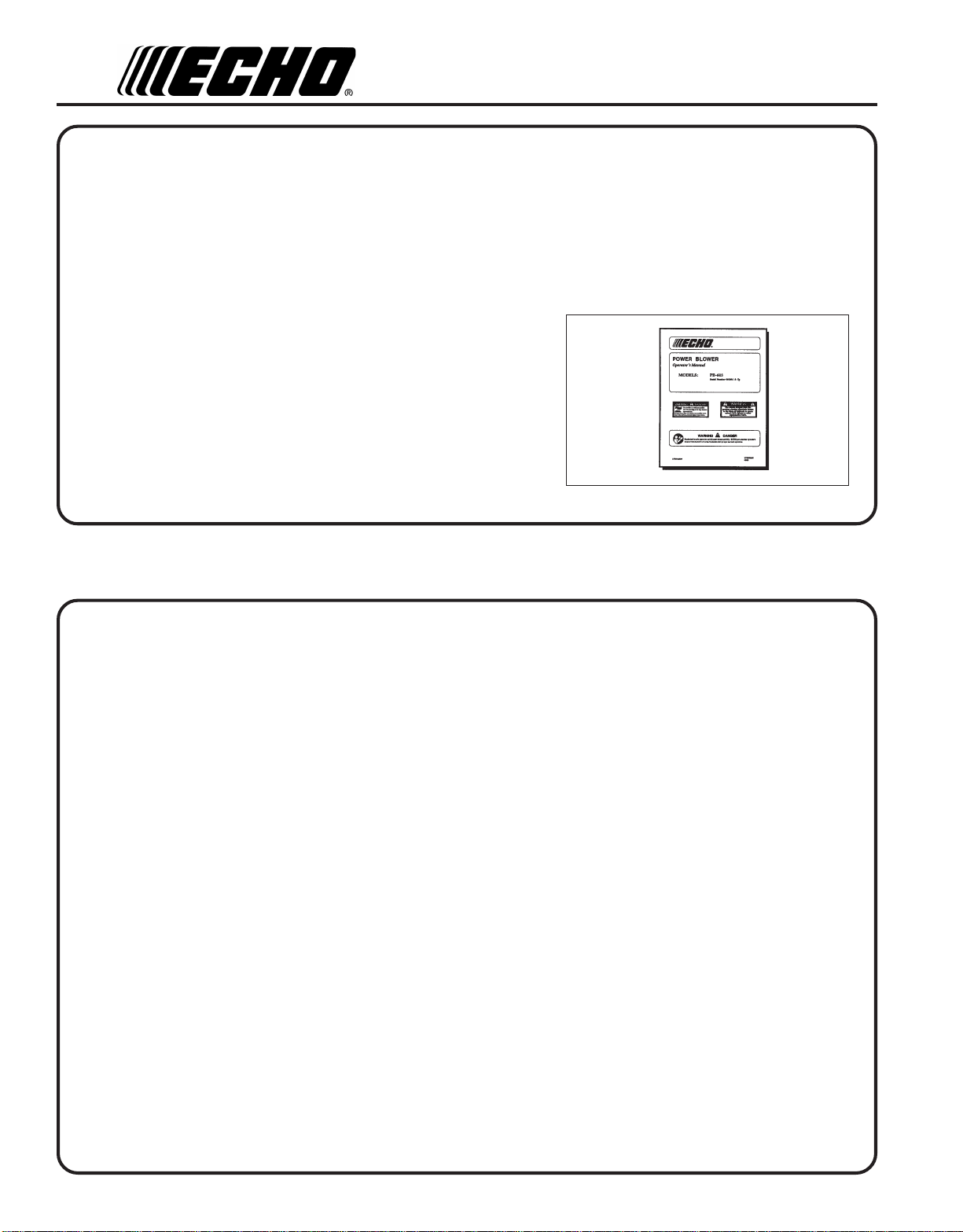
THE OPERATOR'SMANUAL
Read and understand this manual before operation. Keep it in a safe
place for future reference. It contains specifications and information for
operation, starting, stopping, maintenance, storage, and assembly
specific to this product.
TABLE OF CONTENTS
Introduction ................................................................... 2
- The Operator's Manual ........................................... 2
Safety ............................................................................. 3
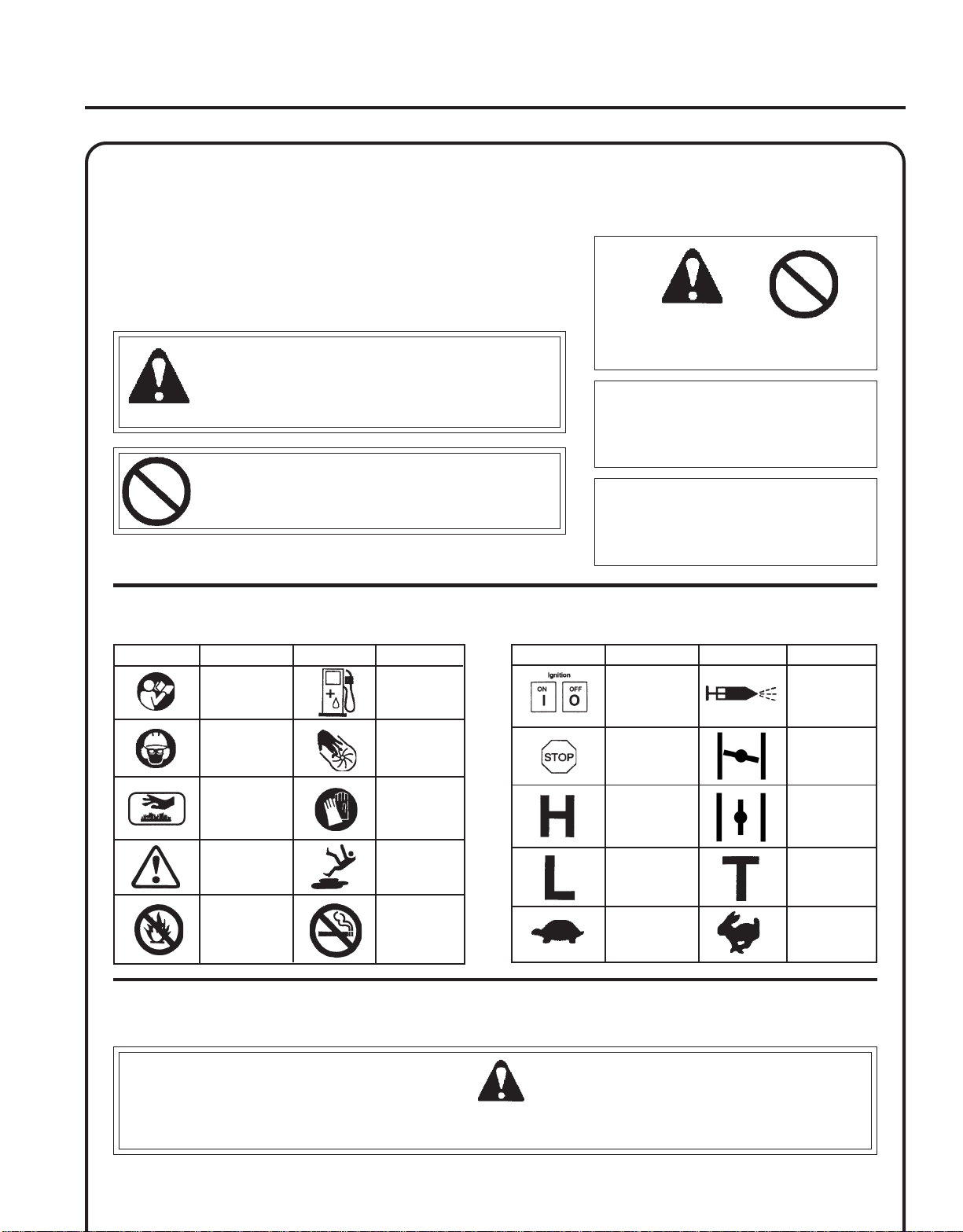
- Manual Safety Symbols and Important Information 3
- InternationalSymbols ............................................. 3
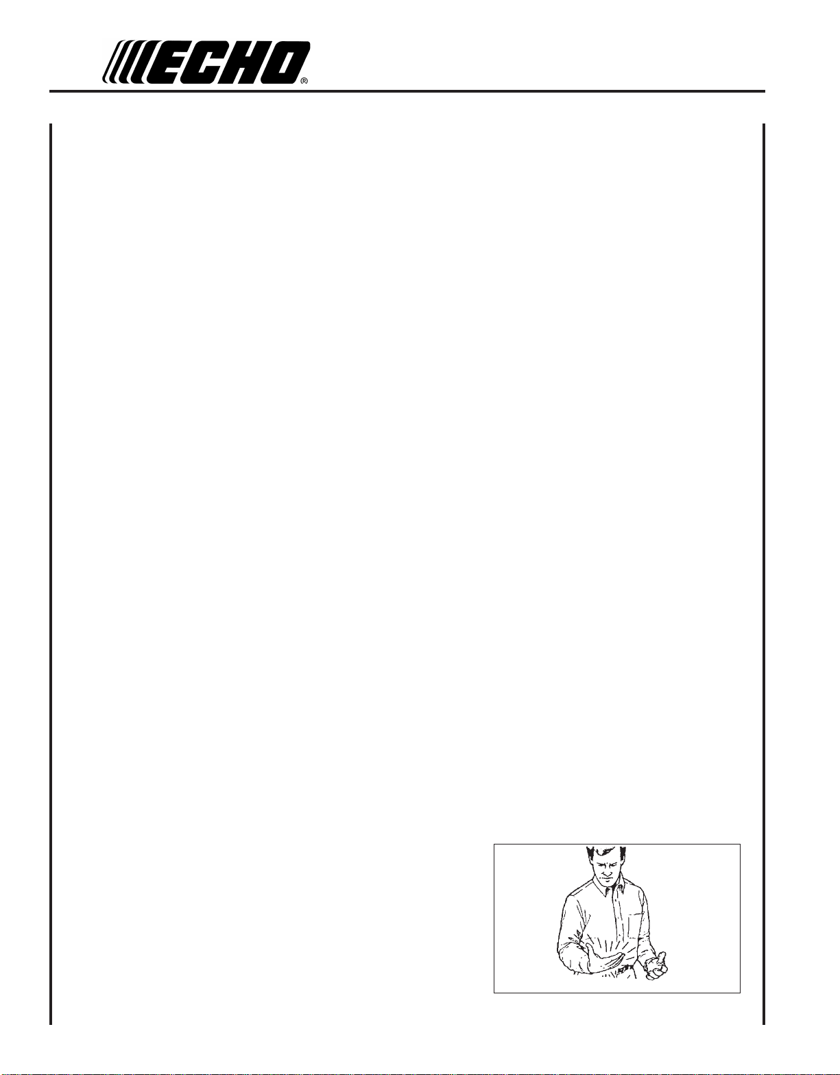
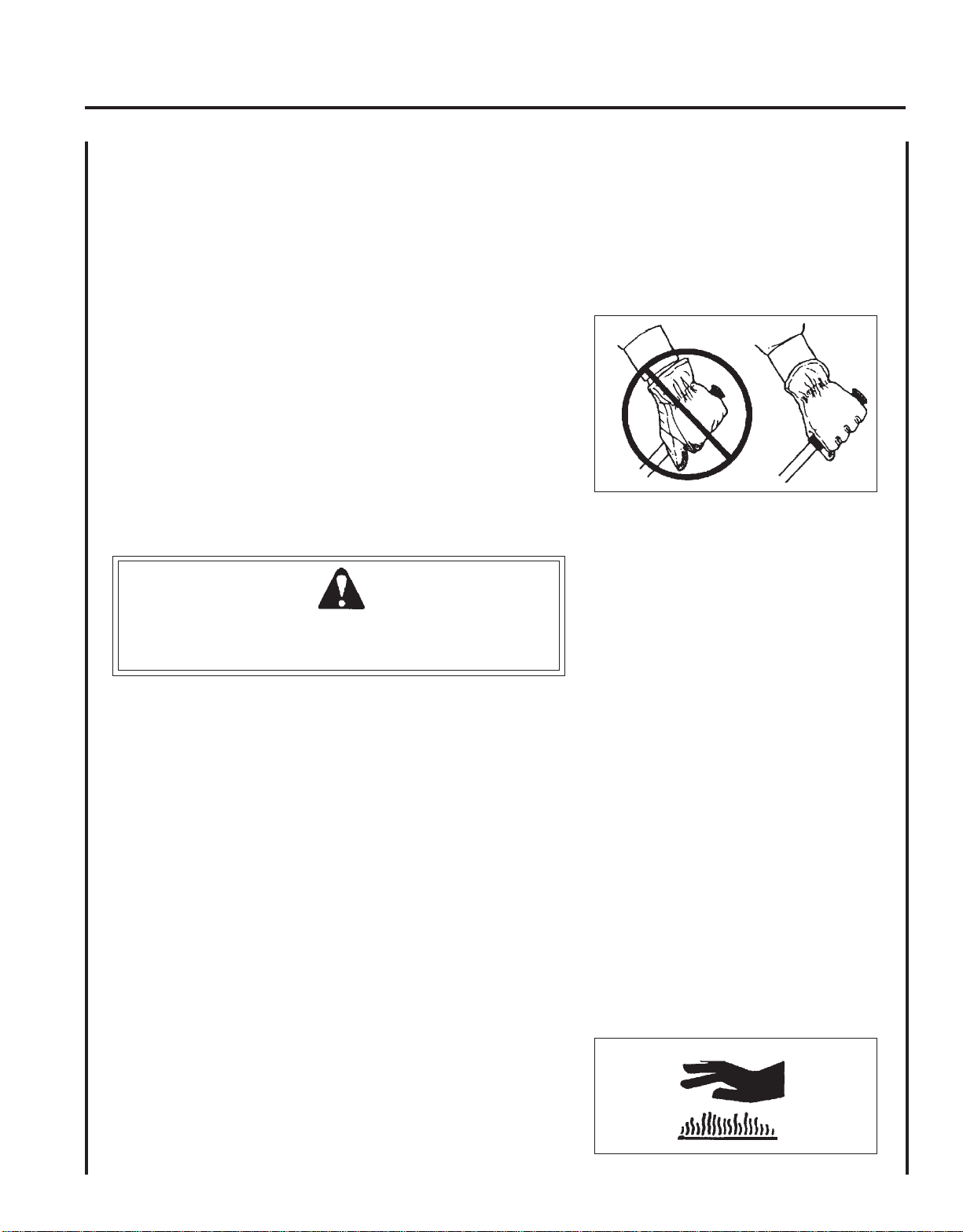
- Personal Condition and Safety Equipment ............. 3
- EquipmentCheck .................................................... 6
EmissionControl............................................................ 6
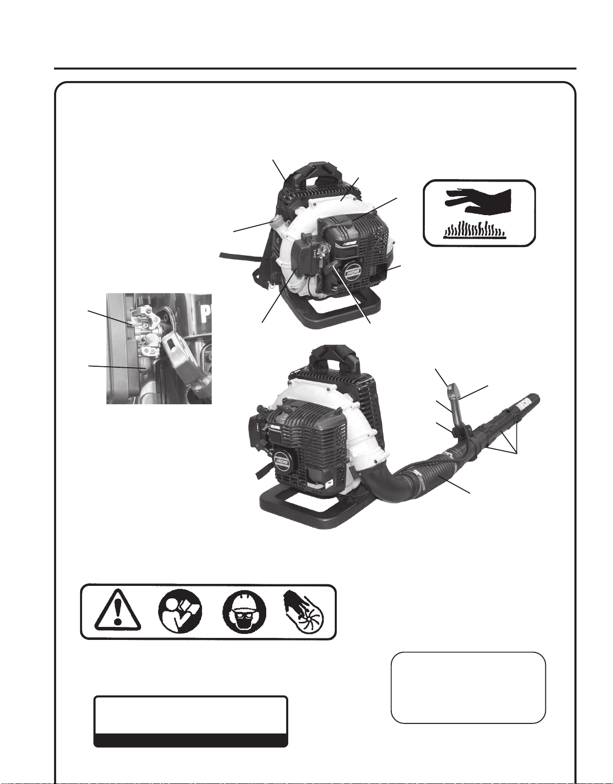
Description .................................................................... 7
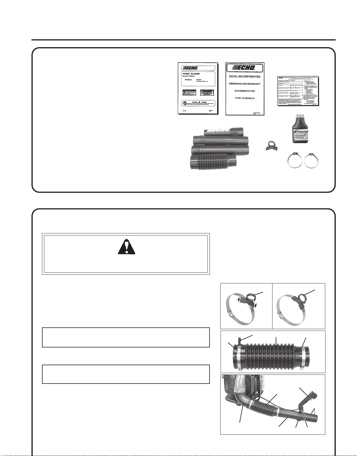
Contents ........................................................................ 9
Assembly ....................................................................... 9
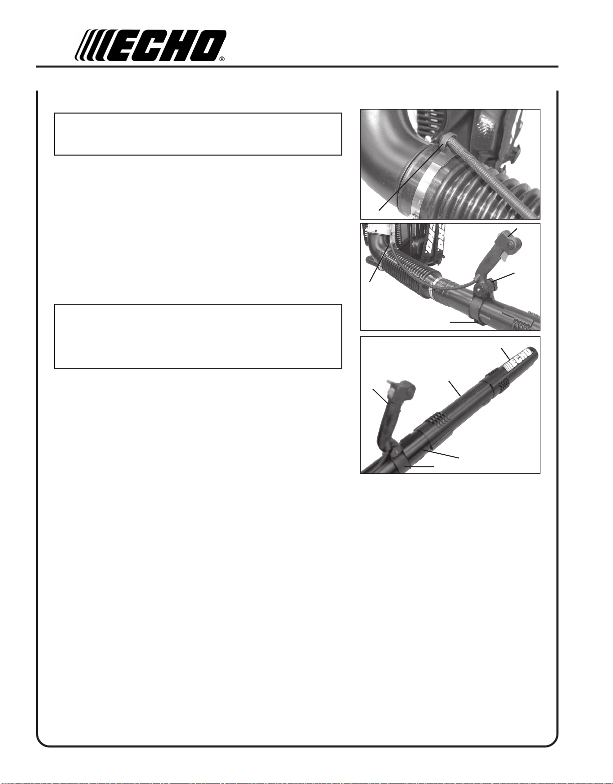
- InstallBlowerPipes ................................................ 9
Operation ..................................................................... 11
- Fuel ....................................................................... 11
- StartingColdEngine ............................................. 12
- StartingWarmEngine ........................................... 12
- Stopping Engine ................................................... 13
- OperatingBlower .................................................. 13
Maintenance ................................................................ 14
- SkillLevels ............................................................ 14
- Maintenance Intervals .......................................... 15
- AirFilter................................................................ 16
- FuelFilter .............................................................. 16
- SparkPlug ............................................................. 17
- CoolingSystem..................................................... 17
- ExhaustSystem..................................................... 18
- Carburetor Adjustment ......................................... 19
Troubleshooting .......................................................... 21
Storage......................................................................... 22
Specifications............................................................... 23
ServicingInformation................................................... 24
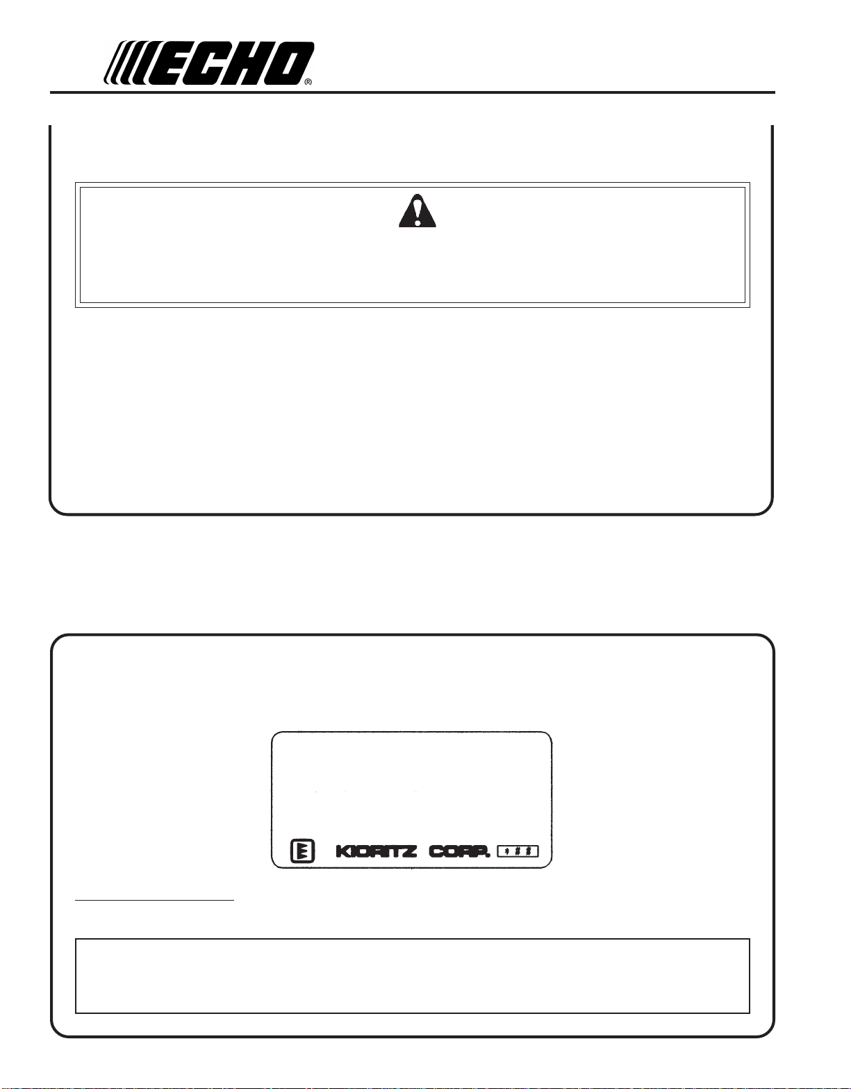
- Parts/SerialNumber ...................................................... 24
- Service .................................................................. 24
- ECHOConsumerProductSupport........................ 24
- Warranty Registration .......................................... 24
- Additional or Replacement Manuals .................... 24
Specifications, descriptions and illustrative material in this
literature are as accurate as known at the time of publica-
tion, but are subject to change without notice. Illustrations
may include optional equipment and accessories, and may
not include all standard equipment.
INTRODUCTION
Welcome to the ECHO family. This ECHO product was designed and manufactured to provide long life and on-the-job
dependability. Read and understand this manual. You will find it easy to use and full of helpful operating tips and
SAFETYmessages.

3
POWER BLOWER
OPERATOR'SMANUAL
IMPORTANT
The enclosed message provides
information necessary for the protection
of the unit.
NOTE
This enclosed message provides tips
for use, care and maintenance of the
unit.
SAFETY
MANUAL SAFETY SYMBOLS AND IMPORTANT INFORMATION
IMPORTANT
NOTE
Throughout this manual and on the product itself, you will find safety
alerts and helpful, informational messages preceded by symbols or key
words. The following is an explanation of those symbols and key
words and what they mean to you.
This symbol accompanied by the words WARNING and
DANGER calls attention to an act or condition that can lead
to serious personal injury to operator and bystanders.
The circle with the slash symbol means whatever is shown
within the circle is prohibited.
INTERNATIONAL SYMBOLS
PERSONAL CONDITION AND SAFETY EQUIPMENT
WARNING DANGER
Power Blower users risk injury to themselves and others if the power blower is used improperly or safety precautions
are not followed. Proper clothing and safety gear must be worn when operating a blower.
SYMBOL
Carburetor
Adjustment
-Idlespeed
Carburetor
Adjustment
-Highspeed
mixture
Stop
Carburetor
adjustment
-Lowspeed
mixture
Ignition
ON/OFF Purge
Bulb
Choke Control
"Cold Start"
Position
(ChokeClosed)
Choke Control
"Run"
Position
(ChokeOpen)
DESCRIPTION SYMBOL DESCRIPTION
Hot
Surface
Read and under-
stand Operator's
Manual.
Weareyes,ears
andhead
protection
Fueland oil
mixture
Finger
Severing
Safety/Alert
Wear hand
protection.Use
twohanded.
DONOTsmoke
nearfuel.
DONOTallow
flamesorsparks
nearfuel.
Wear slip
resistantfoot
wear.
SYMBOL DESCRIPTION SYMBOL DESCRIPTION
IdleSpeed FastSpeed

4
Physical Condition
Your judgment and physical dexterity may not be good:
• if you are tired or sick,
• if you are taking medication,
• if you have taken alcohol or drugs.
Operate unit only if you are physically and mentally well.
Eye Protection
Wear eye protection that meets ANSI Z87.1 or CE requirements whenever you operate the unit.
Hand Protection
Wear no-slip, heavy-duty work gloves to improve your grip on the blower handle. Gloves also reduce the transmission
of machine vibration to your hands.
Breathing Protection
Wear a facemask to protect against dust.
Hearing Protection
ECHO recommends wearing hearing protection whenever unit is used.
Proper Clothing
Wear snug fitting, durable clothing;
• Pants should have long legs, shirts with long sleeves.
• DONOTWEARSHORTS,
• DONOTWEARTIES,SCARVES,andJEWELRY.
Wear sturdy work shoes with nonskid soles:
• DONOTWEAROPENTOEDSHOES,
• DONOTOPERATEUNITBAREFOOTED.
Keep long hair away from engine and blower intake. Retain hair with cap or net.
Hot Humid Weather
Heavy protective clothing can increase operator fatigue, which may lead to heat stroke. Schedule heavy work for early
morning or late afternoon hours when temperatures are cooler.
Vibration and Cold
It is believed that a condition called Raynaud’s Phenomenon, which affects the fingers of certain individuals, may be
brought about by exposure to vibration and cold. Exposure to vibration and cold may cause tingling and burning
sensations, followed by loss of color and numbness in the fingers. The following precautions are strongly recom-
mended,because the minimum exposure, whichmight trigger theailment, is unknown.
• Keep your body warm, especially the head, neck, feet, ankles,
hands, and wrists.
• Maintain good blood circulation by performing vigorous arm
exercises during frequent work breaks, and also by not smoking.
• Limit the hours of operation. Try to fill each day with jobs where
operating the unit or other hand-held power equipment is not
required.
• If you experience discomfort, redness, and swelling of the fingers
followed by whitening and loss of feeling, consult your physi-
cian before further exposing yourself to cold and vibration.

5
POWER BLOWER
OPERATOR'SMANUAL
WARNING DANGER
Do not operate this product indoors or in inadequately ventilated
areas. Engine exhaust contains poisonous emissions and can cause
serious injury or death.
Read the Manuals
• Provide all users of this equipment with the Operator’s Manual
and Safety Manual for instructions on Safe Operation.
Clear the Work Area
• Spectators and fellow workers must be warned, and children and
animalspreventedfromcomingnearerthan15m(50ft.)while the
unit is in use.
• Take wind conditions into account: avoid open doors and
windows.
• Do not point blower at people or animals.
Keep a Firm Grip
• Hold the front and rear handles with both hands, with thumbs
and fingers encircling the handles.
Keep a Solid Stance
• Maintain footing and balance at all times. Do not stand on
slippery, uneven or unstable surfaces. Do not work in odd
positions or on ladders. Do not over reach.
Avoid Hot Surfaces
• Keep exhaust area clear of flammable debris. Avoid contact
duringandimmediately afteroperation.
Repetitive Stress Injuries
It is believed that overusing the muscles and tendons of the fingers, hands, arms, and shoulders may cause soreness,
swelling, numbness, weakness, and extreme pain in those areas. Certain repetitive hand activities may put you at a high
riskfordeveloping a Repetitive StressInjury(RSI).An extreme RSI conditionisCarpal Tunnel Syndrome (CTS),which
could occur when your wrist swells and squeezes a vital nerve that runs through the area.
Some believe that prolonged exposure to vibration may contribute to CTS. CTS can cause severe pain for months or
even years.
To reduce the risk of RSI/CTS, do the following:
• Avoid using your wrist in a bent, extended, or twisted position.
Instead try to maintain a straight wrist position. Also, when
grasping, use your whole hand, not just the thumb and index
finger.
• Take periodic breaks to minimize repetition and rest your hands.
• Reduce the speed and force with which you do the repetitive
movement.
• Do exercises to strengthen the hand and arm muscles.
• Immediately stop using all power equipment and consult a
doctor if you feel tingling, numbness, or pain in the fingers,
hands, wrists, or arms. The sooner RSI/CTS is diagnosed, the
more likely permanent nerve and muscle damage can be pre-
vented.

6
EQUIPMENT CHECK
WARNING DANGER
Use only ECHO approved attachments. Serious injury may result from the use of a non-approved attachment
combination. ECHO, INC. will not be responsible for the failure of cutting devices, attachments or accessories which
have not been tested and approved by ECHO. Read and comply with all safety instructions listed in this manual and
safety manual.
• Check unit for loose/missing nuts, bolts and screws. Tighten
and/or replace as needed.
• Inspect fuel lines, tank and area around carburetor for fuel leaks. DO NOT operate unit if leaks are found.
• Do not use blower if any part is missing or damaged.
• Have repairs done only by an authorized ECHO Service dealer.
• Do not use any attachment, accessory or replacement part unless it is recommended in this Operator's Manual.
PRODUCT EMISSION DURABILITY
The 300 hour emission durability compliance period is the time span selected by the manufacturer certifying the
engine emissions output meets applicable emissions regulations, provided that approved maintenance procedures are
followed as listed in the Maintenance Section of this manual.
EMISSIONCONTROL
EPA Phase 2 / California
The emission control system for these engines is EM/TWC (Engine Modification and Catalyst).
AnEmissionControlLabelis located on the unit. (This is an EXAMPLE ONLY,informationonlabelvariesbyengine
FAMILY).
IMPORTANTENGINEINFORMATION
ENGINE FAMILY: 6EHXS.0585KA DISPLACEMENT: 58.2 cc
EMISSIONCOMPLIANCEPERIOD:300HOURS
THIS ENGINE MEETS U.S. EPA PH2 AND 2005 - 2006
CALIFORNIA EMISSION REGULATIONS FOR SOREs.
REFER TO OWNER'S MANUAL FOR MAINTENANCE
SPECIFICATIONS AND ADJUSTMENTS.

7
POWER BLOWER
OPERATOR'SMANUAL
Locate the safety decals on your unit. Make sure the decals are legible and that you understand and follow the instruc-
tions on them. If a decal cannot be read, a new one can be ordered from your ECHO dealer. See PARTS ORDERING
instructionsfor specific information.
DESCRIPTION
1
2
3
4
5
6
7
10
15
11
12
13
14
8
9
Hot Decal (near muffler)
P/N 89016006361
P/N 89016009461
General Warning Decal (located on top of blower housing)
Return to Idle
P/NX505000950
RETURN TO IDLE
BEFORE
SHUTTING OFF
Sound Label (located on blower housing)
72 Category III
dB(A)
Measured at 50 ft. (15m) per ANSI B175.2
P/NX508000150

8
1. SAFETYDECAL-Listsimportantsafetyprecautions.
2. SPARKPLUG-Providessparktoignitefuelmixture.
3. SPARKARRESTOR-CATALYTICMUFFLER/MUFFLER-Themufflerorcatalyticmufflercontrolsexhaustnoise
and emission. The spark arrestor screen prevents hot, glowing particles of carbon from leaving the muffler. Keep
exhaustareaclearofflammabledebris.
4. RECOILSTARTERHANDLE-Pullrecoilhandleslowlyuntilstarterengages,thenquicklyandfirmly. Whenengine
starts, return handle slowly. DO NOT let handle snap back, or damage to unit will occur.
5. AIRCLEANER-Containsreplaceableairfilterelement.
6. FUELTANKCAP-Coversandsealsfueltank.
7. SHOULDER HARNESS - Used to support unit on operator's back. The straps are adjustable.
8. CHOKE - Choke is located on the side of the air cleaner. Move choke lever to "COLD START" ( ) to close choke
for cold starting. Move choke lever to "RUN" ( ) position to open choke.
9. PURGEBULB- Pumping purge bulbbefore starting engine draws freshfuel from the fuel tank,purging air from the
carburetor. Pump purge bulb until fuel is visible and flows freely in the clear fuel tank return line. Pump bulb an
additional4or5times.
10. LOCKINGKNOB-Allowsoperator to adjust handle position for optimumcomfortandcontrol.
11. HANDLE-Used byoperatorto direct andcontrol air flow.
12. COMBINATIONTHROTTLEPOSITION/STOPSWITCHBUTTON-Controlsenginespeedandturnsignitionon
or off. Forward position - STOP. First detent position - IDLE. Move button back to increase speed, forward to
decrease speed. Use Throttle Position Button to set and hold blower speed for continuous operation.
13. THROTTLETRIGGER-Spring-loadedThrottleTriggercontrolsenginespeed. ReleasingTriggerreturnsengineto
speed setting set by Throttle Position Stop Switch Button. Always release trigger and allow engine to return to idle
before shutting off with Throttle Position Stop Switch Button. Use Throttle Trigger to vary blower speed settings for
intermittentoperation.
14. BLOWERPIPES-Exclusivepositivelockingsystem.
15. FLEXIBLEPIPE-Allowsforfullrangeofmovement.

9
POWER BLOWER
OPERATOR'SMANUAL
ASSEMBLY
WARNING DANGER
Never perform maintenance or assembly procedures with engine
running or serious personal injury may result.
INSTALL BLOWER PIPES
1. Place guide loop (H) across elbow clamp, and turn until clips fully
engage clamp band.
2. Assemble clamps (A) onto both ends of flexible pipe (B).
NOTE
Clampwithcableguideloop(H)fitselbow end of flexible pipe.
3. Assembleswivelpipe(C)intoflexiblepipe(B).
NOTE
Assure throttle cable is not twisted before installing handle (F).
4. Position cable between the elbow (D) and frame and along the top
ofthe flexiblepipe.Removeclampscrew(E) onhandle(F).Align
notch in handle with tabs (G). Spread clamp and install onto swivel
pipe (C) past long ridges in pipe.
5. Assemble flexible pipe (B) to elbow (D) on blower and tighten
clamps(A).
CONTENTS
___ 1- PowerHead
___ 1 - FlexPipe
___ 1- Pipew/swivel
___ 1- StraightPipe
___ 1- StraightPipew/decal
___ 1 - Operator's Manual
___ 1 - Warranty Registration Card
___ 1- ECHOEmissions and Warranty Statement
___ 1- PlasticBag
___ 2- Clamps w/screws
___ 1-GuideLoop
___ 1- EchoPower Blend TM 2-stroke oil sample
H
AA
B
HH
F
B
I
G
DE
C

10
NOTE
A light lubricant may be used to ease assembly of flexible pipe to
blowerelbow.
6. Clip throttle cable into guide loop (H).
7. Move handle (F) to desired position. Tighten knob (I) hand tight.
Installand tightenclamp screw (E).
8. Assemble straight pipe (J) onto swivel pipe (C), until you feel light
resistance. Do not force connection. Hold swivel pipe and turn
straight pipe clockwise, engaging positive locking channels, until
connection is firm. Do not force connection.
9. Assemble straight pipe with decal (K) to straight pipe (J) as in step
8.
NOTE
Blower use will eventually loosen pipe connections. Exclusive
positive locking system allows pipes to be tightened. If loosening
occurs, remove two straight pipes and install according to instruc-
tions 8 & 9.
F
E
J
K
C
H
F
I
E
H

11
POWER BLOWER
OPERATOR'SMANUAL
oitaR1:05-xiMliOotleuF
.S.UCIRTEM
SAGLIOSAGLIO
snollaG.zo.lFretiL.cc
1
2
5
6.2 2.531
4
8
02
08 061 004
Mixing Instructions
1. Fill an approved fuel container with half of
the required amount of gasoline.
2. Add the proper amount of 2-stroke oil to
gasoline.
3. Close container and shake to mix oil with
gasoline.
4. Add remaining gasoline, close fuel
container,andremix.
IMPORTANT
Spilled fuel is a leading cause of
hydrocarbon emissions. Some states
may require the use of automatic fuel
shut-off containers to reduce fuel
spillage.
After use
• DO NOT store a unit with fuel in its
tank. Leaks can occur. Return unused
fuel to an approved fuel storage
container.
Storage - Fuel storage laws vary by locality.
Contact your local government for the laws
affecting your area. As a precaution, store
fuel in an approved, airtight container. Store
in a well-ventilated, unoccupied building,
away from sparks and flames.
IMPORTANT
Storedfuelages. Do not mixmorefuel
than you expect to use in thirty (30)
days, ninety (90) days when a fuel
stabilizeris added.
IMPORTANT
Stored two-stroke fuel may separate.
ALWAYS shake fuel container thor-
oughly before each use.
OPERATION
NOTICE:Useofunmixed,improperlymixed,orfuelolderthan90
days, (stale fuel), may cause hard starting, poor performance, or
severe engine damage and void the product warranty. Read and
follow instructions in the Storage section of this manual.
FUEL
Fuel Requirements
Gasoline- Use89 Octane [R+M/2] (mid gradeor higher) gasoline known
to be good quality. Gasoline may contain up to 15% MTBE (methyl
tertiary-butylether). Gasoholcontaining methyl (wood) alcohol isNOT
approved.
TwoStrokeOil-Atwo-strokeengineoilmeetingISO-L-EGD(ISO/CD
13738)and J.A.S.O.FC Standards must be used. Echobrand premium
Power Blend TM Universal 2-Stroke Oil meets these standards. Engine
problems due to inadequate lubrication caused by failure to use an ISO-
L-EGDandJ.A.S.O.FCcertifiedoil,suchasEchopremiumPowerBlend
TM, will void the two-stroke engine warranty. (Emission related parts
only are covered for two years, regardless of two-stroke oil used, per the
statement listed in the Emission Defect Warranty Explanation.)
IMPORTANT
EchopremiumPowerBlendTM Universal2-StrokeOilmaybemixedat
50:1 ratio for application in all Echo engines sold in the past regard-
less of ratio specified in those manuals.
Handling Fuel
WARNING DANGER
FuelisVERYflammable.Useextremecarewhenmixing,storingor
handling or serious personal injury may result.
• Use an approved fuel container.
• DONOTsmokenearfuel.
• DONOTallowflamesorsparksnearfuel.
• Fuel tanks/cans may be under pressure. Always loosen fuel
caps slowly allowing pressure to equalize.
• NEVERrefuelaunitwhentheengineisHOTorRUNNING!
• DONOTfillfueltanksindoors.ALWAYSfillfueltanksout-
doors over bare ground.
•DONOToverfillfueltank. Wipeupspillsimmediately.
• Securely tighten fuel tank cap and close fuel container after
refueling.
• Inspect for fuel leakage. If fuel leakage is found, do not start or
operate unit until leakage is repaired.
• Move at least 3m (10 ft.) from refueling location before starting
the engine.

12
STARTING COLD ENGINE
• Recoil starter: Use short pulls - only 1/2-2/3 of rope length for
starting. Do not allow the rope to snap back in. Always hold the unit
firmly.
1. Throttle Position/Stop Switch Button
Slide Throttle Position /Stop Switch Button (A) back to idle position
(first detent away from stop position)
2. Choke
Move choke (B) up to Cold Start position ( ).
3. Purge Bulb
Pump purge bulb (C) until fuel is visible and flows freely in the clear
fuel tank return line. Pump bulb an additional 4 or 5 times.
4. Recoil Starter
Pullrecoilstarterhandle(D)untilenginefires(5 pullsmaximum).
5. Choke
Move choke (B) down to run position ( ), and if necessary,
restart engine.
NOTE
If engine does not start after 5 pulls, move choke to "Cold Start"
position, and repeat steps 4 & 5.
NOTE
Allow engine to warm up before use.
A
D
B
C
STARTING WARM ENGINE
The starting procedure is the same as Cold Start except DO NOT close
the choke.
1. Throttle Position/Stop Switch Button
Slide Throttle Position /Stop Switch Button (A) back to idle position
(first detent away from stop position)
A

13
POWER BLOWER
OPERATOR'SMANUAL
2. Purge Bulb
Pump purge bulb (C) until fuel is visible and flows freely in the clear
fuel tank return line. Pump bulb an additional 4 or 5 times.
3. Recoil Starter
Pull recoil starter handle (D) and engine should start.
NOTE
If engine does not start after 5 pulls, use cold start procedures. D
C
STOPPING ENGINE
1. Throttle Position/Stop Switch Button
Release throttle trigger. Move Throttle Position /Stop Switch Button
(A) forward to idle position (first detent away from stop position)
and allow engine to return to idle before shutting off engine.
2. Throttle Position/Stop Switch Button
Move Throttle Position /Stop Switch Button (A) all the way forward
to STOP position.
WARNING DANGER
If engine does not stop when stop switch is moved to STOP
position, close choke - COLD START position - to stall engine.
Have your ECHO dealer repair stop switch before using blower
again.
OPERATING BLOWER
WARNING DANGER
Always wear safety glasses, hearing protection, a face filter mask,
and take all safety precautions, or serious personal injury may
result.
Do not point the blower pipe in the direction of people or pets.
Read the Safety Section carefully.
IMPORTANT
To avoid engine damage due to over-revving, do not block blower
pipe opening.
A

14
A
B
1. Use only during appropriate hours.
2. Allow the engine to warm up at a fast idle for a few minutes.
3. Control blower speed with Throttle Trigger (B), or for continuous
use, set engine speed with Combination Throttle Position /Stop
SwitchButton (A).
4. Use lower speed to blow dry leaves from walks, patios and drives.
5. Additional speed may be necessary to clean grass and leaves from a
lawnor flower bed.
6. Higher speed may be necessary to move gravel, dirt, snow, bottles
or cans from a driveway, street, parking lot or stadium.
7. Always stop unit using stop engine procedure.
NOTE
Never use a higher speed setting than necessary to perform a task.
Remember, the higher the engine speed, the louder the blower noise.
Minimize dust by using blower at lower speeds and by dampening
material with water/mist when necessary. Keep debris on your
property.
Be Smart - be a good neighbor.
MAINTENANCE
Your ECHO blower is designed to provide many hours of trouble-free service. Regular scheduled maintenance will help
your blower achieve that goal. If you are unsure or are not equipped with the necessary tools, you may want to take your
unit to an ECHO Service Dealer for maintenance. To help you decide whether you want to DO-IT-YOURSELF or have the
ECHO Dealer do it, each maintenance task has been graded. If a task is not listed, see your ECHO Dealer for repairs.
SKILL LEVELS
Level1= Easy to do. Most required tools come with unit.
Level2= Moderate difficulty. Some specializedtools may be required.
Level3= Experience required. Specialized tools are required. Echo recommends the unit be returned to your Echo
Dealerforservicing.
ECHO offers REPOWERTM Maintenance Kits and Parts to make your maintenance job easier. The various part numbers
required for each task are listed below the task heading. See your ECHO dealer for these parts.

15
POWER BLOWER
OPERATOR'SMANUAL
MAINTENANCE INTERVALS
/TNENOPMOC METSYS ECNANETNIAM ERUDECORP
D'QER LLIKS LEVEL
YLIAD RO EROFEB ESU
YREVE LEUFER
3SHTNOM 09RO SRUOH
6SHTNOM 072RO SRUOH
YLRAEY
serudecorPecnanetniaMrelaeDohcEdednemmoceR
troPtsuahxErednilyCnobraceD/naelC/tcepsnI 3C/I
serudecorPecnan
etniaMflesruoY-tI-oD
retliFriAecalpeR/naelC/tcepsnI 1C/I*R
ekohCnaelC/tcepsnI 2C/I
retliFleuFecalpeR/tcepsnI 1I*
R
skaeL,metsySleuFecalpeR/tcepsnI 1I*R/I
metsySgnilooCnaelC/tcepsnI 2C/I
rotserrAkrapSrelffuMecalpeR/tcepsnI 2*
R/I
epoRretratSlioceRnaelC/tcepsnI 1C/I*R/I
gulPkrapSnaelC/tcepsnI 2C/I*R
stloB/stuN/swercSecalpeR/nethgiT/tcep
snI 1*R/I
SEDOCRETTELERUDECORPECNANETNIAM NAELC=C,ECALPER=R,TCEPSNI=I:
-ETONTNATROPMI deriuqerfoycneuqerfehtenimretedlliwecneirepxeruoydnaesulaut
cA.mumixameranwohsslavretniemiT
.ecnanetniam :SETONERUDECORPECNANETNIAM
*.noitcepsnignirudraewroegamadfognidnifehtnodesaberaecalperotsnoitadnemmocerllA

16
AIR FILTER
Level1.
Tools required: 25 -50mm(1-2in.)Cleaningbrush.
Parts required: REPOWERTMTuneUpKitP/N90072
NOTE
Cleandaily.
1. Close choke (Cold Start Position [ ]). This prevents dirt from
entering the carburetor throat when the air filter is removed. Brush
accumulateddirtfromaircleanerarea.
2. Removeairfiltercover.Brushdirt frominsidecover.
3. Removeairfilterandlightlybrushdebrisfromfilter.Replacefilterif
it is damaged, fuel soaked, very dirty, or the rubber sealing edges
aredeformed.
4. If filter can be reused, be certain it:
• Fits tightly in the air filter cavity.
• Is installed with the original side out.
5. Installairfiltercover.
FUEL FILTER
Level1.
Tools required: 200-250mm(8-10in.)lengthofwirewithoneend
bent into a hook, clean rag, funnel, and an approved
fuelcontainer.
Parts required: REPOWERTMTuneUpKitP/N90072
WARNING DANGER
FuelisVERYflammable.Useextremecarewhenmixing,storingor
handling.
1. Use a clean rag to remove loose dirt from around fuel cap and
emptyfueltank.
2. Use the “fuel line hook” to pull the fuel line and filter from the
tank.
3. Remove thefilterfrom the lineandinstall the new filter.

17
POWER BLOWER
OPERATOR'SMANUAL
SPARK PLUG
Level1.
Tools required: 19mm Spark Plugdeep socket, feelergauge
Parts Required: REPOWERTMTuneUpKitP/N90072
IMPORTANT
UseonlyNGKBPM-8Ysparkplug(BPMR-8YinCanada)otherwise
severe engine damage may occur.
1. Remove spark plug, and check for fouling, and worn or rounded
center electrode.
2. Clean the plug or replace with a new one. DO NOT sand blast to
clean.Remainingsandwilldamageengine.
3. Adjust spark plug gap by bending outer electrode.
4. Tightensparkplugto150-170kg/cm(130-150in.lb.).
COOLING SYSTEM
Level2.
Tools required: 25 - 50 mm (1 - 2 in.) cleaning brush, cross head
screwdriver
Parts Required: None, if you are careful.
IMPORTANT
To maintain proper engine operating temperatures, cooling air must
pass freely through the cylinder fin area. This flow of air carries
combustion heat away from the engine.
Overheating and engine seizure can occur when:
• Air intakes are blocked, preventing cooling air from reaching the
cylinder.
• Dust and grass build up on the outside of the cylinder. This build
up insulates the engine and prevents the heat from leaving.
Removal of cooling passage blockages or cleaning of cooling fins is
considered “Normal Maintenance.” Any failure attributed to lack of
maintenance is not warranted.
Cleaning Grill
1. Remove accumulateddebrisfromintakegrillbetweenbackpack
frame and blower housing.
0.65 mm
(0.026 in.)

18
EXHAUST SYSTEM
Spark Arrestor Screen
Level2.
Tools required: Cross head screwdriver, soft metal brush
Parts Required: Sparkarrestor screen,Gaskets (3)
IMPORTANT
Carbon deposits in muffler will cause a drop in engine output and
overheating. Spark arrestor screen must be checked periodically.
1. Remove spark plug and engine cover (five screws).
2. Remove spark arrestor cover (A), gaskets (B) and spark arrestor
screen(C)frommuffler.
3. Clean carbon deposits from muffler components.
NOTE
When cleaning carbon deposits, be careful not to damage the
catalyticelementinsidemuffler.
4. Replace screen if it is cracked, plugged, or has holes burned
through.
5. Assemble components in reverse order.
Cleaning Cylinder Fins
1. Disconnect spark plug lead (A), and pull lead out of upper cover
clampandlowercoverclamp.
2. Remove 5 screws and remove engine cover (B).
3. Clean cylinder fins (C) to allow cooling air to pass freely.
A
B
CA
Cylinder Exhaust Port
Level3.
IMPORTANT
The cylinder exhaust port must be inspected and cleaned of excess
carbon every 3 months or 90 hours of operation in order to maintain
this engine within the emissions durability period. ECHO strongly
recommends that you return your unit to your ECHO dealer for this
importantmaintenanceservice.
B
C

19
POWER BLOWER
OPERATOR'SMANUAL
CARBURETORADJUSTMENT
Engine Break-In
New engines must be operated for a minimum duration of two tanks of
fuel before carburetor adjustments can be made. During the break-in
period your engine performance will increase and exhaust emissions will
stabilize. Idle speed can be adjusted as required.
High Altitude Adjustment
High altitude adjustment may be required for proper operation of this
engine.
IMPORTANT
For engine operation above 2,000 feet, turn the high-speed needle
lean (CW) until the engine runs between 7,000 and 8,000 RPM. Then
turn the low-speed needle lean (CW) until the engine does not
hesitate on acceleration.
For engine operation below 2,000 feet, turn the high-speed needle
rich(CCW)untiltheenginerunsbetween7,000and8,000RPM.
Then turn the low-speed needle rich (CCW) until the engine does
not hesitate on acceleration.
DONOTREMOVELIMITERCAPS!
Level2.
Tools required: Screwdriver,tachometer(EchoP/N99051130017)
Parts required: None.
NOTE
Do not adjust carburetor unless necessary. If you have difficulty,
seeyourECHOdealer.
AdjustmentScrews
Idle Speed (A) Control throttle opening at idle.
Low(LO)Speed(B) Controls amount of fuel at low speed and
supplementary fuel for smooth progression from
idle to high speed.
High(HI)Speed(C) Controls amount of fuel at full throttle
BeforeAdjustment
Checkthat:
• Air filter is clean and properly installed.
• Spark arrestor screen and muffler are free of carbon.
• Blowerpipesare installed.
A
C
B

20
Initial Adjustment
1. With engine off, turn HI speed screw (C) counterclockwise to stop.
2. Turn LO speed screw (B) midway between stops.
3. Turn idle screw (A) until tip of screw just touches throttle plate; then
turn three (3) turns clockwise.
Final Adjustment
IMPORTANT
LimitercapspreventexceedingC.A.R.B.andE.P.A.emissionlimits
and over-rich adjustment, but not over lean adjustment, which can
cause engine failure: Do not exceed recommended HI speed engine
R.P.M. during operation, or for long periods during adjustment.
1. Start engine, run at idle for one minute.
2. Complete warm-up by running at full throttle for 5 minutes, operating
choketwice to clearair from carburetorchambers.
3. Run at idle and accelerate to check for smooth transition from idle to
high speed; if engine hesitates, turn LO speed screw (B) counter-
clockwise 1/8th of a turn at a time until acceleration is smooth.
4. Use a tachometer to adjust idle speed to specifications found on
page23.
A
C
B
Other manuals for PB-620
1
Table of contents
Other Echo Blower manuals

Echo
Echo ES-230 Shred N Vac User manual

Echo
Echo PB-4600 User manual

Echo
Echo PB-500 H User manual

Echo
Echo ES-210 - SERIAL NUMBER 07001001-07999999 User manual

Echo
Echo PB-2100 Instruction Manual

Echo
Echo PB-250 User manual

Echo
Echo SHRED'N'VAC ES-255 User manual

Echo
Echo PB-260 User manual

Echo
Echo PB-403 User manual

Echo
Echo PB-200 - 12-05 User manual