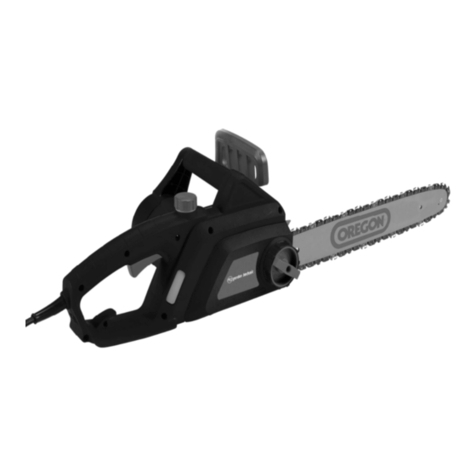
Echo CS-2511WES User manual

Ref. No. 401-44
CS-2511WES
ECHO:
shindaiwa:
251Ws
(Serial number: 38000001 and after)
Copyright C 2019 YAMABIKO Corporation All rights reserved.

INTRODUCTION
This service manual contains information for ser-
vice and maintenance of ECHO CHAIN SAW,
model CS-2511WES and shindaiwa CHAIN
SAW, model 251Ws.
For systematic diagnosis, to avoid extra work,
time loss and to meet Emission regulation,
please refer to “Troubleshooting guide” that
describes problems, testing, remedies and
references. We recommend you make use of
Operator’s Manual and Parts Catalogue together
with this manual when servicing.
We are constantly working on technical improve-
ment of our products. For this reason, technical
data, equipment and design are subject to
change without notice. All specications, illustra-
tions and directions in this manual are based on
the latest product information available at the
time of publication.

TABLE OF CONTENTS
CS-2511WES
251Ws 1
Page Page
1 SERVICE INFORMATION .................................. 2
1-1 Specications ....................................................2
1-2 Technical data ................................................... 3
1-3 Torque limits ...................................................... 5
1-4 Special repairing materials ............................... 5
1-5 Service limits ..................................................... 6
1-6 Special tools ..................................................... 7
2 STARTER SYSTEM (ES-start / S-start) ........... 8
2-1 Disassembling starter assembly .......................9
2-2 Replacing starter rope .................................... 10
2-3 Assembling starter .......................................... 11
2-4 Replacing starter pawl .................................... 13
3 IGNITION SYSTEM ........................................... 14
3-1 Troubleshooting guide .................................... 15
3-2 Testing spark ................................................... 16
3-3 Inspecting spark plug ...................................... 17
3-4 Replacing spark plug cap and coil................... 17
3-5 Inspecting ignition switch ................................ 18
3-6 Replacing ignition switch ................................ 18
3-7 Replacing ignition coil ..................................... 20
3-8 Setting pole shoe air gaps .............................. 21
3-9 Inspecting yweel and key .............................. 21
4 FUEL SYSTEM ................................................. 23
4-1 Inspecting air lter ........................................... 24
4-2 Replacing air cleaner cover latch .................... 25
4-3 Inspecting fuel cap and fuel strainer ............... 25
4-5 Inspecting and replacing tank vent ................. 27
4-6 Replacing purge bulb ...................................... 29
4-7 Replacing fuel line and fuel return line ............ 30
4-8 Adjusting carburetor ........................................ 32
4-8-1 General adjusting rules ................................ 32
4-8-2 Initial setting Throttle adjust screw, L mixture
needle and H mixture needle .......................... 32
4-8-3 Adjusting carburetor ..................................... 33
4-9 Testing carburetor ........................................... 34
4-10 Inspecting crankcase pulse passage ............ 35
4-11 Inspecting metering lever height .................... 35
4-12 Inspecting inlet needle valve ......................... 36
4-13 Inspecting diaphragm and others .................. 37
4-14 Replacing welch plug .................................... 37
4-15 Installing carburetor ....................................... 38
5 CLUTCH SYSTEM ............................................ 39
5-1 Inspecting clutch parts .................................... 39
5-2 Replacing clutch parts .................................... 41
5-3 Installing clutch assembly ............................... 41
6 CHAIN BRAKE SYSTEM .................................. 42
6-1 Replacing brake lever and torsion spring ....... 42
6-2 Inspecting chain brake parts ........................... 44
7 SAW CHAIN LUBRICATION SYSTEM ............. 46
7-1 Inspecting oil cap and strainer ........................ 46
7-2 Inspecting oil tank vent .................................... 47
7-3 Inspecting and replacing oil line ...................... 48
7-4 Inspecting worm gear ..................................... 49
7-5 Cleaning and replacing auto-oiler assembly ... 50
8 ENGINE ............................................................. 53
8-1 Testing cylinder compression .......................... 54
8-2 Cleaning cooling air passages ........................ 55
8-3 Inspecting mufer and exhaust port ................ 56
8-4 Testing crankcase and cylinder sealings ......... 57
8-5 Removing engine block .................................. 58
8-6 Inspecting cylinder .......................................... 59
8-7 Inspecting piston and piston ring .................... 60
8-8 Replacing oil seal ............................................ 61
8-9 Inspecting crankcase and crankshaft ............. 62
8-10 Replacing oil seal and ball bearing................ 63
8-11 Assembling crankshaft and crankcase .......... 64
8-12 Installing piston ring and cylinder .................. 65
9 HANDLE AND CONTROL SYSTEM ................ 66
9-1 Replacing throttle control parts ....................... 67
9-2 Replacing front handle and spring .................. 68
9-3 Replacing rear handle and springs ................. 69
10 GUIDE BAR MOUNTING SYSTEM ................ 71
10-1 Replacing nut for xing guide bar .................. 71
10-2 Replacing chain tensioner ............................. 72
10-3 Replacing guide bar stud............................... 73
11 MAINTENANCE GUIDE ................................... 74
11-1 Troubleshooting guide ................................... 74
11-2 Disassembly chart ......................................... 76
11-3 Service intervals ............................................ 77
SERVICE INFORMATION
2CS-2511WES
251Ws
1 SERVICE INFORMATION
1-1 Specications
Dimensions Length* mm(in) 400 (15.7)
Width mm(in) 213 (8.4)
Height mm(in) 210 (8.3)
Dry weight* kg(lb) 2.6 (5.7)
Engine Type YAMABIKO, air-cooled, two-stroke, single cylinder
Rotation Clockwise as viewed from the output end
Displacement cm3(in3) 25.0 (1.525)
Bore mm(in) 35.0 (1.378)
Stroke mm(in) 26.0 (1.024)
Compression ratio 7.9
Carburetor Type Diaphragm horizontal-draft
Model Walbro WT-1230
Venturi size-Throttle bore mm(in) 11.11 - 14.3 (0.437 - 0.563)
Ignition Type CDI system, Digital magneto
with PI (Proportional integral) Controller
Spark plug NGK CMR7H-10
Exhaust Mufer type Spark arrester mufer with catalyst
Starter Type ES (Effortless-Start) / S (Soft-start)
Rope diameter x length mm(in) 3.0 x 720 (0.12 x 28.3)
Fuel Type** Mixed two-stroke fuel
Mixture ratio 50 : 1 (2 %)
Gasoline Minimum 89 octane petrol
Two-stroke air cooled engine oilISO-L-EGD (ISO/CD13738), JASO FC/FD
Tank capacity L (UK..oz.) 0.19 (6.4)
Clutch Type Centrifugal type, 3-shoe slide with 3-tension spring
Guide bar / Saw chain lubrication type Adjustable automatic oil pump
Oil Tank capacity L (UK..oz.) 0.14 (4.7)
Auto oiler Type Clutch driven type
Sprocket Type Spur
CDI: Capacitor discharge ignition
* Without guide bar and saw chain.
** Premixed alkylate fuel for 2-stroke can be used.

SERVICE INFORMATION 3
CS-2511WES
251Ws
1-1 Specications (continued)
Cutting devices Sprocket nose bar
Guide bar Type C20S91-35SA C25S91-40SL C30S91-47ML
Called length cm 20 25 30
Gauge in 0.050
Saw chain Type Carlton N1C-BL, OREGON 91PX
Number of drive links 35 40 47
Pitch in 3/8
Gauge in 0.050
Sprocket Number of teeth 6
Pitch in 3/8
Cutting devices Carving bar
Guide bar Type C20SA4-52CL C20HA4-52CL C25SA4-60CL C25HA4-60CL
Called length cm 20 25
Gauge in 0.043
Saw chain Type SUGIHARA A4S
Number of drive links 52 60
Pitch in 1/4
Gauge in 0.043
Sprocket Number of teeth 8
Pitch in 1/4
1-2 Technical data
Engine
Compression pressure MPa (kgf/cm2) (psi) 1.03 (10.5) (150)
Clutch engagement speed r/min 4,400
Ignition system
Spark plug gap mm(in) 0.6 - 0.7 (0.024 - 0.028)
Spark test Tester gap w/ spark plug mm(in) 4.0 (0.16)
Tester gap w/o spark plug mm(in) 6.0 (0.24)
Secondary coil resistance Ω960 - 1,000
Pole shoe air gaps mm(in) 0.3 - 0.4 (0.012 - 0.016)
Ignition timing at 1,000 r/min °BTDC 9
at 3,000 r/min °BTDC 9
at 10,000 r/min °BTDC 30
Carburetor
Test Pressure, minimum MPa (kgf/cm2) (psi) 0.05 (0.5) (7.0)
Metering lever height mm(in) 1.65 (0.06) lower than diaphragm seat
Tool to adjust mixture needles D-shaped tool (L) P/N X645-000031
Chain oil discharge volume Adjustable: 1.5 - 13 (0.05 - 0.46)
(Factory set: 6 mL/min)
mL/min (UK..oz./min)
BTDC: Before top dead center

SERVICE INFORMATION
4CS-2511WES
251Ws
1-2 Technical data (continued)
Carburetor adjustment
Fuel type Mixed two-stroke
regular fuel
Mixed two-stroke
E10 fuel
Premixed
alkylate fuel
1) Initial setting H mixture needle turn out 1 3/4 2 2 1/4
L mixture needle turn out 2 1/2
Throttle adjust screw turn in*11 1/2
*1 Set Throttle adjust screw to the point that its tip just contacts throttle plate before initial setting.
IMPORTANT: Use Tachometer PET-1000R to measure engine speed (Refer to 1-6 Special tools).
IMPORTANT: The PI controller installed model has 2 mode; Carburetor adjustment mode and Operation
mode. When adjusting carburetor, must be changed from Operation mode to Carburetor adjustment mode.
The mode will return to the Operation mode when the engine is stopped.
Tochangethemode,
1.Startenginewithoutbrakeactivated.(Do not touch throttle lever.)
2.Enginewarm-upwithfastidlefor120seconds.(The speed should be within 6,000 - 10,000 r/min. If it
is not, adjust the speed by turning H mixture needle.)
CAUTION: Chain will start to rotate during engine warm-up with fast idle.
NOTE: Do not stop engine during carburetor adjustment. If the engine is stopped, restart this procedure from
the beginning.
The carburetor adjustment continues.
Engine warm-up Idle - WOT : Total sec. 5 - 5 : 30
2) Conrm that the mode has changed Conrm to vary the idle engine speed by turning L
mixture needle 1/4 turn CW. If the speed does not
vary, change the mode again.
(Theidleenginespeedreturnsto3,200r/minfora
fewsecondsinOperationmode,whentheengine
speed is deviated.)
3) Find idle maximum speed Adjust L mixture needle to maximum idle speed*2
4) Set idle maximum speed w/ TAS r/min 4,100
5) Set idle speed by turning L mixture needle CCW r/min 3,300
6) Verify nal engine speed with standard equipment Idle: 3,100 - 3,300
WOT: 12,800 - 13,400
r/min
If the WOT speed is not within above range,
readjust H mixture needle and reverify the speed.
If that does not work, adjust H mixture needle by
1/8 turn and reverify the speed.
7) Verify clutch engagement speed Conrm clutch engagement speed.
If it is less than 1.25 times the idle speed,
adjust the idle speed by turning TAS CCW.
WOT: Wide open throttle CCW: Counterclockwise TAS: Throttle adjust screw
*2 If clutch engages during adjustment process 2), decrease engine speed by turning TAS CCW until clutch
disengages and then redo 2).

SERVICE INFORMATION 5
CS-2511WES
251Ws
1-4 Specialrepairingmaterials
Material Location Remarks
Thread locking sealant Stud bolt Loctite #242, ThreeBond #1324 or equivalent
Ignition coil Loctite #222, ThreeBond #1342 or equivalent
Ignition switch Loctite #242, ThreeBond #1324 or equivalent
Grease Recoil starter
EPNOC AP2 (Lithium based grease)
P/N X695-000060
Needle bearing, clutch
Worm gear
Oil seal lip
Chain brake (metal contact part) Molybdenum grease (approx.1 gram)
1-3 Torquelimits
Descriptions Size kgf•cm N•m in•lbf
Starter system Starter pawl M5 30 -45 3 -4.5 25 -40
Starter case M4 20 -30 2 -3 20 -25
Ignition system Magneto rotor (Flywheel) M8 250 -290 25 -29 220 -255
Ignition coil M4* 30 -45 3 -4.5 25 -40
Ignition switch M3* 3 -5 0.3 -0.5 3 -4
Spark plug M10 100 -150 10 -15 90 -135
Fuel system Carburetor M5 30 -45 3 -4.5 26 -40
Intake bellows M4 30 -45 3 -4.5 26 -40
Clutch Clutch hub LM8 250 -290 25 -29 220 -255
Engine Crankcase M4 30 -45 3 -4.5 26 -40
Cylinder M4 30 -45 3 -4.5 26 -40
Engine mount M4 35 -50 3.5 -5 30 -45
Muffler M5 60 -90 6 -9 52 -80
Muffler cover M4†20 -30 2 -3 20 -25
Others Auto-oiler M4 30 -45 3 -4.5 26 -40
Front handle Clutch side M5 30 -40 3 -4 26 -35
Recoil side M4†25 -30 2.5 -3 18 -26
Compression spring M4†20 -35 2 -3.5 20 -30
Brake cover M4†20 -30 2 -3 20 -25
Sprocket guard plate
(Sprocket guard side) M4†20 -30 2 -3 20 -25
Brake lever (Hand guard) M5 30 -45 3 -4.5 26 -40
Chain catcher M5 30 -45 3 -4.5 26 -40
Stud bolt M8*150 -200 15 -20 130 -220
Bolt (at guide bar mount) M5 30 -45 3 -4.5 26 -40
Guide bar nut M8 120 -150 12 -15 105 -135
Spike M5†30 -45 3 -4.5 26 -40
Regular bolt, nut and screw M3 6 -10 0.6 -1 5 -9
M4 15 -25 1.5 -2.5 13 -22
M5 25 -45 2.5 -4.5 22 -40
LM: Left-hand thread * Apply thread locking sealant. (See below)
† Tapping screw

SERVICE INFORMATION
6CS-2511WES
251Ws
1-5 Servicelimits
ABCD
F G H
K L M P
N
E
Description mm (in)
A Cylinder bore When plating is worn and aluminium can be seen
BPiston outer diameter Min. 34. 92 (1.375)
CPiston pin bore Max. 8. 035 (0.3163)
DPiston ring groove Max. 1. 3 (0.051)
EPiston ring side clearance Max. 0. 1 (0.004)
FPiston pin outer diameter Min. 7. 98 (0.3142)
GPiston ring width Min. 1. 15 (0.045)
HPiston ring end gap Max. 0. 5 (0.02)
KCon-rod small end bore Max. 11. 03 (0.4341)
LCrankshaft runout Max. 0. 02 (0.001)
MSprocket bore Max. 13. 07 (0.5146)
NClutch drum bore Max. 53. 5 (2.11)
PSprocket wear limit Max. 0. 5 (0.02)

SERVICE INFORMATION 7
CS-2511WES
251Ws
Key Part Number Description Reference
1 897802-33330 Tachometer PET-1000R Measuring engine speed to adjust Carburetor
2 Y089-000095 Carburetor Adjustment tool Adjusting Carburetor
3X602-000330 Torx wrench (T25) Removing and installing Torx bolt
4X602-000340 Torx wrench (T27) Removing and installing Torx bolt
5 897800-79931 Spark tester Checking ignition system
6Y089-000111 Puller Removing magneto rotor and crankcase
7 91004 Module air gap gauge Adjusting pole shoe air gaps
8 897803-30133 Pressure tester Testing Carburetor and crankcase leakage
9 897563-19830 Metering lever gauge Measuring metering lever height on Carburetor
10 500-500 Welch plug tool Removing and installing welch plug
11 P021-044870 PTO shaft puller Removing plug from auto-oiler assembly
12 91037 Compression gauge Measuring cylinder compression
13 P021-051690 Adapter (M10) Measuring cylinder compression(for 10mm dia. spark plug)
14 897826-16131 Pressure rubber plug Plugging intake port to test crankcase / cylinder leakages
15 897827-16131 Pressure plate Plugging intake port to test crankcase / cylinder leakages
16 91041 Pressure rubber plug Plugging exhaust port to test crankcase / cylinder leakages
17 A131-000160 Pressure connector(M10) Checking crankcase and cylinder leakages
18 91149 Pressure / vacuum tester Testing tank vent and crankcase leakages
19 897726-09130 Oil seal tool Installing oil seals
20 897701-14732 Bearing tool Removing and installing ball bearings on crankcase
21 897702-30131 Piston pin tool Removing and installing piston pin
1-6 Specialtools
Ignition Air Gap Gauge
#.014 = .35mm
P/N 91004
1.35
0.4
1.65
1.5
Made in Germany
T27x200
4 01 0 5 5 7 86 9 7 4 5
0
1
2
3
4
5
6
7
1 2 3, 4 5 6
7 8 10 119
12 13 14 15
17 19 2018
16
21

STARTER SYSTEM
8CS-2511WES
251Ws
2 STARTER SYSTEM (ES-start / S-start)
(A) Starter case
(B) Fan cover
(C) Rewind spring
(D) Rewind spring case
(E) Rope reel
(F) Power spring
(G) Pawl catcher
(H) Screw
(J) Starter rope
(K) Starter grip
Workingprinciple
1. When starter grip (K) is pulled, rope reel (E)
rotates.
2. The rotation force of rope reel (E) is transmitted
to pawl catcher (G) by power spring (F).
3. Pawl catcher (G) engages with starter pawls on
ywheel to turn crankshaft.
4. The load from compression pressure in cylinder
will keep crankshaft from rotating as power spring
(F) is twisted and accumulates energy.
5. As starter grip (K) is pulled further, more energy
is stored in power spring (F) until accumulated
energy is enough to overcome compression
pressure in cylinder.
6. When accumulated energy in power spring (F)
overcomes the load from compression pressure in
cylinder, crankshaft is rotated.
7. Power spring (F) absorbs compression resistance
of cylinder and snatch back of engine during starting
action.
8. When starter rope (J) is released, rope reel (E)
is returned together with power spring (F) and pawl
catcher (G) by rewind spring tension.
9. After engine starts, starter pawls pivot outward by
centrifugal force and disengage from pawl catcher
(G).
Construction
1. Rewind spring (C) and rewind spring case (D)
are installed inside starter case (A).
2. Rope reel (E) with starter rope (J) is installed
on rewind spring case assembly.
3. Hook located on the backside of rope reel
engages with end (c) of rewind spring (C).
4. Power spring (F) is installed on rope reel (E).
5. Hook(f1) of power spring (F) engages with
hook (e) of rope reel (E) and top end hook (f2) of
power spring (F) engages with pawl catcher (G).
(B)
(C)
(D)
(E)
(G)
(H)
(A)
(K)
(J)
(c)
(f2)
(F) (e)
(f1)

STARTER SYSTEM 9
CS-2511WES
251Ws
2-1 Disassemblingstarterassembly
1. Remove three bolts and starter assembly (A)
from the unit.
2. Remove fan cover (B) from starter assembly (A).
3. Pull out starter rope about 30cm (12in) and hold
rope reel (D) by hand. Loop excess rope in rope
reel notch (d) as shown.
4. Rotate rope reel (D) counterclockwise to release
tension of rewind spring.
5. Remove screw (E).
6. Remove pawl catcher (F) and power spring (G).
7. Remove rope reel (D) from starter case (H)
slowly to prevent rewind spring (J) from unwinding.
8. Remove rewind spring case assembly (K) from
starter case (H).
WARNING DANGER
Weareyeprotectionandtakecarewhen
removingropereel.Rewindspringmayun-
windsuddenlyandcausepersonalinjury.
E
F
J
K
H
G
D
B
A
A
d
D

STARTER SYSTEM
10 CS-2511WES
251Ws
2-2 Replacingstarterrope
1. Pull out and untie knot (A).
2. Pull knot (B) to remove rope from rope reel (C).
4. Make a knot (D) at end of starter rope and pass
the rope through hole of rope reel (C), then press
the knot (D) into recess as shown.
3. When installing a new starter rope, singe both
ends of the rope to prevent fraying.
5. Pass the other end of starter rope through start-
er case, from inside to outside.
6. Pass starter rope through starter grip (E). Make
a knot as shown.
7. Tighten knot (F). Push the knot (F) into recess of
starter grip (E).
4K287
CC
E
A
C
B
F
DD

STARTER SYSTEM 11
CS-2511WES
251Ws
2-3 Assemblingstarter
1. If rewind spring (A) is unwound from rewind
spring case (B), wind the spring (A) inside case (B)
as shown.
NOTE : Apply small amount of lithium based
grease to rewind spring case (B), before wind the
spring.
2. Carefully install rewind spring case assembly (C)
on starter case, matching hole (c1) with post (D).
Hook (a) of rewind spring should contact with post
(E) of starter case.
3. Wind the rope (G) on rope reel (F) 2 turns as
shown.
4. Apply small amount of lithium based grease to
starter case side (f1) of the rope reel (F).
5. Assemble rope reel (F) engaging hook (f2) with
hook (a) of rewind spring.
AB
f1
G
c1 C
D
Ea
F
F
f2
a

STARTER SYSTEM
12 CS-2511WES
251Ws
2-3 Assembling starter (Continued)
6. Check for proper engagement of rewind spring
and rope reel (F) by turning rope reel (F) clockwise
and counterclockwise.
7. Apply small amount of lithium based grease to
power spring mounting groove (f3) of the rope reel
(F).
8. Install power spring (H), engaging hook (h1) with
rope reel groove (f4).
9. Install pawl catcher (J), engaging hole (j) with
power spring top end hook (h2).
10. Reinstall screw (K) on starter post.
11. Pull out starter rope inside starter case. Rotate
rope reel (F) clockwise 3 turns with starter rope
hooked at notch (f5) as shown. Hold rope reel (F)
to prevent it from unwinding and pull out starter
grip to take the rope slack.
12. Pull starter several times to check rewind
spring tension. If starter is not rewinding fully, in-
crease spring tension by rotating rope reel (F) one
more turn clockwise following above step 11.
j
h2
f5
F
f3
F
H
h1
f4
K
J

STARTER SYSTEM 13
CS-2511WES
251Ws
13. Pull out starter rope all the way, and check that
rope reel (F) can be rotated an additional half or
more turn clockwise as shown, to prevent rewind
spring from breaking.
14. If rope reel (F) can not be turned clockwise,
reduce tension by rotating rope reel (F) counter-
clockwise one turn with starter rope hooked at
notch (f5).
15. Reinstall fan cover to starter case.
16. Reassemble starter assembly to unit.
2-3 Assembling starter (continued)
1. Remove starter assembly from unit.
2. Loosen bolt (A) and remove pawl (B) and torsion
spring (C). Replace damaged or worn parts.
NOTE: When it is hard to loosen bolt, install clean
rope (D) in spark plug hole (E) to stop crankshaft
rotation and remove bolt easily.
3. Install torsion spring (C), pawl (B), and bolt (A).
To a vo id pi nch in g o f t or si o n spr in g ( C) , i ns t al l t he se
parts without setting the end (c1) of torsion spring
(C)on starter pawl.
4. Using ne wire (F) or appropriate tool, place the
end (c1) of torsion spring (C) on pawl (B), by hook-
ing and passing under pawl as shown.
5. Make sure pawl (B) can move smoothly. If it
does not move smoothly, check parts for correct
installation.
2-4 Replacing starter pawl
F
C
B
A
E
B
A
F
D
c1
B
c1

IGNITION SYSTEM
14 CS-2511WES
251Ws
3 IGNITION SYSTEM
(A) Ignition switch
(B) Spark plug
(C) Spark plug cap coil
(D) Spark plug cap
(E) Ignition coil
(F) Bolt (M4)
(G) Collar
(H) Flywheel
(J) Nut (M8)
(K) Woodruff key
(B)
(C)
(D)
(E)
(H)
(J)
(F)
(A)
(G)
(K)

IGNITION SYSTEM 15
CS-2511WES
251Ws
3-1 Troubleshootingguide
Not
OK
Not
OK
Not
OK
OK
OK
OK
Spark plug
Spark
plug cap/
coil
Ignition
switch
Clean /
Regap /
Replace.
Replace.
Start
OK
OK
S.T.
Not
OK
S.T.
Not
OK
Not
OK
S.T.
OK
S.T.
Not
OK Pole
shoe air
gaps
Replace.
OK
OK
Leads
connections
Not
OK
OK
OK
Not
OK
S.T.
Repair /
Replace.
Not
OK
Remedy
Inspect
Not
OK
Woodruff
key
End
Not
OK
Flywheel
magnet
Replace. R.T. OK
OK
Replace ignition coil and / or inspect other systems.
Replace flywheel.
OK
OK
S.T.
S.T.: Spark test.
R.T.: Running test including actual cutting.
OK
Adjust pole shoe air gaps.
S.T.
OK
Not OK
Not
OK Not
OK

IGNITION SYSTEM
16 CS-2511WES
251Ws
3-2 Testingspark
1. Unhook ring (A) with screwdriver (B) or equiva-
lent and open cap cover (C).
2. Remove spark plug cap (D) from spark plug (E).
3. Connect spark plug cap (D) to spark tester
897800-79931 (F), and connect spark tester lead
(G) on spark plug (E) as shown.
4. Screw in adjuster (f1) until the needle tips con-
tact. Turn out adjuster (f1) 4 turns to set spark
tester gap (f2) to 4 mm (0.16 in).
5. Turn ignition switch to “RUN” position. Pull start-
er grip several times.
6. If spark is steady blue or white at the tester gap,
ignition system is considered good.
7. If no spark exists or spark is intermittent in
yellow, orange, or red, continue with further inspec-
tion.
WARNING DANGER
*Donottestnearsparkplugholewithout
sparkpluginstalled,otherwisethereis a
chancetoignitefuelmixtureinsidecylinder.
*Donottouchmetalpartsofsparktester
whileperformingthetesttoavoidreceiving
electricalshock.
*Donotchecksparkinareawheregasoline
isspilledorammablegasesmayexist.
GASO
LINE
DE
G
f2
F
A
B
f1
C

IGNITION SYSTEM 17
CS-2511WES
251Ws
3-3 Inspectingsparkplug
1. Remove spark plug from the unit.
2. Inspect for spark plug gap fouling, cracked
or broken insulator, cracked outer electrode, or
rounded center electrode. Replace spark plug as
required.
Sparkpluggap(A)Standard:
0.9 to 1.0 mm (0.035 to 0.039 in)
3. If engine does not start with correct spark plug,
inspect if spark plug is wet or dry. If it is exces-
sively wet or dry, inspect fuel system.
A
3-4Replacingsparkplugcapandcoil
1. Disconnect spark plug cap (A) from spark plug.
2. Apply some oil in spark plug cap (A) for easy re-
moval from high tension lead (B).
3. Pull spark plug cap away from high tension lead.
4. Inspect spark plug cap coil (C) for corrosion
and correct connection. Inspect spark plug cap for
cracks. Replace as required.
NOTE: Make sure spark plug cap coil (C) contacts
center core of high tension lead when reinstalling.
5. Coat the end of high tension lead (B) with small
amount of oil, and insert into spark plug cap (A)
as shown, until the spark plug cap coil is properly
seated in the cap.
A
B
C
A
B

IGNITION SYSTEM
18 CS-2511WES
251Ws
3-5 Inspectingignitionswitch
1. Remove starter assembly.
2. Connect one probe of ohm-meter or multi-meter
to ignition switch terminal (A). Connect the other
probe to another ignition switch terminal (B).
3. When ignition switch is “RUN” position, tester
should indicate innite resistance.
4. When ignition switch is in “STOP” position, tes-
ter should show that the circuit is in conducting
state (closed circuit).
5. If ignition switch is defective, replace with new
one.
3-6 Replacingignitionswitch
{Removing}
1. Remove starter assembly.
2. Unlock air cleaner cover latch (A) and remove
air cleaner cover (B) from the unit.
3. Remove bolt (C), ignition switch terminal (D) and
(E) from ignition coil (F).
B
B
A
C
D
E
F
A
Other manuals for CS-2511WES
1
This manual suits for next models
1
Table of contents
Other Echo Chainsaw manuals

Echo
Echo CS-330MX4 User manual

Echo
Echo CS-4400 User manual

Echo
Echo CS-361P User manual

Echo
Echo CS-400 Instruction Manual

Echo
Echo CS-800P User manual

Echo
Echo CS-4010 User manual

Echo
Echo CS-302 User manual

Echo
Echo CS-310ES Mounting instructions

Echo
Echo CS-4400 Mounting instructions

Echo
Echo CS-352 User manual
Popular Chainsaw manuals by other brands

AL-KO
AL-KO BKS 4540 operating instructions

Scheppach
Scheppach BCHS300-ProS Translation of original instruction manual

Greencut
Greencut GS56LI-ION operating instructions

Stihl
Stihl MS 261 C-MQ instruction manual

Jonsered
Jonsered HT2258 Li Operator's manual

Meec tools
Meec tools 010576 operating instructions