4
personal CondITIon and safeTy equIpmenT
WARNING
Users of this product risk injury to themselves and others if the unit is used improperly and/or safety precautions are
not followed. Proper clothing and safety gear must be worn when operating unit.
Physical Condition
Your judgment and physical dexterity may not be good:
• if you are tired or sick,
• if you are taking medication,
• if you have taken alcohol or drugs.
Operate unit only if you are physically and mentally well.
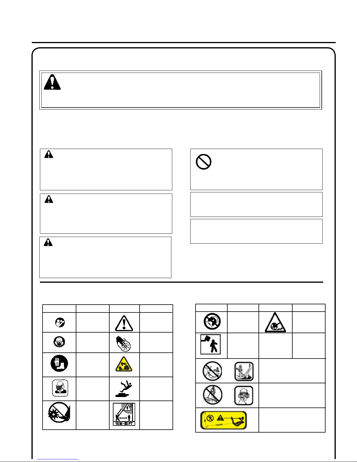
Eye Protection
Wear eye protection that meets ANSI Z87.1 or CE re-
quirements whenever you operate the trimmer.
Hand Protection
Wear no-slip, heavy duty work gloves to improve your
grip on the Trimmer/Brush Cutter handles. Gloves also
reduce the transmission of machine vibration to your
hands.
Hearing Protection
ECHO recommends wearing hearing protection whenever
unit is used.
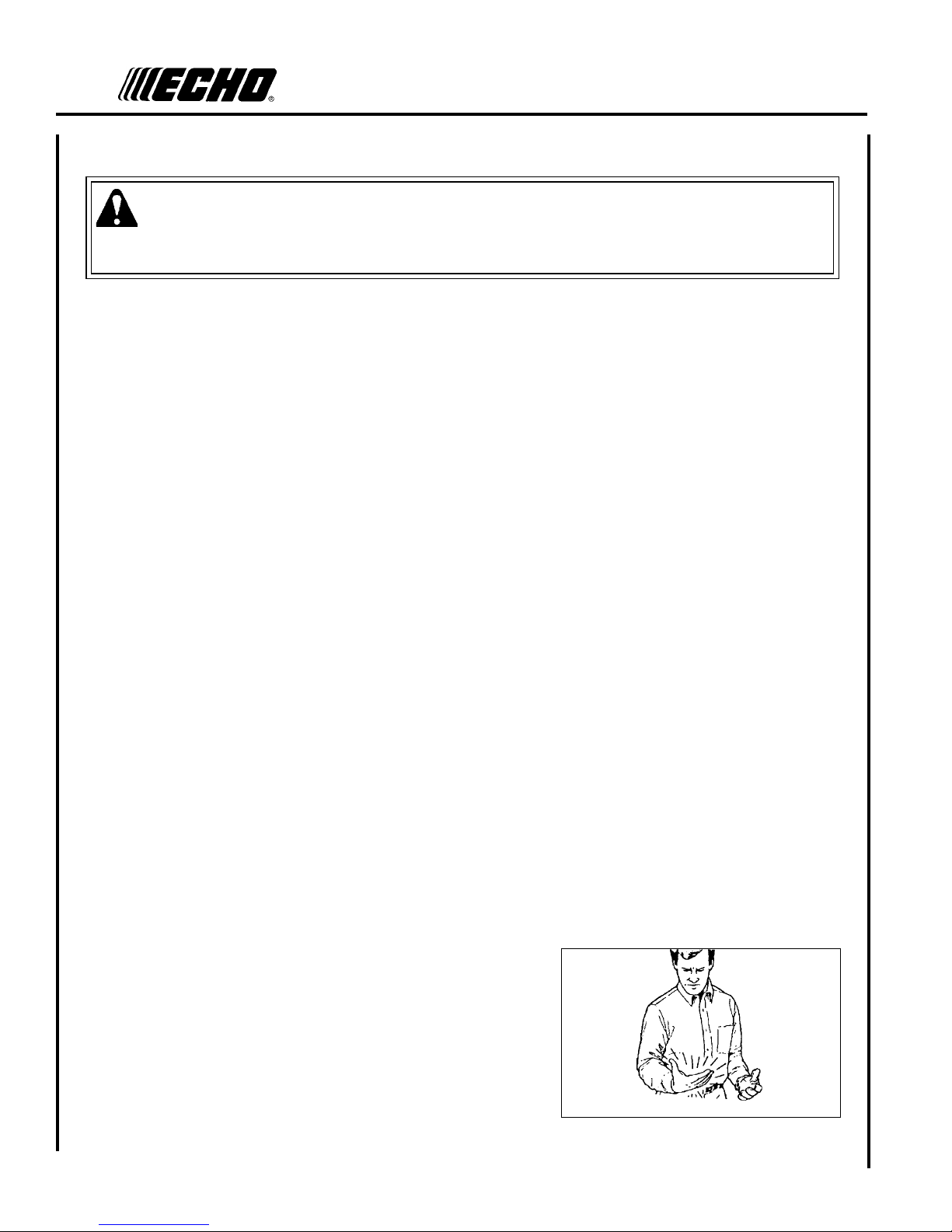
Vibration and Cold
It is believed that a condition called Raynaud’s Phenomenon, which affects the ngers of certain individuals, may be
brought about by exposure to vibration and cold. Exposure to vibration and cold may cause tingling and burning sensa-
tions, followed by loss of color and numbness in the ngers. The following precautions are strongly recommended,
because the minimum exposure which might trigger the ailment is unknown.
• Keep your body warm, especially the head, neck, feet, ankles,
hands, and wrists.
• Maintain good blood circulation by performing vigorous arm
exercises during frequent work breaks, and also by not smoking.
• Limit the hours of operation. Try to ll each day with jobs where
operating the trimmer or other hand-held power equipment is not
required.
• If you experience discomfort, redness and swelling of the ngers
followed by whitening and loss of feeling, consult your physician
before further exposing yourself to cold and vibration.
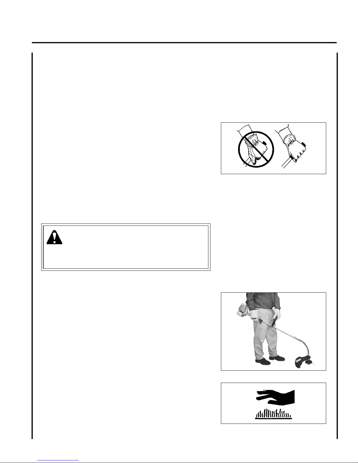
Proper Clothing
Wear snug tting, durable clothing;
• Pants should have long legs, shirts with long sleeves.
• DO NOT WEAR SHORTS,
• DO NOT WEAR TIES, SCARVES, JEWELRY,
or clothing with loose or hanging items that could
become entangled in moving parts or surrounding
growth.
Wear sturdy work shoes with nonskid soles;
• DO NOT WEAR OPEN TOED SHOES,
• DO NOT OPERATE UNIT BAREFOOTED.
Wear no-slip, heavy duty work gloves.
Keep long hair away from engine and air intake. Retain
hair with cap or net.
Hot Humid Weather
Heavy protective clothing can increase operator fatigue
which may lead to heat stroke. Schedule heavy work for
early morning or late afternoon hours when temperatures
are cooler.