Echo SRM-225U User manual

Specifications, descriptions and illustrative material in this literature are as accurate as known at the time
of publication, but are subject to change without notice. Illustrations may include optional equipment and
accessories, and may not include all standard equipment.
Operator’s Manual
X7722271407
© 4/2013 ECHO Inc.
x7722271404 / x772000164
SRM-225U
GRASS TRIMMER /
BRUSH CUTTER
Burn Hazard
The muffler or catalytic muffler and surrounding cover may become extremely hot.
Always keep clear of exhaust and muffler area, otherwise serious personal injury may
occur.
The engine exhaust from this product contains chemicals known to the State of California to cause
cancer, birth defects or other reproductive harm.
Users of this equipment risk injury to themselves and others if the unit is used
improperly and/or safety precautions are not followed. ECHO provides an operator’s
manual and a safety manual. Both must be read and understood for proper and safe
operation. Failure to do so could result in serious injury.

2X7722271407
© 4/2013 ECHO Inc.
TABLE OF CONTENTS SRM-225U
TABLE OF CONTENTS
Table of Contents .............................................................................................................................. 2
Introduction ........................................................................................................................................ 4
The Operator’s Manual ................................................................................................................ 4
The Safety Manual....................................................................................................................... 4
Servicing Information ......................................................................................................................... 4
Parts/Serial Number..................................................................................................................... 4
Service......................................................................................................................................... 4
Echo Consumer Product Support ................................................................................................ 4
Warranty Registration .................................................................................................................. 4
Additional or Replacement Manuals ............................................................................................ 5
Safety................................................................................................................................................. 5
Manual Safety Symbols and Important Information..................................................................... 5
International Symbols .................................................................................................................. 6
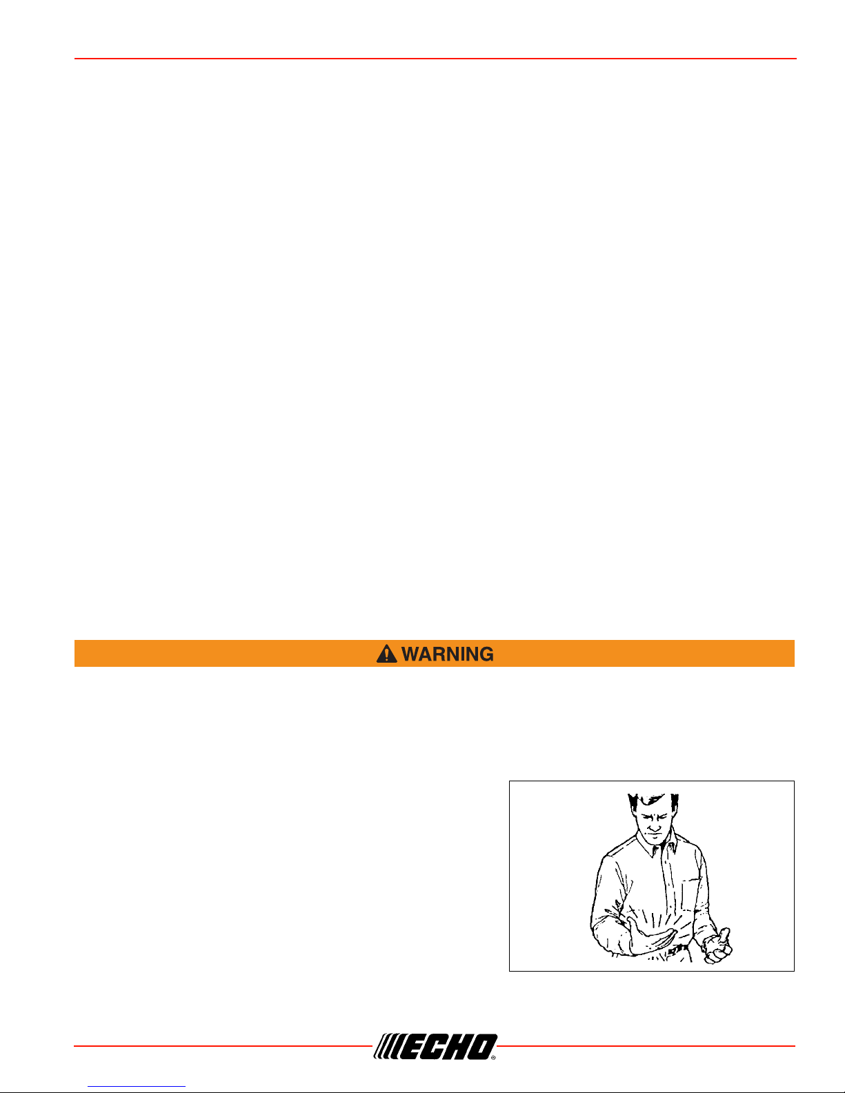
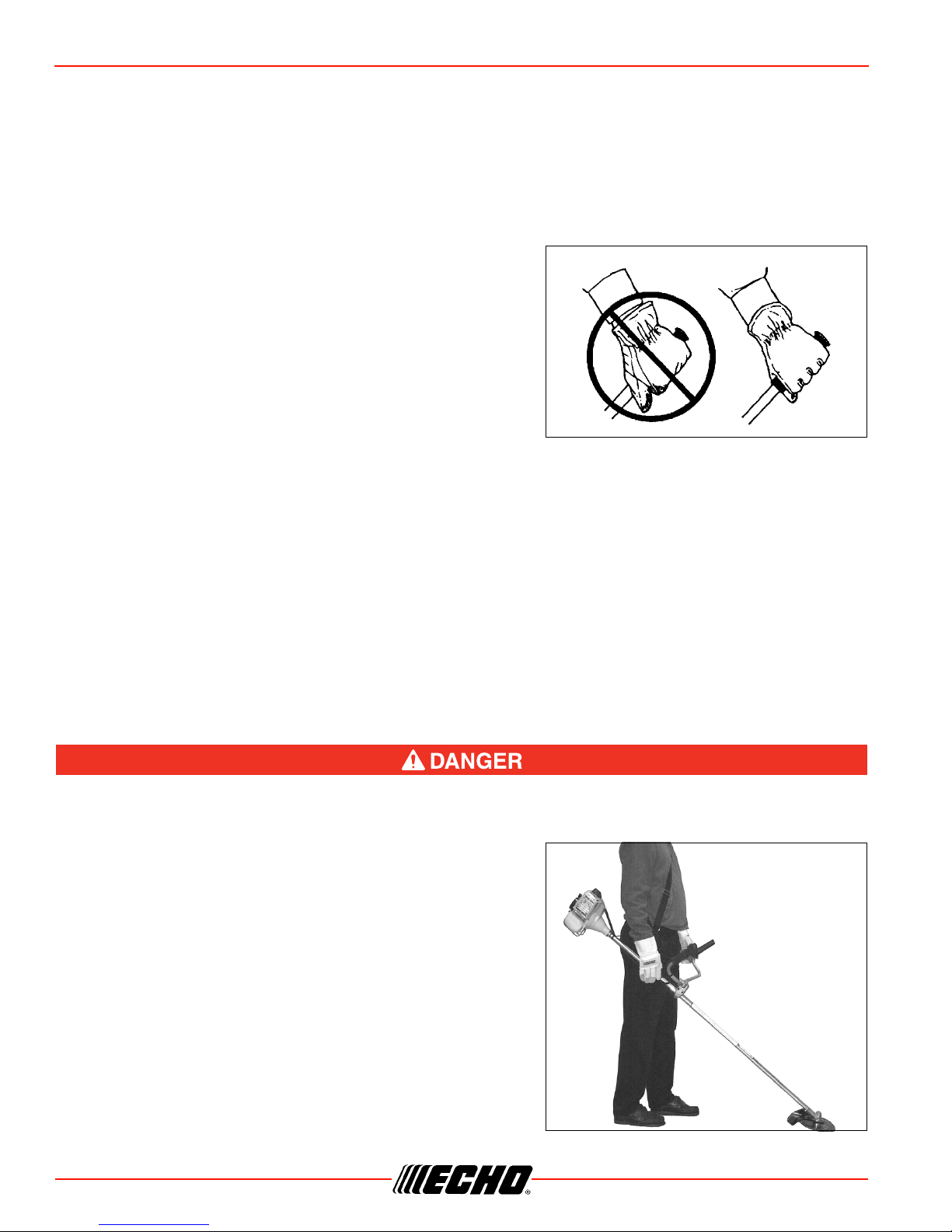
Personal Condition and Safety Equipment .................................................................................. 6
Equipment.................................................................................................................................... 9
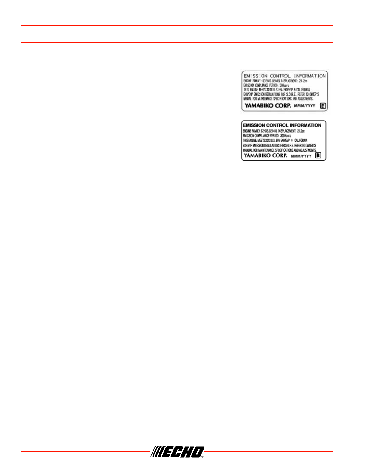
Emission Control (Exhaust & Evaporative)...................................................................................... 10
EPA 2010 and Later and/or C.A.R.B. TIER III ........................................................................... 10
Description....................................................................................................................................... 11
Contents .......................................................................................................................................... 13
Assembly ......................................................................................................................................... 14
Plastic Shield Installation ........................................................................................................... 14
Nylon Line Head Installation ...................................................................................................... 14
To Advance Trimmer Line.......................................................................................................... 15
Remove Nylon Line Head.......................................................................................................... 15
Blade Installation........................................................................................................................ 15
U-Handle Installation.................................................................................................................. 17
Throttle Linkage and Ignition Leads........................................................................................... 17
Balance and Adjust Unit............................................................................................................. 18
Operation ......................................................................................................................................... 19
Operation With Blades............................................................................................................... 19
Blade Selection.......................................................................................................................... 20
Fuel............................................................................................................................................ 21
Starting Cold Engine.................................................................................................................. 23
Starting Warm Engine................................................................................................................ 24
Stopping Engine......................................................................................................................... 24
Maintenance .................................................................................................................................... 25
Skill Levels................................................................................................................................. 25
Maintenance Intervals................................................................................................................ 25
Air Filter...................................................................................................................................... 26
Fuel Filter................................................................................................................................... 26
Spark Plug ................................................................................................................................. 27
Cooling System.......................................................................................................................... 27
Exhaust System......................................................................................................................... 28
Carburetor Adjustment............................................................................................................... 29
Lubrication ................................................................................................................................. 30
Nylon Line Head Disassembly Instructions................................................................................ 31
Nylon Line Replacement............................................................................................................ 31
Sharpening Metal Blades........................................................................................................... 32
Troubleshooting ............................................................................................................................... 34

SRM-225U TABLE OF CONTENTS
X7722271407 3
© 4/2013 ECHO Inc.
Storage ............................................................................................................................................ 35
Long Term Storage (Over 30 Days)........................................................................................... 35
Specifications................................................................................................................................... 36
Warranty Statements ....................................................................................................................... 37
Notes................................................................................................................................................ 39

4X7722271407
© 4/2013 ECHO Inc.
INTRODUCTION SRM-225U
INTRODUCTION
Welcome to the ECHO family. This ECHO product was designed and manufactured to provide long life and
on-the-job dependability. Read and understand this manual and the SAFETY MANUAL. You will find both
easy to use and full of helpful operating tips and SAFETY messages.
The Operator’s Manual
Keep it in a safe place for future reference. Contains specifications and information for safety, operation,
maintenance, storage and assembly specific to this product.
The Safety Manual
Keep it in a safe place for future reference. Explains possible hazards and the measures you should take to
insure safe operation.
SERVICING INFORMATION
Parts/Serial Number
Genuine ECHO Parts and ECHO REPOWER™ Parts and
Assemblies for your ECHO products are available only from an
Authorized ECHO Dealer. When you do need to buy parts always
have the Model Number and Serial Number of the unit with you.
You can find these numbers on the engine housing. For future
reference, write them in the space provided below.
Model No. _________________ SN. ___________________
Service
Service of this product during the warranty period must be performed by an Authorized ECHO Service
Dealer. For the name and address of the Authorized ECHO Service Dealer nearest you, ask your retailer or
call: 1-800-432-ECHO (3246). Dealer information is also available on our Web Site. When presenting your
unit for Warranty service/repairs, proof of purchase is required.
Echo Consumer Product Support
If you require assistance or have questions concerning the application, operation or maintenance of this
product you may call the ECHO Consumer Product Support Department at 1-800-673-1558 from 8:30 am to
4:30 pm (Central Standard Time) Monday through Friday. Before calling, please know the model and serial
number of your unit.
Warranty Registration
To ensure trouble free warranty coverage it is important that you register your ECHO equipment on-line at
www.echo-usa.com or by filling out the warranty registration card supplied with your unit. Registering your
product confirms your warranty coverage and provides a direct link between you and ECHO if we find it
necessary to contact you.

SRM-225U SAFETY
X7722271407 5
© 4/2013 ECHO Inc.
Additional or Replacement Manuals
Replacement Operator, Safety Manuals, and Parts Catalogs are available from your ECHO dealer or at
www.echo-usa.com or by contacting ECHO Inc., 400 Oakwood Road, Lake Zurich, IL 60047
(800-673-1558). Always check the ECHO Web Site for updated information.
Safety Videos are available from your Echo dealer. A $5.00 shipping charge will be required for each video.
SAFETY
Manual Safety Symbols and Important Information
Throughout this manual and on the product itself, you will find safety alerts and helpful, informational
messages preceded by symbols or key words. The following is an explanation of those symbols and key
words and what they mean to you.
The safety alert symbol accompanied by the word “DANGER” calls attention to an act or condition
which WILL lead to serious personal injury or death if not avoided.
The safety alert symbol accompanied by the word “WARNING” calls attention to an act or condition
which CAN lead to serious personal injury or death if not avoided.
The safety alert symbol accompanied by the word “CAUTION” calls attention to an act or condition
which may lead to minor or moderate personal injury if not avoided.
The enclosed message provides information necessary for the protection of the unit.
Note: This enclosed message provides tips for use, care and maintenance of the unit.
CIRCLE AND SLASH SYMBOL
This symbol means the specific action shown is prohibited. Ignoring these prohibitions can result
in serious or fatal injury.

6X7722271407
© 4/2013 ECHO Inc.
SAFETY SRM-225U
International Symbols
Personal Condition and Safety Equipment
Users of this product risk injury to themselves and others if the unit is used improperly and/or safety
precautions are not followed. Proper clothing and safety gear must be worn when operating unit.
Physical Condition
Your judgment and physical dexterity may not be good:
• if you are tired or sick,
• if you are taking medication,
• if you have taken alcohol or drugs.
Operate unit only if you are physically and mentally well.
Eye Protection
Eye protection that meets ANSI Z87.1 or CE requirements must be worn whenever you operate the unit.
Symbol Description Symbol Description Symbol Description Symbol Description
Warning, See
Operator’s
Manual
Carburetor
Adjustment -
High speed
mixture
DO NOT allow
flames or
sparks near fuel
Ignition
ON / OFF
Wear eye, ear
and head
protection
Carburetor
Adjustment -
Idle speed
DO NOT smoke
near fuel Primer Bulb
Wear hand
and foot
protection
Carburetor
Adjustment -
Low speed
mixture
Choke Control
“Run” Position
(Choke Open)
Choke Control
“Cold Start”
Position (Choke
Closed)
Safety/Alert Emergency
Stop
Keep feet away
from blade
RotatingCutting
Attachment
Hot Surface Fuel and oil
mixture
Keep bystanders and helpers
away 15 m (50 ft.).
A V O I D K I C K O U T .
Keep bystanders at least 15 meters
(50 feet) away.
Thrown
objects
Direction of
blade
Beware Thrown Obje ct s
Wear Eye Protection

SRM-225U SAFETY
X7722271407 7
© 4/2013 ECHO Inc.
Hand Protection
Wear no-slip, heavy duty work gloves to improve your grip on the handles. Gloves also reduce the
transmission of machine vibration to your hands.
Breathing Protection
Wear a facemask to protect against dust.
Hearing Protection
ECHO recommends wearing hearing protection whenever unit is used.
Proper Clothing
Wear snug fitting, durable clothing;
• Pants should have long legs, shirts with long sleeves.
• DO NOT WEAR SHORTS,
• DO NOT WEAR TIES, SCARVES, JEWELRY, or clothing with loose or hanging items that could become
entangled in moving parts or surrounding growth.
Wear sturdy work shoes with nonskid soles;
• DO NOT WEAR OPEN TOED SHOES,
• DO NOT OPERATE UNIT BAREFOOTED.
Wear no-slip, heavy duty work gloves.
Keep long hair away from engine and air intake. Retain hair with cap or net.
Hot Humid Weather
Heavy protective clothing can increase operator fatigue which may lead to heat stroke. Schedule heavy
work for early morning or late afternoon hours when temperatures are cooler.
The ignition componentsof this machine generate an electromagnetic fieldduring operation which
may interfere with some pacemakers.To reduce the risk of serious or fatal injury, persons with
pacemakers should consult with their physician and the pacemaker manufacturer before operating
this machine.In the absence of such information, ECHO does not recommend the use ofECHO
products by anyonewho has a pacemaker.
Vibration and Cold
It is believed that a condition called Raynaud’s Phenomenon,
which affects the fingers of certain individuals, may be brought
about by exposure to vibration and cold. Exposure to vibration
and cold may cause tingling and burning sensations, followed
by loss of color and numbness in the fingers. The following
precautions are strongly recommended, because the minimum
exposure, which might trigger the ailment, is unknown.
• Keep your body warm, especially the head, neck, feet, ankles,
hands, and wrists.

8X7722271407
© 4/2013 ECHO Inc.
SAFETY SRM-225U
• Maintain good blood circulation by performing vigorous arm exercises during frequent work breaks, and
also by not smoking.
• Limit the hours of operation. Try to fill each day with jobs where operating the unit or other hand-held
power equipment is not required.
• If you experience discomfort, redness, and swelling of the fingers followed by whitening and loss of feeling,
consult your physician before further exposing yourself to cold and vibration.
Repetitive Stress Injuries
It is believed that overusing the muscles and tendons of the
fingers, hands, arms, and shoulders may cause soreness,
swelling, numbness, weakness, and extreme pain in those
areas. Certain repetitive hand activities may put you at a high
risk for developing a Repetitive Stress Injury (RSI). An extreme
RSI condition is Carpal Tunnel Syndrome (CTS), which could
occur when your wrist swells and squeezes a vital nerve that
runs through the area. Some believe that prolonged exposure to
vibration may contribute to CTS. CTS can cause severe pain for
months or even years.
To reduce the risk of RSI/CTS, do the following:
• Avoid using your wrist in a bent, extended, or twisted position. Instead try to maintain a straight wrist
position. Also, when grasping, use your whole hand, not just the thumb and index finger.
• Take periodic breaks to minimize repetition and rest your hands.
• Reduce the speed and force with which you do the repetitive movement.
• Do exercise to strengthen the hand and arm muscles.
• Immediately stop using all power equipment and consult a doctor if you feel tingling, numbness, or pain in
the fingers, hands, wrists, or arms. The sooner RSI/CTS is diagnosed, the more likely permanent nerve
and muscle damage can be prevented.
Do not operate this product indoors or in inadequately ventilated areas. Engine exhaust contains
poisonous emissions and can cause serious injury or death.
Read the Manuals
• Provide all users of this equipment with the Operator’s Manual
and Safety Manual for instructions on Safe Operation.
Clear the Work Area
• Spectators and fellow workers must be warned, and children
and animals prevented from coming nearer than 15 m (50 ft.)
while the unit is in use.
Keep a Firm Grip
• Hold both handles with thumbs and fingers encircling the
grips.

SRM-225U SAFETY
X7722271407 9
© 4/2013 ECHO Inc.
Keep a Solid Stance
• Maintain footing and balance at all times. Do not stand on slippery, uneven or unstable surfaces. Do not
work in odd positions or on ladders. Do not over reach.
Avoid Hot Surfaces
• Keep exhaust area clear of flammable debris. Avoid contact
during and immediately after operation.
Equipment
Use only ECHO approved attachments. Serious injury may result from the use of a non-approved
attachment combination. ECHO, INC. will not be responsible for the failure of cutting devices,
attachments or accessories which have not been tested and approved by ECHO. Read and comply
with all safety instructions listed in this manual and safety manual.
• Check unit for loose/missing nuts, bolts, and screws. Tighten and/or replace as needed.
• Inspect shield for damage and ensure that the cut-off knife is securely in place. Replace if either is
damaged or missing.
• Check that the cutting attachment is firmly attached and in safe operating condition.
• Check that handle and harness (if included) are adjusted for safe, comfortable operation. See Assembly
Section for proper adjustment.
Moving parts can amputate fingers or cause severe injuries. Keep hands, clothing and loose objects
away from all openings.
◆ALWAYS stop engine, disconnect spark plug, and make sure all moving parts have come to a complete
stop before removing obstructions, clearing debris, or servicing unit.
DO NOT start or operate unit unless all guards and protective covers are properly assembled to unit.
NEVER reach into any opening while the engine is running. Moving parts may not be visible through
openings.
Check fuel system for leaks due to fuel tank damage, especially if the unit is dropped. If damage or
leaks are found, do not use unit, otherwise serious personal injury or property damage may occur.
Have unit repaired by an authorized servicing dealer before using.

10 X7722271407
© 4/2013 ECHO Inc.
EMISSION CONTROL (EXHAUST & EVAPORATIVE) SRM-225U
EMISSION CONTROL (EXHAUST & EVAPORATIVE)
EPA 2010 and Later and/or C.A.R.B. TIER III
The emission control system for the engine is EM (engine modification)
and, if the second to last character of the Engine Family on the Emission
Control Information label (sample below) is “C”, “K”, or “T”, the emission
control system is EM and TWC (3-way catalyst). The fuel tank/fuel line
emission control system is EVAP (evaporative emissions). Evaporative
emissions for California models are only applicable to fuel tanks.
An Emission Control Label is located on the engine. (This is an
EXAMPLE ONLY, information on label varies by engine FAMILY).
Product Emission Durability (Emission Compliance Period)
The 50 or 300 hour emission compliance period is the time span
selected by the manufacturer certifying the engine emissions output
meets applicable emissions regulations, provided that approved
maintenance procedures are followed as listed in the Maintenance Section of this manual.

SRM-225U DESCRIPTION
X7722271407 11
© 4/2013 ECHO Inc.
DESCRIPTION
Locate the safety decal(s) on your unit. Make sure the decal(s) is legible and that you understand and follow
the instructions on it. If a decal cannot be read, a new one can be ordered from your ECHO dealer. See
PARTS ORDERING instructions for specific information.
1
2
3
4
5
6
7
89
10
11
12
13
14 15
16
17
18
19
20
21
22
Hot LabelShaft Label
Metal Shield Label

12 X7722271407
© 4/2013 ECHO Inc.
DESCRIPTION SRM-225U
1. POWER HEAD - Includes the Engine, Clutch, Fuel System, Ignition System and Recoil Starter.
2. THROTTLE TRIGGER LOCKOUT - This lever must be held during starting. Operation of the throttle
trigger is prevented unless throttle trigger lockout lever is engaged.
3. STOP SWITCH - “SLIDE SWITCH” mounted on top of the Throttle Trigger Housing. Move switch
FORWARD to RUN, BACK to STOP.
4. THROTTLE TRIGGER - Controls engine speed. Spring loaded to return to idle when released. During
acceleration, press trigger gradually for best operating technique.
5. DRIVE SHAFT ASSEMBLY - Includes the Rear (right hand) Handle assembly, Gear Housing assembly,
Front (loop, left hand) Handle assembly, metal drive shaft and Safety Decal.
6. NYLON CUTTER HEAD - Contains replaceable nylon trimming line that advances when the trimmer
head is tapped against the ground while the head is turning at normal operating speed.
7. CUT-OFF KNIFE - Automatically trims line to the correct length: 5" after head is tapped on the ground. If
trimmer is operated without a cut-off knife, the line will become too long, the engine will overheat, and
engine damage may occur.
8. PLASTIC DEBRIS SHIELD ASSEMBLY - Included in plastic bag (co-pack). MUST be installed on unit
before use, see Assembly Instructions. Shield assembly includes the Cut-Off Knife. Mounts on the Gear
Housing Assembly just above the cutting attachment. Helps protect the operator by deflecting debris
produced during the trimming operation. This shield must be replaced with the metal shield for blade
use.
9. U-HANDLE - Required for metal blade operation.
10. HIP PAD - Used to protect hip/leg and clothing when using U-handle equipped unit.
11. SHOULDER HARNESS - An adjustable strap that suspends the unit from the operator. Using the strap
reduces operator fatigue.
12. BLADE - Circular blade for grass, weed or brush cutting applications. Harness, metal shield &
U-handles required for blade operation.
13. METAL BLADE SHIELD - Required when unit is equipped with blades. Do not operate unit without
shield.
14. SPARK PLUG - Provides spark to ignite fuel mixture.
15. ARM REST - Provides arm rest during operation and protects arm from the hot engine.
16. RECOIL STARTER HANDLE - Pull handle slowly until starter engages, then quickly and firmly. When
engine starts, return handle slowly. DO NOT let handle snap back or damage to unit will occur.
17. SPARK ARRESTOR MUFFLER OR SPARK ARRESTOR MUFFLER WITH CATALYST - The muffler
or catalytic muffler controls exhaust noise and emission. The spark arrestor screen prevents hot, glowing
particles of carbon from leaving the muffler. Keep exhaust area clear of flammable debris.
18. FUEL TANK - Contains fuel and fuel filter.
19. FUEL TANK CAP - Covers and seals fuel tank opening.
20. CHOKE - The choke control is located at the rear of the air cleaner housing. Move choke lever to Cold
Start ( ) to close choke for cold start. Move choke lever to “Run” ( ) position to open choke.
21. AIR CLEANER - Contains replaceable filter element.
22. PURGE BULB - Pumping purge bulb before starting engine draws fresh fuel from the fuel tank, purging
air from the carburetor. Pump purge bulb until fuel is visible and flows freely in the clear fuel tank return
line. Pump purge bulb an additional 4 or 5 times.

SRM-225U CONTENTS
X7722271407 13
© 4/2013 ECHO Inc.
CONTENTS
The ECHO product you purchased has been factory pre-assembled for your convenience. Due to packaging
restrictions, shield installation and other assembly may be necessary.
After opening the carton, check for damage. Immediately notify your retailer or ECHO Dealer of damaged or
missing parts. Use the contents list to check for missing parts.
____ - 1 - Power Head / Drive Shaft Assembly
____ - 1 - U-handle assembly
____ - 1, Operator’s Manual
____ - 1, Safety Manual
____ - 1, Warranty Registration Card
____ - 1, Emission Control Warranty Statement
____ - 1, Plastic Shield
____ - Assembly Tool(s)
____ - 1, Nylon Trimmer Head
____ - 1, 8 Tooth Weed/Grass Blade
____ - 1, Safety Glasses
____ - 1, Echo Power Blend XTM 2-Stroke Oil Sample
____ - 1, Shield Plate
____ - 3, 5mm x 16mm Screws (shield mounting)
____ - 1, 8mm x 55mm Bolt
____ - 1, Flat Washer
____ - 2, Cable Clips
____ - 3, 5mm x 10mm Screws (shield mount)
____ - 2, 5mm x 8mm Screws (bracket to shield)
____ - 4, 5mm Nuts
____ - 4, 5mm Lockwashers
____ - 1, Metal Shield
____ - 1, Bracket
____ - 1, Shoulder Harness w/Hip Pad
____ - 10, Cotter Pins

14 X7722271407
© 4/2013 ECHO Inc.
ASSEMBLY SRM-225U
ASSEMBLY
Plastic Shield Installation
(Nylon line operation)
The plastic shield is for use with the Nylon Line Head only.
Install Metal Shield when using plastic or metal blades, or
serious injury may result.
1. Align hole in upper plate (A) with notch in gear housing (B), and insert locking tool (G) to prevent splined
shaft from turning. Arrow on gear housing flange points to notch location.
2. Remove cotter pin (C), L.H. blade nut (D), lower plate (E),
and upper plate (A) from PTO shaft (F). Turn blade nut
clockwise to remove.
3. Remove locking tool (G). Retain lower plate (E) and blade
nut (D), for future use with blade conversions.
4. Align plastic debris shield (H) with the drive shaft, and install
on the bottom of the gear housing flange.
5. Place shield plate (I) on shield, align holes and install three
(3) screws.
6. Replace upper plate (A) on PTO shaft (F).
Nylon Line Head Installation
Wear Gloves or personal injury may result:
•Cutoff knife is sharp.
•Gearcase and surrounding area may be hot.
1. Make sure plastic debris shield (H) is properly aligned, and
upper plate (A) is installed on splined PTO shaft (F).
2. Align hole in upper plate (A) with notch in gear housing (B), and insert locking tool (G) to prevent splined
shaft from turning.
Parts Required: Plastic Debris Shield, Shield Plate,
three (3) 5 x 16 mm screws.
Parts Required: Nylon Line Head.
B
A
E
DC
F
H
I
A
G
F
A

SRM-225U ASSEMBLY
X7722271407 15
© 4/2013 ECHO Inc.
3. Thread line head (J) onto PTO shaft by turning it
counter-clockwise until head is tight against upper plate (A).
4. Remove locking tool (G).
Semi-automatic nylon line heads must be used only with plastic
debris shield with cut-off knife. Using nylon line heads with
metal debris shield can result in trimmer damage, caused by
operation with excessive line length.
Note: Your nylon line head may appear different than nylon line head shown.
To Advance Trimmer Line
See Maintenance Section for nylon line replacement.
Note: To advance trimmer line, tap trimmer head against the ground while the head is turning at normal
operating speed.
Remove Nylon Line Head
Note: Do not disassemble nylon line head.
1. Align locking hole in upper plate with notch in edge of gear
housing and insert head locking tool (G).
2. Remove line head (J) by turning it clockwise until head is
completely off of shaft.
3. Remove locking tool (G).
Blade Installation
You must install the U-Handle and all Blade Conversion parts shown in the following instructions
before operating this unit with a metal blade, otherwise serious injury may result.
Note: Model SRM-225U includes U-Handle, 8-tooth blade, and necessary blade conversion parts. Blades
must be selected for type of cutting being performed. See “Blade Selection.”
Install Metal Shield
1. If installed remove nylon line head, upper fixing plate, shield
plate, and plastic shield.
Parts Required: Metal Shield, Shield Bracket,
3 - 5 x 10 mm screws (metal shield
to gear housing).
2 - 5 x 8 mm screws, 2 - 5 mm nuts,
2 - 5 mm lockwashers, (bracket to
shield).
2 - 5 mm nuts, 2 - 5 mm lockwashers
(bracket to gear housing)
G
J
G
J
HG
J

16 X7722271407
© 4/2013 ECHO Inc.
ASSEMBLY SRM-225U
a. Align locking hole in upper plate with notch in edge of gear housing and insert head locking tool (G).
b. Remove line head (J) by turning it clockwise until head is completely off of shaft.
c. Remove locking tool (G).
d. Remove three screws holding shield plate and plastic shield (H) to gear housing.
e. Retain line head, upper fixing plate, shield plate, and plastic shield for conversion back to nylon line
head operation.
2. Align hole in upper plate (A) with notch in gear housing (B),
and insert locking tool to prevent splined shaft from turning.
Arrow on gear housing flange points to notch location.
3. Remove split pin (C), L.H. blade nut (D), lower plate (E), and
upper plate (A) from PTO shaft (F). Turn blade nut
clockwise to remove.
4. Remove locking tool (G).
5. Loosely attach bracket (K) to shield (L) and attach shield to
bottom of gear housing (B) with hardware provided.
6. Tighten all shield hardware.
Install Blade
1. Install upper plate (A) on splined PTO shaft, pilot side down.
Blade installation requires Upper Plate (A) with 20 mm pilot.
2. Install Blade (M) on upper plate pilot. Blades must be
installed so that rotation arrow on blade matches rotation of
unit: teeth toward direction of rotation (See debris shield
decal). Secure blade with Lower Plate (E), and 10 mm L.H.
nut (D). Turn nut counter-clockwise on PTO shaft to tighten.
3. Align hole in upper plate with notch in gear housing, and
insert Locking Tool (G) to prevent splined shaft from turning.
Arrow on gear housing points to notch. Tighten 10 mm nut
securely.
Parts Required: Upper Plate w/ 20 mm pilot, Lower Plate, 10
mm Nut w/L.H. threads, 2 x 25 mm Cotter Pin,
Blade.
A
B
C
D
E
F
K
L
B
A
G
M
ED
C

SRM-225U ASSEMBLY
X7722271407 17
© 4/2013 ECHO Inc.
4. Insert Cotter Pin (C) in hole in PTO shaft, and bend pin legs
around shaft counterclockwise to retain 10 mm nut.
Never reuse a cotter pin - install a new cotter pin each time a
blade is installed or replaced.
5. Remove locking tool (G).
U-Handle Installation
1. Install upper U-Handle and bracket on lower bracket with
one (1) 8mm x 55mm bolt (N) and (1) large circular washer.
Do not tighten bolt securely until final adjustments are
completed.
2. Loosen upper (2) U-handle clamp screws (O), and position
U-handle as shown.
3. Lightly tighten 8mm bolt (N) and clamp screws (O) to hold
U-handle in position until final adjustments are completed.
4. Route throttle linkage and ignition lead assembly along shaft and clip as shown.
5. Install throttle linkage cable into fan cover clip (C), if
required.
Throttle Linkage and Ignition Leads
1. Close choke and remove air filter cover.
2. Place throttle linkage (A) into adjustment fixture (B) and
install wire end into large carburetor throttle swivel hole (C).
Check throttle for freedom of movement and that wide open
throttle / low idle extremes are adjusted properly. The
throttle linkage must be adjusted by moving the adjustment
nut (D). Consult with your Echo Dealer for correct
adjustment procedure.
3. Tighten nut (E).
Parts Required: U-Handle, Clamp w/screws, 8 mm x 55 mm hex
bolt, 8 mm flat washer
AG
ME
DC
N
O
C
A
B
C
D
E

18 X7722271407
© 4/2013 ECHO Inc.
ASSEMBLY SRM-225U
4. Connect 2 ignition stop leads (F, G) from throttle cable
tubing to 2 ignition leads (F, G) on engine.
5. Secure ignition leads against engine housing with clips
(H, I).
6. Install air filter and cover.
Balance and Adjust Unit
1. Loosen harness clamp screw.
2. Put on harness and attach unit to harness.
3. Slide harness clamp up (A) or down until unit balances with
head approximately 50-75 mm (2-3 in.) from the ground.
4. Tighten harness clamp screw.
5. Loosen upper U-Handle clamp screws (B), and position
U-Handle for comfortable operation.
6. Tighten U-Handle clamp screws and 8 mm clamp bolt
securely.
F
G
H
I
B
A

SRM-225U OPERATION
X7722271407 19
© 4/2013 ECHO Inc.
OPERATION
Moving parts can amputate fingers or cause severe injuries. Keep hands, clothing and loose objects
away from all openings. Always stop engine, disconnect spark plug, and make sure all moving parts
have come to a complete stop before removing obstructions, clearing debris, or servicing unit.
Engine exhaust IS HOT, and contains Carbon Monoxide (CO), a poison gas. Breathing CO can cause
unconsciousness, serious injury, or death. Exhaust can cause serious burns. ALWAYS position unit
so that exhaust is directed away from your face and body.
Operation of this equipment may create sparks that can start fires. This unit is equipped with a spark
arrestor to prevent discharge of hot particles from the engine. Metal cutters can also create sparks if
the cutter strikes rocks, metal, or other hard objects. Contact local fire authorities for laws or
regulations regarding fire prevention requirements.
Operation With Blades
Blade use DEMANDS specific Brush Cutter configuration. Operation without specified shield, barrier
bar or U-handle, and harness can result in serious personal injury. Follow installation instructions.
DO NOT INSTALL BLADES ON GT (CURVED SHAFT) MODEL TRIMMERS.
• Arbor Diameter of Upper Blade Plate must match arbor diameter of blades.
• New cotter pin required each time blade is installed.
• Brush cutters over 16.5 lbs (7.5 kg) dry weight (weight w/o fuel) require a double shoulder harness.
TO USE
THESE
BLADES
Pro Maxi-Cut
Grass/Weed
Blade
Rigid Plastic
Tri-Cut
Grass/Weed Blade
Metal Blade
You
must
install
these
parts!
Loop Handle, w/or
w/o Barrier Bar
U-Handle or Loop Handle
w/Barrier Bar
U-Handle or Loop Handle
w/Barrier Bar
Plastic Shield Plastic Shield Metal Shield
Harness Harness Harness
Upper Plate &
Flat Washer
Upper Plate
& Glide Cup
Upper/Lower
Blade Plates
Hex Nut Hex Nut Hex Nut
New Cotter Pin New Cotter Pin New Cotter Pin

20 X7722271407
© 4/2013 ECHO Inc.
OPERATION SRM-225U
Note: The Barrier Bar is used to restrict rearward movement of the unit. The Barrier Bar is NOT A HANDLE
and should not be gripped when using or carrying the unit.
Blade Selection
The type of Blade used MUST be matched to the type and size of material cut. An improper or dull
blade can cause serious personal injury. Blades MUST be sharp. Dull blades increase the chance of
kick-out and injury to yourself and bystanders.
Plastic/Nylon Grass/Weed Blades may be used where ever
the nylon line head is used. DO NOT use this blade for heavy
weeds or brush!
8 Tooth Weed/Grass Blade is designed for grass, garden
debris and thick weeds up to 19 mm (3/4”) diameter. DO NOT
use this blade for brush or heavy woody growth.
80 Tooth Brush Blade is designed for cutting brush and woody
growth up to 13 mm (1/2 in.) diameter.
22 Tooth Clearing Blade is designed for dense thickets and
saplings up to 64 mm (2-1/2 in.) diameter.
Use Shoulder/Waist Harness Use of the Shoulder/Waist
Harness is recommended for ALL Trimmer/Brush Cutter use,
not just Blade operation. The Shoulder/Waist Harness when
used in a trimming operation with nylon line head suspends the
trimmer from the operator's shoulder and reduces operator
fatigue.
During blade operation, the same fatigue reduction is achieved.
Safety to the operator is also enhanced by reducing the
possibility of blade contact with the operator's hands and feet by
restricting trimmer movement.
Other manuals for SRM-225U
3
Table of contents
Other Echo Trimmer manuals

Echo
Echo RM-4000 User manual

Echo
Echo RM-410ES User manual

Echo
Echo SRM-260 - PARTS CATALOG SERIAL NUMBERS... Instruction Manual

Echo
Echo HCA-2620ES-HD User manual

Echo
Echo GT-251E User manual

Echo
Echo SRM-2400 TYPE 1E - 09-99 User manual

Echo
Echo GT-225 User manual

Echo
Echo SRM-400 User manual

Echo
Echo GT-200i User manual

Echo
Echo HC-2410 User manual

Echo
Echo SRM-211i User manual

Echo
Echo HCA-2620 User manual

Echo
Echo GT-1000 User manual

Echo
Echo GT-230 User manual

Echo
Echo SRM-266 User manual

Echo
Echo DHCS-2800 User manual

Echo
Echo DSRM-200 User manual

Echo
Echo WT190 User manual

Echo
Echo SRM-2400 TYPE 1E - PARTS CATALOG SERIAL NUMBER... Instruction Manual

Echo
Echo SRM-210U User manual