echoflex E-VAC-SR User manual

Echoflex Installation Guide
Elaho Vacancy Sensor
Main Office nSquamish, BC, Canada nToll Free +888 324 6359 nPhone +778 733 0111 nFax +604 815 0078
Email info@echoflexsolutions.com nWeb echoflexsolutions.com nProduct information and specifications subject to change.
© 2018 Echoflex Solutions, Inc. nEchoflex intends this document to be provided in its entirety.
8186M2182 nRevision A nReleased 2018-09
Overview
The Elaho Vacancy Sensor is a ceiling mounted sensor that utilizes passive
infrared (PIR) technology, providing reliable vacancy detection for lighting
control. The sensor relies on local station control for manual on and provides
auto off functionality upon detection of vacancy.
The Vacancy Sensor provides 360 degree coverage of the
installed location and is available in three models:
•
E-VAC-SR- Vacancy Sensor with small room lens
covers 450 sq. ft. at 8 ft./ 800 sq. ft. at 10 ft.
•
E-VAC - Vacancy Sensor with standard room lens
covers 1,800 sq. ft. at 8 ft./ 3,000 sq. ft. at 10 ft.
•
E-VAC-HC - Vacancy Sensor with high ceiling lens
covers 300 sq. ft. at 10 ft./ 7,000 sq. ft. at 40 ft.
Each sensor is available in white or black finish. Lens
masks are provided to allow customized vacancy
detection fields as required by each installation.
Custom Configuration
This document guides you through the installation and local configuration of
the Vacancy Sensor. For more detailed information about custom
configuration options available for the Vacancy Sensor using ElahoAccess,
reference the ElahoAccess Mobile App integrated help system.
Note: To use the configuration settings applied using ElahoAccess, DIP
switch 2 must be enabled. Reference DIP Switch Settings on page7.

Echoflex Installation Guide
Elaho Vacancy Sensor
Wire Specification
Sensors connect to the EchoConnect®communication bus. EchoConnect is a
bidirectional protocol that uses one pair of wires (data + and data -) for both
data and power. Echoflex recommends using Belden 8471 (or approved equal)
Class 2 wire. The total combined length of an EchoConnect wire run (using
Belden 8471, or equal) may not exceed 1,640 feet (500 m).
Note: All control wiring should be installed and terminated by a
qualified installer and should follow standard wiring installation practices.
Leave approximately 8" (20cm) of wiring in the back box for connection
and to allow slack for future service needs.
Note: Echoflex requires that all Elaho stations and devices be grounded
for ESDprotection. Pull an additional 14AWG (2.5 mm2) wire for
grounding when control wires are not installed in grounded metal conduit.
Note: When using Category 5 (or equivalent) cable on the EchoConnect
communication bus, please note the following:
•
Cat5 wiring must be terminated using EchoConnect Cat5
Termination Kit and must be installed using a bus topology.
Refer to the installation guide that is provided with the Cat5
Termination Kit (8186A1207) for information to terminate
Cat5 wiring.
•
Not all topologies are supported using Cat5; careful planning
is required to ensure the proper termination kits are available
and the wire is pulled appropriately.
Installation Environment
Vacancy Sensors are intended for installation to a finished ceiling surface,
ceiling tile mounted, attached to a round fixture junction box or single-gang
RACO switch box.
The sensor operates in ambient temperatures of 0° C to 40° C, with a
maximum of 90% non-condensing humidity.
Echoflex recommends paying special attention to the installation
environment:
•
The sensor must have an unobstructed view of the room. Do not
mount behind or near tall cabinets, shelves, hanging light fixtures, etc.
•
Do not install the sensor within eight feet from an HVAC airflow
duct/vent.
Elaho Vacancy Sensor Page 2 of 12 Echoflex Solutions, Inc.

Echoflex Installation Guide
Elaho Vacancy Sensor
•
Install the sensor where it cannot easily sense movement in areas
outside of the intended space, such as hallways, glass partitions, or
adjacent rooms. If the installation location cannot avoid these
conditions, portions of the lens can be masked to block the sensor
view of these undesired areas. Reference
Lens Masking on page9
.
Parts and Supplies
The following parts and supplies are included with the Vacancy Sensor
ordered:
•
Soft ceiling tile adaptor
•
2 each screws, 6-32 x 3/4” and 1 3/4”
•
EchoConnect and ESD ground wire pigtails
•
3 lens masks
Note: Follow all local code requirements for terminating wire.
Use appropriately sized wire nuts (not provided) to secure each
termination.
The EchoConnect pigtail is only required when the sensor is installed in
series with other stations or sensors. If you are not continuing the data
run, direct termination on the control board is recommended.
Installation
The Vacancy Sensor is provided with a twist-lock mounting plate that can be
mounted to a junction box, finished ceiling, or soft ceiling tile. Determine the
installation method and follow the detailed instructions provided:
•
Junction Box Installation on the next page
•
Soft Ceiling Tile Installation on page5
•
Lens Masking on page9
Elaho Vacancy Sensor Page 3 of 12 Echoflex Solutions, Inc.

Echoflex Installation Guide
Elaho Vacancy Sensor
Junction Box Installation
Terminate
wires here
1. Pull the Belden 8471 (or
equivalent wire) and the
14AWG (2.5 mm2ground wire
to the junction box.
2. If you are installing the
sensor in series with other
sensors or stations
(continuing the data run), use
the provided EchoConnect
pigtail, ESD ground wire
pigtail. Termination connectors
are not provided. If you are
not continuing the data run,
proceed to Step 3.
a. Strip each wire to the appropriate length, depending on the wire
nut or other termination used (wire nuts are not provided).
b. Twist the data - (typically black) EchoConnect wire, the black
lead from the EchoConnect pigtail, and any continuing
EchoConnect (typically black) wire together and secure with a
wire nut.
c. Repeat the above steps for the data + (typically white)
EchoConnect wire and the ESD ground wire.
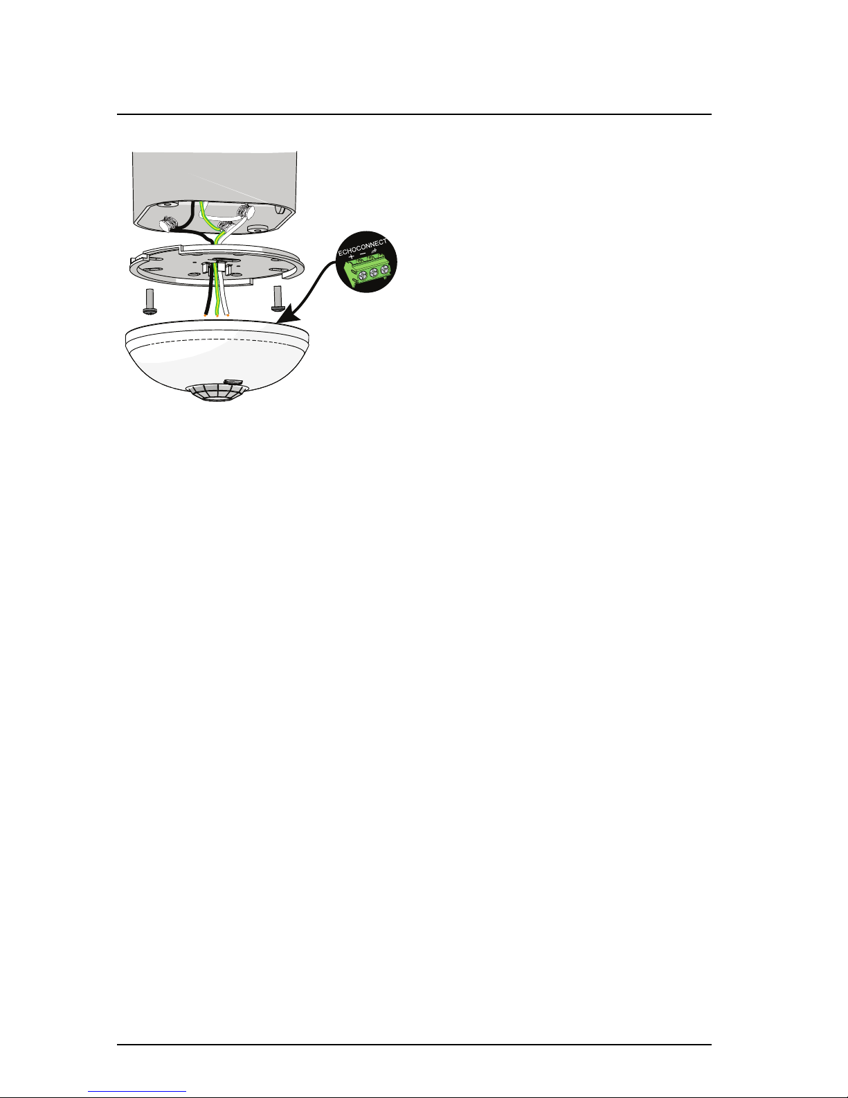
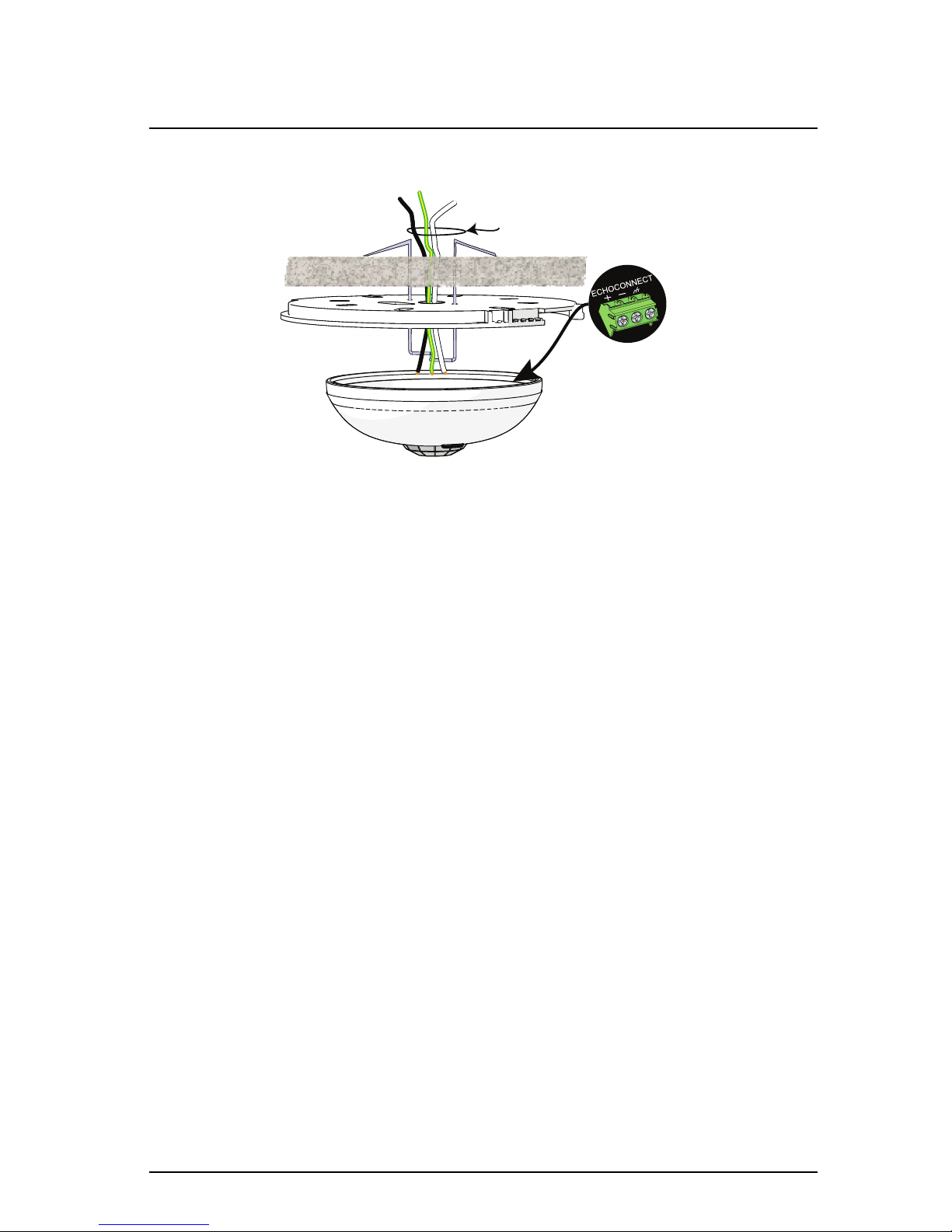
3. Orient the smooth side of the mounting plate to the junction box and
pull the EchoConnect wires (or terminated pigtail) from the junction
box through the provided holes near the center of the mounting plate.
4. Secure the mounting plate to the junction box using the screws
provided (both short and long screws are provided for convenience).
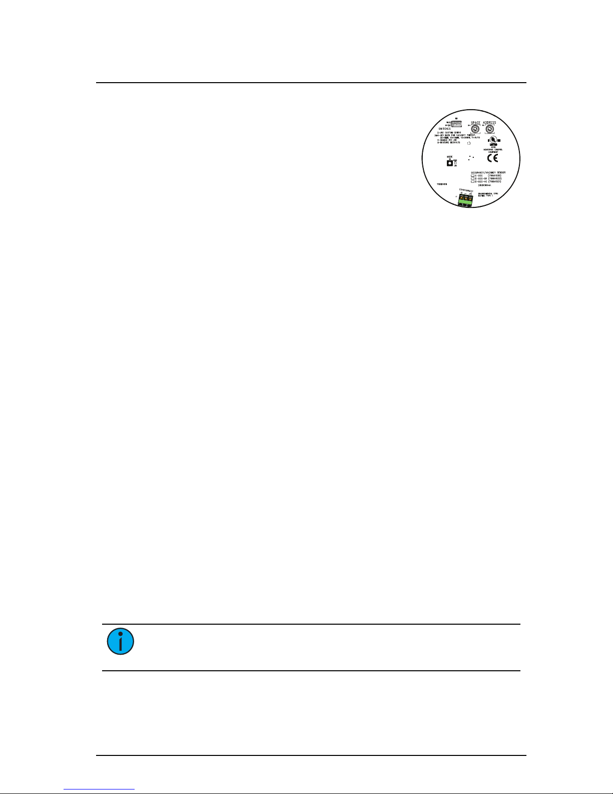
5. Strip each wire 5/16” (8 mm) and terminate the EchoConnect (white
and black wires) and the ground wire (green/yellow) to the
EchoConnect terminal block located on the sensor controller. Torque
each termination to 3.1-3.5 in-lb.
a. Terminate the white incoming wire to the data + terminal.
b. Terminate the black incoming wire to the data - terminal.
c. Terminate the green/yellow (ground) wire to the ground terminal.
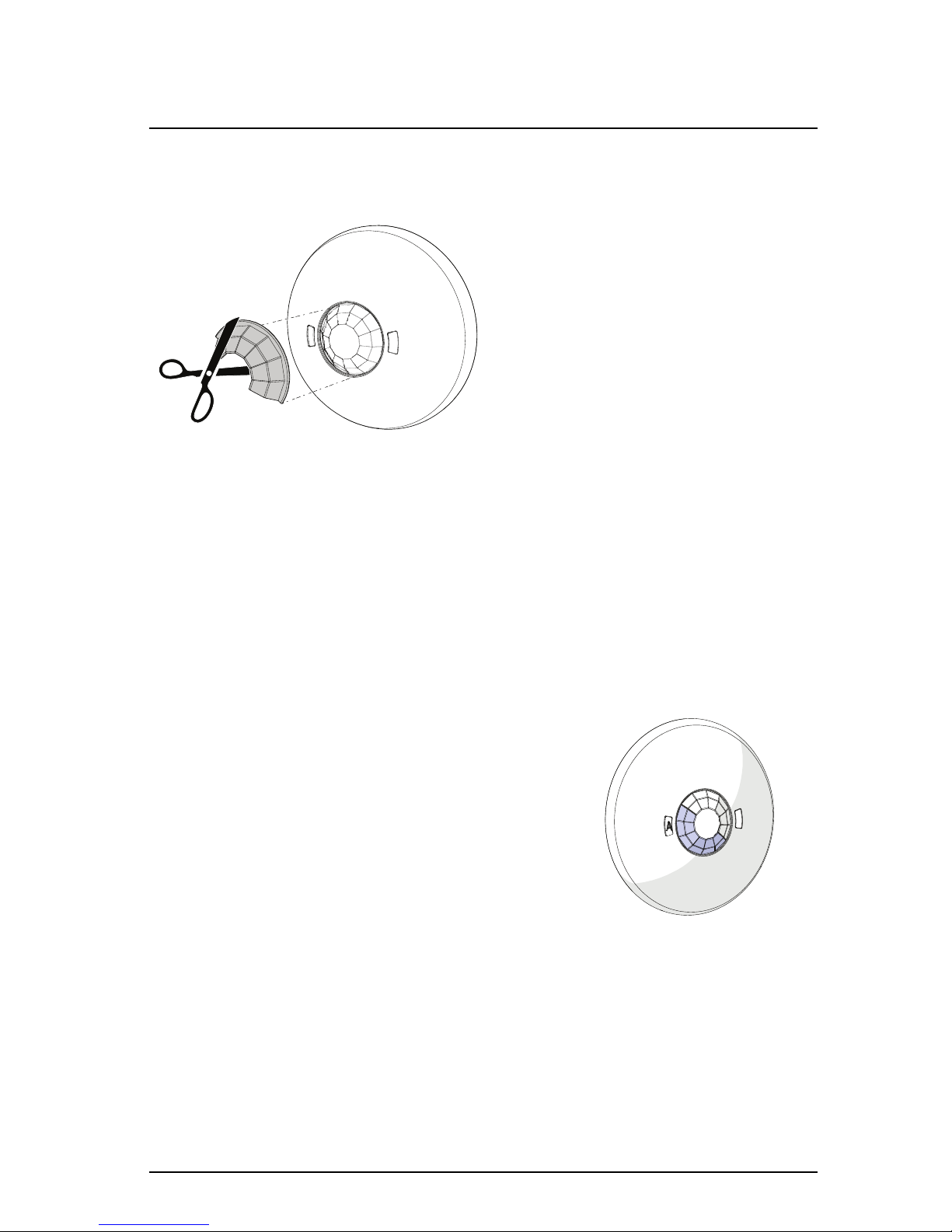
6. Attach the sensor to the mounting plate by aligning the tabs on the
sensor with the slots on the mounting plate, then twist clockwise until
the two are secured into place.
Elaho Vacancy Sensor Page 4 of 12 Echoflex Solutions, Inc.

Echoflex Installation Guide
Elaho Vacancy Sensor
Soft Ceiling Tile Installation
Poke the adapter through the ceiling tile, then bend
it over for a secure fit.
EchoConnect pigtail
and connectors
(optional use)
Terminate
wires here
1. Pull the Belden 8471 (or equivalent) and 14 AWG (2.5 mm2) ground
wire to the installation location.
2. If you are installing the sensor in series with other sensors or
stations (continuing the data run), use the provided EchoConnect
pigtail, ESD ground pigtail and connectors (not provided) to make the
terminations. Termination connectors are not provided. If you are not
continuing the data run, proceed
to Step 3.
a. Strip each wire to the appropriate length, depending on the
wire nut or other termination used.
b. Twist the data - (typically black) EchoConnect wire, the black
lead from the EchoConnect pigtail, and any continuing
EchoConnect (typically black) wire together and secure with the
wire nut.
c. Repeat the above steps for the data + (typically white)
EchoConnect wire, and for the ESD ground wires.
3. Create a hole for wire pass-through in the ceiling tile by poking
through the center hole or oblong hole of the mounting plate, then pull
the wires through.
4. Orient the smooth side of the mounting plate to the finished side of
the ceiling tile and align and insert the soft ceiling tile adapter through
the holes provided near the center of the mounting plate. Reference
the graphic above.
5. Poke the tines of the adapter through the ceiling tile, then bend each
tine over in opposite directions for a secure fit on the unfinished side
of the ceiling tile.
Elaho Vacancy Sensor Page 5 of 12 Echoflex Solutions, Inc.

Echoflex Installation Guide
Elaho Vacancy Sensor
6. Strip each wire 5/16” (8 mm) and terminate the EchoConnect (white
and black wires) and ground wire (green/yellow) to the EchoConnect
terminal block located on the sensor control board. Torque each
termination to 3.1-3.5 in-lb.
a. Terminate the white incoming wire to the data + terminal.
b. Terminate the black incoming wire to the data - terminal.
c. Terminate the green/yellow (ground) wire to the labeled ground
terminal.
Sensor Configuration
The Vacancy Sensor participates in an Elaho system using the configured
Space and Address, which are selectable using the rotary switches on the rear
panel of the sensor.
Additional DIP switches and the [Mode] button, also located on the rear
panel, set the sensor functionality and the occupancy detected action.
Set Space and Address
Two rotary switches on the rear panel of the controller provide for assignment
of the sensor Space and Address. By default, these switches are set to
Space
1,
Address
1. Commands are shared by all devices within a given space.
1. Set the
Space
rotary switch to the desired number (1 through 16) for
the space you want the sensor to control.
2. Set the
Address
rotary switch to desired address (1 through 16) for the
sensor identification in the selected space.
Note: Do not duplicate a device Address within the same Space.
Elaho Vacancy Sensor Page 6 of 12 Echoflex Solutions, Inc.

Echoflex Installation Guide
Elaho Vacancy Sensor
DIP Switch Settings
DIP switches on the rear panel of the Vacancy Sensor
provide for additional configuration options including
Use Custom Config, Vacancy Timeout, Enable/Disable
PIR detection LED, and the ability to restore the sensor
to its factory defaults.
DIP Switch 2
DIP switch 2 enables “Custom Config” which
instructs the sensor to use settings that are configured using the ElahoAccess
Mobile App. This setting is Off by default.
•
When “Custom Config” is set to Off, the default position, local DIP
switch settings for Vacancy Timeout and Enable PIR LED are used.
Sensor actions can be adjusted using the program [Mode] button.
•
When “Custom Config” is set to On, all other local DIP switch settings
are ignored. Instead, the settings made by the ElahoAccess Mobile
App for Vacancy Timeout and Enable PIR LED are used.
DIP Switch 3&4
DIP switch 3 & 4 set the “Vacancy Timeout” to 5, 15, 30 minutes, or Auto.
See
Vacancy Timeout on the next page
.
•
5 min = Switches 3 and 4 are Off.
•
15 min = Switch 3 is Off and Switch 4 is On (default).
•
30 = Switch 3 is On and Switch 4 is Off.
•
Auto = Both switches are On. See
Auto Vacancy Timeout on the next
page
.
DIP Switch 5
DIP switch 5 enables/disables the red PIR detection LED. When the switch is
Off, the PIR LED disables unless it is in Walk Test mode. When set to On, the
red PIR LED will illuminate the sensor lens when movement is detected. The
default position is On.
DIP Switch 8
DIP switch 8 provides a “Restore Defaults at Boot” function. The factory
defaults are restored by setting this DIP switch On, and cycling power to the
station. The default position is Off.
Note: DIP switches 1, 6, and 7 are not currently used and are reserved
for future development. Leave them at their default Off setting.
Elaho Vacancy Sensor Page 7 of 12 Echoflex Solutions, Inc.

Echoflex Installation Guide
Elaho Vacancy Sensor
Power Up and Test
Power Up
All EchoConnect terminations in the system must be made before applying
power to the system and sensor. When the sensor is powered up, the PIR LED
illuminates for one minute for calibration and warm-up, and then returns to
normal operation.
Configuration
Basic Configuration Mode
When the Vacancy Sensor is in Basic config mode (DIP switch 2 set to Off), the
sensor will activate a Space Off command when vacancy is detected.
Custom Configuration Mode
When functionality other than Space Off is required, place the sensor in
Custom config mode (DIP switch 2 On). Customization of the Vacancy Sensor
and all actions are configured using the ElahoAccess Mobile App.
For more detailed information about custom configuration options available
for the Vacancy Sensor using ElahoAccess, reference the ElahoAccess Mobile
App integrated help system.
Vacancy Timeout
Vacancy timeout is the amount of time the sensor waits to take action after
no movement is detected. By default, vacancy timeout is set to 15 minutes
(indicated by DIP switch 3 set to Off and 4 set to On). When the vacancy
timeout ends, the grace period begins.
When the sensor detects vacancy, the vacancy timeout period begins. If the
sensor does not detect occupancy again during the vacancy timeout period,
the lights turn off and a 30 second grace period begins.
Grace Period
The sensor features a 30 second grace period after a vacancy timeout occurs
to help prevent false vacancy detection. During this grace period, if the sensor
detects occupancy, it will restore the previous lighting condition.
Auto Vacancy Timeout
The “Auto” vacancy timeout setting varies vacancy the timeout between
5 and 30 minutes depending on how often it identifies an occupancy trigger
after a vacancy timeout occurs (during the grace period).
Elaho Vacancy Sensor Page 8 of 12 Echoflex Solutions, Inc.

Echoflex Installation Guide
Elaho Vacancy Sensor
Lens Masking
Lens masks are provided in the packaging for your convenience, used to block
a section of the lens from detecting vacancy.
1. As needed, trim the lens mask to
fit the desired area to be blocked.
2. Gently press down on the sensor
lens, which will give only slightly,
and insert the lens mask.
3. Rotate the lens mask around the
dome to block the required area
from sensing.
PIR Detection
The PIR detection automatically adjusts its sensitivity to eliminate nuisance
tripping. When the sensor powers on, the red PIR LED illuminates for
approximately 60 seconds to identify “Power Up” state. Sensor configuration
is not allowed. During this time, no events are triggered.
Test
Vacancy Sensors offer a Walk Test mode which shortens the vacancy timer to
ten seconds, allowing for simple and quick verification of the sensors
coverage and range in the installed space.
Auxiliary
button
Walk Test
button
Walk Test mode automatically exits and the
sensor returns to normal operation after five
minutes and can be manually terminated early
by pressing the [Walk Test] button.
Elaho Vacancy Sensor Page 9 of 12 Echoflex Solutions, Inc.

Echoflex Installation Guide
Elaho Vacancy Sensor
Enable Walk Test Mode
1. Prepare the site for configuration.
a. Make certain the sensor and lighting loads are powered and
connected for control by the Elaho controller.
b. You will need direct access to the Vacancy Sensor in order to
place it into Walk Test mode.
2. Press the [Walk Test] button on the front of the sensor to enable the
Walk Test feature at the sensor. A green LED will begin to flash,
indicating Walk Test is enabled and the vacancy/no vacancy occupancy
timer will be shortened to ten seconds.
3. Move throughout the space including corners and areas that may
specifically be obscured from line of sight to the sensor. Each time the
sensor detects movement, the lens will illuminate red.
4. Adjust the lens masking, if installed, blocking certain areas of the
installed space from sensor detection. See
Lens Masking on the
previous page
.
5. Walk Test mode will automatically exit after five minutes from the
time it was enabled. To manually exit the Walk Test mode, press
either of the buttons on the sensor.
Elaho Vacancy Sensor Page 10 of 12 Echoflex Solutions, Inc.

Echoflex Installation Guide
Elaho Vacancy Sensor
High Ceiling side view
0
3.0m
10ft
3.0m
10ft
6.1m
20ft
6.1m
20ft
9.1m
30ft
9.1m
30ft
12.2m
40ft
12.2m
40ft
0
12.2m
40ft
9.1m
30ft
6.1m
20ft
Small Room side view
0
0
1.5m
5ft
1.5m
5ft
3.0m
10ft
3.0m
10ft
4.6m
15ft
4.6m
15ft
6.1m
20ft
6.1m
20ft
8ft
2.4m
10ft
3.0m
12ft
3.7m
Large Room side view
0
8ft
2.4m
10ft
3.0m
12ft
3.7m
0
3.0m
10ft
3.0m
10ft
6.1m
20ft
6.1m
20ft
9.1m
30ft
9.1m
30ft
12.2m
40ft
12.2m
40ft
Elaho Vacancy Sensor Page 11 of 12 Echoflex Solutions, Inc.

Echoflex Installation Guide
Elaho Vacancy Sensor
Elaho Vacancy Sensor Page 12 of 12 Echoflex Solutions, Inc.
This manual suits for next models
2
Table of contents
Other echoflex Security Sensor manuals