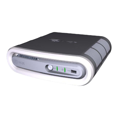
ECKELMANN AL 300 W User manual

Version 3-1 05. Dezember 2019
Operating instruction
AL 300 W / AL 300 S
The operation terminal in the E*LDS system - Version V5.08
AL 300 S
AL 300 W

Version 3-1 05. Dezember 2019
Eckelmann Gruppe
Eckelmann AG
Business Unit Refrigeration and Building Management Systems
Berliner Straße 161
65205 Wiesbaden, Germany
Telephone +49 611 7103-0
Fax +49 611 7103-133
www.eckelmann.de
Board of Directors:
Dr.-Ing. Gerd Eckelmann, Vorsitzender, Dr.-Ing. Peter Cordes, Dr.-Ing. Frank-Thomas Mellert
Deputy Board Member:
Dipl.-Ing. Peter Frankenbach, Dr.-Ing. Marco Münchhof, Dr.-Ing. Frank Uhlemann
Chairman of the supervisory board:
Hubertus G. Krossa
Registration court / registration number
District court Wiesbaden, Germany
HRB 12636
Before commissioning and use, please check that this is the latest version of the document.
With the publication of a new version of the documentation, all previous versions lose their validity.
Errors and technical modifications are expressly reserved.
Information on safety and connection instructions
are described in detail in chapter 1 ”Industrial safety notes”.
All rights to any use whatever, utilisation, further development, forwarding and creation of copies remain with
the Eckelmann AG company.
In particular, neither the contract partners of Eckelmann AG nor other users have the right to distribute or mar
ket the IT programs/program parts or modified or edited versions without express written permission. To some
extent, names of products/goods or designations are protected for the respective manufacturer (registered
trademarks etc.); in any case, no guarantee is assumed for their free availability/permission to use them. The
information provided in the description is given independently of any existing patent protection or other third-
party rights.

i
Version 3-1 05. Dezember 2019
Notice:
Conventions 1.....................................................................
Explanation of 'General Instructions' 1.................................................
Explanation of 'Safety Instructions and Hazard Warnings' 1..............................
Warning Signs and Symbols Employed 2..............................................
1 Safety instructions 3.....................................................
1.1 Disclaimer in the event of non-compliance 4.................................
1.2 Personnel requirements, requirements on staff 4.............................
1.3 Intended use 5...........................................................
1.4 BGV A3 - Five safety rules 5...............................................
1.5 Electrostatic sensitive devices (ESDs) 6.....................................
1.5.1 ESD - Rules for handling and working 6.....................................
1.6 Abbreviations used 6......................................................
2 Application of AL 300 7..................................................
2.1 Applications 8............................................................
2.2 Circuit points 9...........................................................
2.3 Compatibility with other LDS components 9..................................
2.3.1 New features compared to earlier versions 10.................................
3 Function of AL 300 11.....................................................
3.1 Messages and alarms 11...................................................
3.1.1 Resetting alarms 12........................................................
3.2 Digital inputs 12...........................................................
3.2.1 Alarm and signal inputs 13..................................................
3.3 Relay outputs 13..........................................................
3.3.1 Alarm relays PRIO1 / PRIO2 13.............................................
3.3.2 Horn relay 15/16/18 13.....................................................
3.4 CAN bus station monitoring 14..............................................
3.5 Alarm suppression in manual shutdown of case controllers 15...................
4 Installation and Startup of AL 300 17.......................................
4.1 Panel mounting of AL 300 S 17..............................................
4.2 Wall mounting of AL 300 W 18..............................................
4.3 Setting the CAN bus address 18.............................................
4.4 Restart - restart of the controller 19..........................................

ii Version 3-1 05. Dezember 2019
4.5 First start - load factory settings 19...........................................
4.6 Special functions for startup 19..............................................
4.7 Replacing the battery 20....................................................
4.8 Firmware update using replacement of the EPROM 22.........................
5 Pin and Terminal Assignments of AL 300 23................................
5.1 Pin and terminal diagram 23................................................
5.1.1 Terminal assignment for 230 V AC power supply 24............................
5.1.2 Terminal assignment for 230 V AC relay outputs 24............................
5.1.3 Terminal assignment for 230 V AC digital inputs 24............................
5.1.4 Terminal assignment for CAN bus 25.........................................
5.1.5 Terminal assignment for the interface 25.....................................
6 Operation of AL 300 27....................................................
6.1 Operating interface 27......................................................
6.2 Menus and screens 27.....................................................
6.2.1 Deactivate entry block 30...................................................
6.2.2 Superuser mode (granting Superuser rights) 31...............................
6.3 Remote operation/parameter setting of a E*LDS component 32.................
7 Menu structure of AL 300 33...............................................
7.1 Main menu AL 300 33......................................................
7.1.1 Menu 0 Main menu 34.....................................................
7.1.2 Menu 1 Alarms 35.........................................................
7.1.3 Menu 2 Overview 36.......................................................
7.1.4 Menu 3 Archive 36.........................................................
7.1.5 Menu 4 Messages (Event Log) 36...........................................
7.1.6 Menu 5 Remote Control 37.................................................
7.1.7 Menu 6 Store Computer 37.................................................
7.1.8 Menu 7 Monitoring 38......................................................
7.1.9 Menu 8 Monitor 42.........................................................
7.1.10 Menu 9 Parameters 42.....................................................
7.1.11 Menu 0 BMS Overview 44..................................................
8 Decommissioning and disposal 45.........................................
8.1 Decommissioning / Demounting 45..........................................
8.2 Disposal 45...............................................................
9 Alarms and Messages of AL 300 47........................................
10 Specifications of AL 300 49...............................................
10.1 Electrical data 49..........................................................

iii
Version 3-1 05. Dezember 2019
10.2 Mechanical data 51........................................................
10.2.1 Panelmounting of AL 300 51................................................
10.2.2 Mounting frame for panel mounting AL 300 S 52...............................
10.2.3 AL 300 W for wall mounting 53..............................................
11 Order numbers and accessories of AL 300 55..............................
11.1 Operator Terminal AL 300 55...............................................
11.2 Accessories for Operator Terminal 55........................................

1
Version 3-1 05. Dezember 2019
Conventions
Explanation of 'General Instructions'
A general instruction is composed of two elements:
1. A pictogram of a hand at the side of the page as well as
2. The actual text:
For example:
Further information on the device's degree of protection is contained in the chapter ”Technical Data”.
Explanation of 'Safety Instructions and Hazard Warnings'
Safety instructions or hazard warnings are composed of four elements:
1. The pictogram (warning sign / symbol) at the edge of the page.
2. A short, concise description of the danger.
3. A description of the possible consequences.
4. A catalogue with prevention measures.
For example:
Warning - hazardous electrical voltage!
Danger of electric shock! BEFORE and AFTER connection it
must checked that the 230 V AC relay outputs are off load!
On the following pages the warning signs and symbols employed for
the safety instructions and hazard warnings in this documentation are described in more detail.

2Version 3-1 05. Dezember 2019
Warning Signs and Symbols Employed
Explanation of the warning signs and symbols employed for the safety instructions and hazard warnings in this
documentation:
SAttention symbol - general hazard warning
1. Hazard warning
The attention symbol indicates all safety instructions in this operating instruction and service manual,
which, if not observed, could result in danger to life and limb. Carefully comply with the work safety in
structions and proceed with special caution in these cases.
2. Attention
The attention symbol highlights guidelines and regulations, instructions and correct working procedures
that must be carefully observed in order to prevent damage to or destruction of LDS components or a
malfunctioning (for example to avoid damage to goods).
Failure to observe the attention symbol can result in personal injury (in extreme cases serious injuries or
death) and/or material damage!
SVoltage symbol - warns of hazardous electrical voltage
This work safety symbol warns of danger from a hazardous electrical voltage,
with potential consequences such as serious injury or death.
SESD symbol - warns of electrostatic sensitive components and assemblies
This symbol indicates electrostatic sensitive components and assemblies,
for details see chapter 1.5.
SNote symbol
The note symbol highlights practice tips and other useful information contained in this
operating instruction and service manual.
SBattery disposal symbol
Never dispose of this product with other household waste. Please inform yourself of the local regula
tions for the separate disposal of electrical and electronic products. The correct disposal of your old
equipment will protect people and the environment from possible negative effects.
You will find further information in the chapter ”Decommissioning and Disposal”.

Safety instructions
3
Version 3-1 05. Dezember 2019
1 Safety instructions
The safety regulations, codes and notes contained in this section must definitely be observed and
complied with at all times. During repairs on the entire LDS system, the accident prevention regula
tions and general safety instructions must be observed. Important information (safety instructions
and hazard warnings) are indicated by corresponding symbols (see page 1 of the chapter ”Conven
tions”).
Follow these instructions in order to prevent accidents and danger to life and limb, as well as dam
age to the LDS system.
Warning - hazardous electrical voltage!
Danger of electric shock! Beware of external voltage at the digital inputs and outputs!
All device connections/plugs are only to be plugged in, unplugged and/or wired when off load.
SThis operating instruction is an integral part of the equipment. It must be kept in the proximity of the equip
ment and must be stored for future use, so that it can be referred to when necessary. To avoid operating er
rors, the operation instructions must always be kept available for operating and maintenance staff, see Chap
ter 1.2.
SFor safety reasons, the equipment must not be used for any application other than described in the operating
instruction i.e. only for the intended use, see Chapter 1.3.
SBefore using the equipment, always check that its limits are suitable for the intended application.
SCheck that the electric power supply is correct for the equipment before connecting it to power.
SWhen using un-coded plug connectors it is possible to connect them so that there is a danger to life and limb!
If this cannot be excluded, coded plug connectors must be used.
SSpecified ambient conditions (e.g. humidity and temperature limits) must be observed and complied with in
order to avoid malfunctioning (see Section “Specifications”).
SCheck correct wiring of the connections before switching on power to the equipment.
SNever operate the equipment without its casing. Before opening the casing the equipment must be switched to
zero potential.
SNote and observe maximum load on relay contacts (see Section “Specifications”).
SContact the supplier in any malfunction.
1. According to experience, error message transmission is not yet fully functional during commis
sioning (no telephone line laid etc.). In such cases, it is strongly recommended to use the available
PRIO1/PRIO2 alarm contacts at the operator terminal to realise the transmission of alarms via a
telephone network.
2. Following the setup of error message transmission, i.e. alarm signalling, it must be tested and in
spected to ensure correct functioning.
For further information on the CAN bus, see the operating instruction
”Basic and General Safety and Connection Instructions”.

Safety instructions
4Version 3-1 05. Dezember 2019
Work on electrical equipment may only be undertaken by authorized and duly trained personnel
(as defined by DIN/VDE 0105 and IEC364) with full observance of the currently valid regulations
contained in the following:
- VDE Regulations
- Local safety codes
- Intended use see chapter 1.3
- BGV A3 - Five Safety Rules see chapter 1.4
- ESD precautions and rules see chapter 1.5.
- Operating instructions
1.1 Disclaimer in the event of non-compliance
These operating instructions contain information on the commissioning, function, operation and maintenance of
the controls and of the associated components.
Observance of these operating instructions is a prerequisite for safe and trouble-free operation.
1.2 Personnel requirements, requirements on staff
Special skills are required for project planning, programming, assembly, commissioning and maintenance work.
This work may be performed by qualified and specially trained staff.
The staff involved in installation, commissioning and maintenance must have received the special training
needed for them to work on the unit and on the automation system.
The project planning and programming staff must be familiar with the safety concepts involved in automation
technology.
Expertise is a requirement for any work on electrical systems. Work on electrical installations may only be per
formed by trained electrical specialists (or may only be performed when directed or supervised by them). The
applicable regulations (e.g. DIN EN 60204, EN 50178, BGV A2, and DIN VDE 0100/0113) must be followed.
The operating staff who deal with the unit/machine and the controls must be correspondingly trained and familiar
with the operating instructions.

Safety instructions
5
Version 3-1 05. Dezember 2019
1.3 Intended use
This control system may only be used for the purpose for which it is intended:
The AL 300 control system has been designed for use as operator terminal in commercial, industrial refrigera-
tion systems and building management systems with the intended functional scope as described in these oper
ating instructions, and it is to be used under the environmental conditions in these instructions.
Follow the safety instructions, as well as the instructions on installation, commissioning, operation and mainte
nance. Only THEN should you start commissioning or operating the machine/system.
The safety and function of the machine/unit is only assured in the use for which it has been intended.
Never use the machine/unit, its components, assemblies or parts of it for a different purpose.
The installation may be only operated for the first time when the entire unit has been shown to conform
to the EC Directives.
1.4 BGV A3 - Five safety rules
The following rules must be strictly observed:
1. Disconnect electric power: Disconnect power at all connections of the entire installation on which
work is to be carried out.
Warning - hazardous electrical voltage!
Beware of possible external power supplies! BEFORE and AFTER connection it must be checked
that the controller is off load! All device connections/plugs are only to be plugged in, unplugged and/
or wired when off load.
2. Secure against reconnection of power: Tag the disconnected equipment with the following information:
‐ What has been disconnected from power
‐ Why it has been disconnected
‐ Name of person who disconnected power
‐ Use a suitable lock-out (e.g. padlock) to prevent reconnection of power.
3. Make sure that power is off (authorized and duly trained personnel only):
‐ Check with voltmeter immediately before use.
‐ Check that power is off on all connections at the disconnection point.
‐ Check that power is off on all connections at the place of work.
4. Ground and short circuit: Ground and then short circuit all electrical parts at the place of work.
5. Cover or bar off adjacent power-carrying parts: Any equipment carrying power adjacent to the work area
must be covered by suitable means (e.g. insulating cloths or panels).

Safety instructions
6Version 3-1 05. Dezember 2019
1.5 Electrostatic sensitive devices (ESDs)
Electronic components and assemblies (e.g. printed circuit boards) are vulnerable to electrostatic
discharge. Regulations for handling and working with electrostatic sensitive devices must definitely
be observed and complied with, see also section 1.5.1!
All electrostatic sensitive devices (ESDs) are identified by the warning sign illustrated. Electrostatic discharge is
caused by friction of insulating materials (e.g. floor coverings, synthetic fiber clothing, etc.).
Even slight charges can cause components to be damaged or destroyed. Damage cannot always be ascer
tained directly and it may take time for the component to actually fail in operation.
1.5.1 ESD - Rules for handling and working
Transport and store ESDs only in the protective packaging provided.
Avoid materials that may produce electrostatic discharge, for example
‐ Plastic containers and table tops
‐ Synthetic fiber clothing
‐ Plastic-soled shoes
‐ Plastic file covers
‐ Styrofoam packaging
‐ Computer monitors, etc.
Preferably wear the following:
‐ Cotton work clothes
‐ ESD shoes with conductive soles or leather soles
Use the following:
‐ Conductive flooring
‐ ESD workstations equipped with suitable tools (grounded soldering guns, antistatic wrist straps, etc.)
‐ Conductive ESD bags, conductive plastic containers, IC tubes or cartons lined with conductive foam
‐ Containers and worktops made of wood, metal or conductive plastics or paper bags
1.6 Abbreviations used
DIN Deutsches Institut für Normung e. V.
EGB Elektrostatisch Gefährdete Bauelemente oder Baugruppen
ESD Electro-static discharge (Electro Sensitive Devices)
VDE Verband der Elektrotechnik Elektronik Informationstechnik e.V.
IEC International Electric Committee
BGV A3 Employer’s Liability Association regulations for health and safety in the workplace

Application of AL 300
7
Version 3-1 05. Dezember 2019
2 Application of AL 300
AL 300 S
AL 300 W
The AL 300 Operator Terminal can be used in an E*LDS system with a CI 4x00 System Centre or a CI 3000
Store Computer (A). However, in contrast to the system centre or store computer, it does not have a modem
interface, no archive storage and no connection for SIOX extension modules. Joint operation of up to 9 AL 300
Operator Terminals is possible within an E*LDS system.
Other possible uses can occur for the modernisation of old systems if type VS 1000 / VS 2000 pack controllers
are removed and replaced for example with a VS 3010 where an operator terminal (B) is required for its
(remote) operation, parametrisation and alarm signalling.
There are 2 mounting-specific versions of the operator terminal available:
AL 300 S: For installation in the control panel; the mechanical dimensions are identical to the
dimensions of the CI 4x00 System Centre / CI 3000 Store Computer
AL 300 W: For wall mounting in a plastic casing

Application of AL 300
8Version 3-1 05. Dezember 2019
2.1 Applications
E*LDS components
Functions With
CI 4x00
With
CI 3000 /
CI 3I00
With for
example
VS 3010
Centralized parameter setting and configuration of all LDS
components via CAN bus. The AL 300 can be used for remote con
trol and configuring of all LDS components from a single location
via CAN bus.
Exceptions: LAN Gateway, Combi Gateway, CI 4x00
FFF
In-use change of the user language can also be made from the
central location.
FFF
Monitoring of two connected external digital signals
(external alarms)
FFF
Alarm signalling by indicator light and buzzer and by external horn
and two alarm contacts.
FFF
Central display of alarms of all E*LDS components FFF
Central display of messages of all E*LDS components -F F
Centralized display of operating data generated by all E*LDS
components.
-F F
Only if no CI 4x00 System Centre or a
CI 3000 Store Computer is available or has failed
Monitoring of CAN bus and operational status of all E*LDS
components. Alarm is generated in fault or failure of CAN bus and
failure of components.
FFF
The AL 300 Operator Terminal has a real-time clock with power
reserve for central time synchronisation. The clock supports the
automatic changeover between summer and winter time.
The date and time of all E*LDS components can be adjusted sys
tem-wide via the CAN bus using the AL 300 Operator Terminal or
their internal clocks are synchronised cyclically.
This is not possible in systems with a CI 4x00 System Centre.
-F F

Application of AL 300
9
Version 3-1 05. Dezember 2019
2.2 Circuit points
Connectivity for the AL 300 Operator Terminal is as follows (for details see chapter Pin and Terminal Assign
ments):
Inputs/outputs:
S2 x digital inputs 230 V AC e.g. for monitoring of external alarms
S3 x relay outputs 230 V AC, floating output:
- 2 x alarm contacts (PRIO1/2) e.g. for connection of a telephone dialling device
- 1 x audible signalling unit (HORN)
S1 front button with external wiring option
Interfaces:
SCAN bus interface for interconnection of all LDS components (CI 4x00 System Centre, CI 3000 Store
Computer, other AL 300 Operator Terminal types, UA 300-/UA 400 Family case/coldroom controllers and
VS 3010, VS 3010 BS, VS 3010 CT, Vs 3010 WP, FS 3010 or VS 300 Pack Controllers, Receiver Modules
WR 300 / WR 400)
SRS232 port for special functions (no function, no connection to LDSWin is possible)
2.3 Compatibility with other LDS components
Version 5.06
Functional adaptation to the CI 4x00 System Centre with Version 6.0.0 or higher
Version 4.10
When a CI 3000 Store Computer of Version 4.24 or higher is connected to the LDS System, the AL 300 Opera
tor Terminals used must also be Version 4.10 or higher.
Version 4.08
When a CI 3000 Store Computer of Version 4.19 or higher is connected to the LDS System, the AL 300 Opera
tor Terminals used must also be Version 4.08 or higher.

Application of AL 300
10 Version 3-1 05. Dezember 2019
Version 4.06
When a CI 3000 Store Computer of Version 4.08 or higher is connected to the LDS System, the AL 300 Opera
tor Terminals used must also be Version 4.06 or higher.
Version 4.03
When a CI 3000 Store Computer of Version 4.03 or higher is connected to the LDS System, the AL 300 Opera
tor Terminals used must also be Version 4.03 or higher.
Version 3.04
Version 3.04 of the AL 300 Operator Terminal is fully compatible with all LDS components.
2.3.1 New features compared to earlier versions
Version 5.06
If a CI 4x00 System Centre with Version 6.0.0 or higher or a CI 3000 Store Computer with Version 5.00 or hig
her is available in the E*LDS system, AL 300 Operator Terminals with Version 5.06 or higher must also be
used. LDSWin with Version 2.4.4008 or higher is required for systems with a CI 4x00 System Centre with Ver
sion 6.0.0 or higher.
Version 4.10
Functionally adaptation to CI 3000 Store Computer version 4.24 or higher.
Version 4.08
Functionally adaptation to CI 3000 Store Computer version 4.19 or higher.
(u.a. Integration of the WR 300 / WR 400 receiver modules for TS 30 W wireless sensors)
Version 4.06
Functionally adaptation to CI 3000 Store Computer version 4.03 or higher
(e.g. integration of compact controllers UA 30Rx/Dixell/other controllers)
Version 4.03
Functionally adaptation to CI 3000 Store Computer version 4.03 or higher.
Version 3.04
SSupports service mode of CI 3000 Store Computer:
Service technician can suppress remote alarming for a defined time (1 to 255 min.) while maintenance is be
ing carried out.
SAlarm takeover by service center
SLast-in alarm changed on alarm relays:
New alarms are now reported during the time delay.

Function of AL 300
11
Version 3-1 05. Dezember 2019
3 Function of AL 300
3.1 Messages and alarms
Use in the E*LDS system
The AL 300 Operator Terminal, in addition to the CI 4x00 System Centre and the CI 3000 / CI 3100 Store Com
puter, is the central collection point for messages of all E*LDS components that are listed in an alarm list and
displayed to the operator - see menu 1 "Alarms". The alarm log can store 100 entries. When it is full, the next
new message overwrites the oldest entry. Detailed information on the alarm and message texts is provided in
chapter 8 Alarms and Messages.
Messages generated by the E*LDS components are transmitted to the AL 300 Operator Terminal(s) via the
CAN bus with one of the following priorities:
-- No message is generated, no alerting
0, 10, 20,...90 Message - only entry in the message list
1, 11, 21,...91 High priority alarm - entry in the alarm and message list, activation of the alarm relay PRIO1
(e.g. in the event of potential damage to goods)
2, 12, 22,...92 High priority alarm - entry in the alarm and message list, activation of the alarm relay PRIO2
(e.g. in the event of faults which can be rectified by customer services on the following day)
3, 13, 23,...93 Low priority alarm - Alarm entry in the message and alarm list
4, 14, 24,...94
5, 15, 25,…95
6, 16, 26,…96
7, 17, 27,…97
8, 18, 28,...98
9, 19, 29,...99 Low priority alarm - Only for local alarm signal, no modem,
can be configured to operate the AUX relay
Messages of Priority 0 are ignored by the AL 300 and are not displayed. Exception: Messages gen
erated by the AL 300 Operator Terminal itself!If available in the E*LDS system, the display is only
made in the message list of the system centre / store computer. Messages with the priorities X1 and
X2 are designated with "Alarm" below.
Alarms shown in the alarm log can be cancelled and deleted. Each new alarm logged in the alarm log sounds
the audible alarm devices (internal buzzer or external horn). These can be cancelled by pressing the ALARM
RESET key:
PRIO 1
PRIO 2
ALARM
RESET
ZNR: 51203 67 530

Function of AL 300
12 Version 3-1 05. Dezember 2019
Danger of failure of alarm messaging! Successful transmission of alarms from E*LDS components
cannot be assured in systems where CAN bus communication is severely disturbed (frequent messages
of CAN faults or actual CAN failure).
In order to ensure the correct functioning of individual alarm paths (e.g. via modem and relay contacts),
they must be checked by triggering test alarms on a cyclical basis, see the chapter Operation.
As a rule, it must be ensured that the alarms are sent via a number of independent alarm paths.
The following messages and alarms can be generated by the AL 300 Operator Terminal:
SAlarms
- Hardware error
- CAN bus failure/fault
- AL 300 first start
- AL 300 restart
- E*LDS component failure
- External alarms
SMessages
- Changed configuration or date/time
3.1.1 Resetting alarms
Alarms can be reset by pressing the ALARM RESET key while the alarm log (Menu 4 - Message and Alarm
Log) is displayed. Reset is effective throughout the system, meaning that all alarms that can be reset are in fact
reset in all components.
Alarms can only be reset when reported as corrected. Reset alarms are hidden in the alarm log.
For subsequent troubleshooting, all previously acknowledged and thus hidden alarms can be dis
played on the operator terminal again by pressing and holding (approx. 3 seconds) the buttons
MODE + ALARM RESET. These alarms can afterwards be reset and hidden in the normal manner.
3.2 Digital inputs
The operator terminal has 2 digital 230 V AC inputs (AL.1: A1/A2 and AL.2: B1/B2).
These can be configured for monitoring and alarm signalling of external maintenance groups (external alarms).
Warning - hazardous electrical voltage!
Danger of electric shock! BEFORE and AFTER connection it
must checked that the 230 V AC relay outputs are off load!

Function of AL 300
13
Version 3-1 05. Dezember 2019
3.2.1 Alarm and signal inputs
The AL 300 Operator Terminal has two digital inputs 230 V AC for monitoring and alarming external systems/
alarms (terminals AL.1: A1/A2 / AL.2: B1/B2). The inputs are initially deactivated and must be configured prior
to use (Menu 7-5) for N.C. or N.O. operation, i.e. to signal alarm in absence or presence of signal power.
A user-definable message text of 19 characters can be assigned individually to each alarm input to be displayed
with the alarm.
Alarm is delayed for a definable time between 0 and 255 min. Each alarm input also has a definable alarm prior
ity between 0 and 99. Alarm inputs of priority X1 and X2 generate normal alarms that are displayed in the alarm
log and transmitted via the configured alarm routes.
3.3 Relay outputs
Warning - hazardous electrical voltage!
Danger of electric shock! BEFORE and AFTER connection it
must checked that the 230 V AC relay outputs are off load!
Low potential voltage and safety extra-low voltage may not be
connected toghether at the relais outputs 15/16/18, 25/26/28 and 35/36/38!
3.3.1 Alarm relays PRIO1 / PRIO2
The AL 300 Operator Terminal has a digital alarm output (floating relay contacts) for each alarm priority X1 and
X2, usable for example to operate a telephone dialer (terminals PRIO.1: 35/36/38 / PRIO.2: 25/26/28). When an
alarm is generated by an E*LDS component, the output assigned to the respective priority is activated.
If the output was already activated, it is deactivated for about 5 seconds and then reactivated (last-in alarm) if
previous activation of the output was 5 minutes or more past.
If two or more alarms are received during this interval, the last-in alarm is postponed until the interval has ex
pired. The alarm outputs are automatically deactivated for instance when the alarm log contains no alarm of the
respective priority after pressing the ALARM RESET key.
The alarm outputs are the latching type with time-delayed automatic alarming of power failure. The current out
put states are preserved if power supply to the controller is switched off briefly. If the controller remains off for
longer than about 5 minutes, the outputs are switched to the alarm state.
3.3.2 Horn relay 15/16/18
In addition to the prioritised alarm outputs PRIO1 / PRIO2, the controller is also equipped with a changeover
contact which can be used to connect an external audible alarm signalling unit (HORN) using the terminals
15/16/18.

Function of AL 300
14 Version 3-1 05. Dezember 2019
3.4 CAN bus station monitoring
The AL 300 Operator Terminal performs cyclic check on presence of all E*LDS components previously de
tected in the system. Failure of a component is detected by this station monitoring and reported by Computer
Fault alarm.
Every new E*LDS component connected to the CAN bus is detected via “plug and play” automatically by the
store computer and included in station monitoring (Screen 7-1).
E*LDS components CAN bus address Max. no. of E*LDS components on CAN bus
Case controller of the UA 300 and UA 400 series 1..99 99
VS 3010 / VS 3010 BS / VS 3010 CT / VS 3010 WP
FS 3010 / VS 300 / VS 3010 C pack controllers
101..109 9
CI 4x000 System Centre 111
127
1 System Centre
1 integrated LAN Gateway
CI 3000 / CI 3100 Store Computer 111 1
AL 300 Operator Terminal 112 .. 116, 117 .. 120 Max. 9 or max. 5, if 4 receiver modules are
present in the system.
Receiver module WR 300
for wireless temperature sensors TS 30 W
117 .. 120 4 (only possible, if NO operator terminal
uses these CAN bus addresses)
LDSWin PC via COM port 121 1
DDC modules of building control system (BCS) 122..125 4
Maximum of 4 if there are no Modbus TCP
master gateways installed in the system
LDSWin PC via CAN bus PC adapter 126 1
LDSWin PC via LAN gateway
(from version 1.1c or higher)
126 or 127 1
Combi-Gateway
- LAN-Gateway
- XML-Gateway
- Modbus TCP-Master 1..4 Gateway
126 or 127
110
122..125
1
1
Maximum of 4 if there are no DDC modules in
stalled in the system.
This takes over the station monitoring in systems with system centres and store computers If there
is no system centre or store computer installed in the system, the AL 300 with the respective lowest
CAN bus address cyclically checks the presence of all E*LDS components once they have been
detected in the system.

Function of AL 300
15
Version 3-1 05. Dezember 2019
3.5 Alarm suppression in manual shutdown of case controllers
Shutdown of a refrigerated case or coldroom is detected by CAN bus station monitoring as a failure (Screen 7-1).
The display of all AL 300 and - if present - of the CI 4x00 System Centre or of the CI 3000 / CI 3100 Store Computer
then shows the query whether the refrigeration point has been deliberately unloaded.
The user can then confirm shutdown within 5 minutes by pressing ENTER.
If confirmation is made within this interval, monitoring of the case or coldroom concerned will be deactivated
and accordingly it will not be reported as a failure.
Otherwise, or if the user answers no to the prompt by pressing the ESC key, the case or coldroom will as nor
mal be reported as failed. A case or coldroom that has been shut down is automatically re-included in station
monitoring when it is switched on again.
Any disconnection of refrigeration points is registered in the message list of the system centre /
store computer (if this is present)!
This manual suits for next models
1
Table of contents
