Ecler essentials eHSA4-60 User manual
v.20200629
eHSA4-60
HIGH IMPEDANCE AMPLIFIERS
High and low impedance multichannel amplifier
USER MANUAL

INDEX
1. IMPORTANT REMARK .............................................................................................................3
2. IMPORTANT SAFETY INSTRUCTIONS ...............................................................................3
3. IMPORTANT NOTE ...................................................................................................................5
4. INTRODUCTION ........................................................................................................................5
4.1 Main features.................................................................................................................................5
5. INSTALLATION..........................................................................................................................6
5.1 Placement, mounting, cooling..................................................................................................6
5.2 Mains connection .........................................................................................................................6
5.3 Input signal connections ............................................................................................................7
5.4 Power saving mode.....................................................................................................................7
5.5 Limiter circuit.................................................................................................................................8
5.6 Output connections .....................................................................................................................9
6. OPERATION AND USAGE ................................................................................................... 10
6.1 Start up......................................................................................................................................... 10
6.2 Input attenuators....................................................................................................................... 10
6.3 Indicators ..................................................................................................................................... 10
7. CLEANING................................................................................................................................ 11
8. FUNCTION DIAGRAM ........................................................................................................... 12
9. FUNCTION LIST ...................................................................................................................... 13
10. BLOCK DIAGRAM .................................................................................................................. 14
11. TECHNICAL CHARACTERISTICS....................................................................................... 15

1. IMPORTANT REMARK
The lightning flash with arrowhead symbol, within an equilateral triangle, is
intended to alert the user to the presence of uninsulated “dangerous voltage”
within the product’s enclosure that may be of sufficient magnitude to constitute
a risk of electric shock to persons.
The exclamation point within an equilateral triangle is intended to alert the user
to the presence of important operating and maintenance (servicing) instructions
in the literature accompanying the appliance.
WARNING (If applicable): The terminals marked with symbol of “ ” may be of
sufficient magnitude to constitute a risk of electric shock. The external wiring connected to
the terminals requires installation by an instructed person or the use of ready-made leads
or cords.
WARNING:To prevent fire or shock hazard, do not expose this equipment to rain or
moisture.
WARNING:An apparatus with Class I construction shall be connected to a mains socket-
outlet with a protective earthing connection.
2. IMPORTANT SAFETY INSTRUCTIONS
1. Read these instructions.
2. Keep these instructions.
3. Heed all warnings.
4. Follow all instructions.
5. Do not use this apparatus near water.
6. Clean only with dry cloth.
7. Do not block any ventilation openings. Install in accordance with the manufacturer’s
instructions.
8. Do not install near any heat sources such as radiators, heat registers, stoves, or
other apparatus (including amplifiers) that produce heat.

9. Do not defeat the safety purpose of the polarized or grounding type plug. A
polarized plug has two blades with one wider than the other. A grounding type
plug has two blades and a third grounding prong. The wide blade or the third prong
are provided for your safety. If the provided plug does not fit into your outlet,
consult an electrician for replacement of the obsolete outlet.
10. Protect the power cord from being walked on or pinched particularly at the plugs,
convenience receptacles, and at the point where they exit from the apparatus.
11. Only use attachments/accessories specified by the manufacturer.
12. Unplug the apparatus during lightening sorts or when unused for long periods of
time.
13. Refer all servicing to qualified personnel. Servicing is required when the apparatus
has been damaged in any way, such as power supply cord or plug is damaged,
liquid has been spilled or objects have fallen into the apparatus, the apparatus has
been exposed to rain or moisture, does not operate normally, or has been dropped.
14. Disconnecting from mains: Switching off the POWER switch all the functions and
light indicators of the amplifier will be stopped, but fully disconnecting the device
from mains is done unplugging the power cord from the mains input socket. For this
reason, it always shall remain readily operable.
15. Equipment is connected to a socket-outlet with earthing connection by means of a
power cord.
16. The marking information is located at the bottom of apparatus.
17. The apparatus shall not be exposed to dripping or splashing and that no objects
filled with liquids, such as vases, shall be placed on apparatus.
NOTE:
This equipment has been tested and found to comply with the limits for a Class A
digital device, pursuant to part 15 of the FCC Rules. These limits are designed to provide
reasonable protection against harmful interference when the equipment is operated in a
commercial environment. This equipment generates, uses, and can radiate radio frequency
energy and, if not installed and used in accordance with the instruction manual, may cause
harmful interference to radio communications. Operation of this equipment in a residential
area is likely to cause harmful interference in which case the user will be required to correct
the interference at his own expense.
WARNING:This product must not be discarded, under any circumstance, as
unsorted urban waste. Take to the nearest electrical and electronic waste
treatment centre.
NEEC AUDIO BARCELONA, S.L. accepts no liability for any damage that may be caused
to people, animal or objects due to failure to comply with the warnings above.

3. IMPORTANT NOTE
Thank you for choosing our Ecler eHSA multichannel amplifier!
It is VERY IMPORTANT to carefully read this manual and to fully understand its contents
before any connection in order to maximize your use and get the best performance from
this equipment.
To ensure optimal operation of this device, we strongly recommend that its maintenance
be carried out by our authorised Technical Services.
Ecler eHSA comes with a 3-year warranty.
4. INTRODUCTION
eHSA4-60 is a 4x60W multichannel amplifier capable of working on both low impedance
lines (8 / 4 Ω) and high impedance lines (70/100V). It has the ability to link the input
channels, so that the same input signal can be easily distributed to several or all output
channels. Independent auto stand-by function per channel.
The Ecler Essentials eHSA line of amplifiers offers the renowned professional reliability of
Ecler amplifiers at an affordable price. All models in the series use class D amplification – a
very high-performance technology -, auto stand-by function and convection ventilation,
only occupying 1 rack unit high.
Equipped with balanced inputs on Euroblock connectors. Outputs also feature Euroblock
connectors. It has an electronic limitation system to avoid signal saturation and a thermal
protection, as well as a protection system against overload.
4.1 Main features
•4-channel amplifier
•60W per channel
•Each channel has independent outputs for low impedance or for high impedance
(connection for independent 70 or 100V line).
•Controls for input attenuation in the frontal panel easily accessible.
•Class D amplification, high efficiency
•Auto stand-by switchable by means of front panel selector (energy saving mode in
the absence of input signal). Independent by channel, with threshold selection (by
means of internal jumper) also individual.
•Linking of adjacent inputs (Input link selector)
•Signal presence (SP), clipping (CLIP), protection against overload (PROT) and
thermal protection (TH) indicators.

•Built-in, always active anticlip circuit
•Balanced inputs on Euroblock connectors
•Powered outputs on Euroblock connectors
5. INSTALLATION
Non-compliance with the instructions may cause malfunction and may even damage the
unit:
1. Avoid turning on the device without speakers connected to its outputs and
without having previously adjusted the volume / gain controls at minimum level.
2. Always use shielded cables to make connections between devices.
5.1 Placement, mounting, cooling
All eHSA amplifiers are presented in standard 19” rack format and are 1 unit high.
It is important that the amplifier, as a heat source, is not placed next to other equipment
nor exposed to high temperatures.
CAUTION: The built-in convection cooling requires at least one free rack unit
(empty space) both above and below each amplifier to ensure a correct air flow.
It is also advisable not to rack the power amplifiers under other devices, but on top of these,
that is to say as high as possible toward the top of the rack cabinet.
5.2 Mains connection
The eHSA amplifiers are powered by 100 to 250VAC, 50/60Hz.
The mains cables must not be near the shielded cables carrying the audio signal, as this
could cause humming.
In order to protect the power amplifier from eventual power consumption overloads, it is
protected by a set of fuses. Should a fuse blow, it must be replaced immediately by one
with identical rating. Should it blow again please contact our Technical Service
Department. NEVER REPLACE THE FUSE WITH ANOTHER ONE WITH A HIGHER
VALUE.
CAUTION: Fuse substitutions have to be performed by a qualified technician.

5.3 Input signal connections
The signal input connectors are of EUROBLOCK and electronically balanced. The pin
assignment is as follows:
•Hot or direct signal > +
•Cold or phase inverted signal > -
•Ground > Ground
For unbalanced connections, ground the negative terminal on the Euroblock.
In balanced mode, the input impedance is greater than 20k Ω(10kΩunbalanced), allowing
you to connect a large number of stages in parallel without compromising the sound quality.
The inputs can be linked using the Input link switches on the rear panel. When the switch
is active (pressed) between two input connectors, the input signal of one of the channels is
replicated on the adjacent channel, and the same input signal is available at both amplified
outputs, without the need to add external wiring or "bridging" at the inputs.
For example, if there is a connection at the Channel 1 input and the LINK 1-2 switch is
activated, the Channel 1 signal will be replicated on Channel 2. If the LINK 2-3 switch is
then pressed, the signal on channel 2 (which is identical to the signal on channel 1 in this
case), will be available on channel 3. Inputs 1, 2 and 3 will therefore share the same audio
signal.
5.4 Power saving mode
The AUTO STBY switch activates the power saving or low power consumption mode (the
PROT/STBY LED is orange when activated), this mode activates automatically when it
detects no audio signal from the unit's inputs during more than 90 seconds, and
automatically recovers its normal operation when that signal reappears.
This function is independent on each channel, so if one or more of the channels goes into
power-saving mode, the rest will continue to function normally.
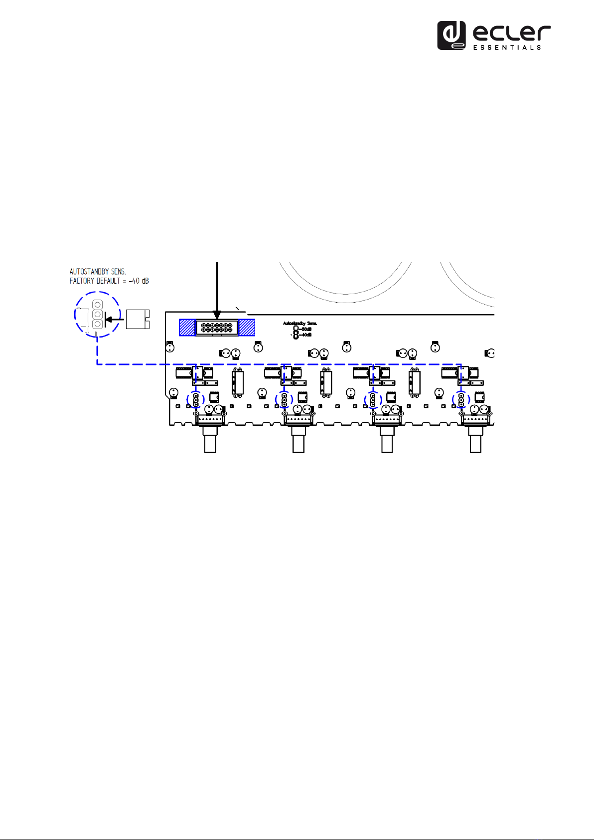
The detection threshold can be selected independently per channel by means of an internal
jumper. By default, it is in the -40dB position. If it is necessary to modify this threshold, it is
possible to set it at -50dB. The lower the threshold, the more likely it is that the amplifier
channel will come out of standby mode with very low signal levels, or even with
background noise in the wiring between the sound source and the amplifier, if this is
considerable.
If you detect that the auto standby function is regularly and/or unexpectedly activated (i.e.
even if there is valid sound content at the amplifier's input), before changing the threshold,
check that the input signal level setting is adequate. For this purpose, the SP (Signal
Present) LED should be active when an audio signal is present, and the CLIP LED should
not light up or light up occasionally in line with the bass frequencies, which have the
highest energy content.
If the problem persists (the input audio signal has a wide dynamic range, for example),
change the detection threshold. First, remove the top cover of the unit by unscrewing the
screws that hold it to the chassis, to access the connectors inside, then reposition the
jumper for the channel you want to change the threshold to.
5.5 Limiter circuit
This is an extra protection always enabled in the eHSA series amplifiers. This circuit
dynamically limits the input signal to avoid clipping of loud signals at the amplifier output; it
automatically reduces the input level not to exceed approximately 5% distortion.
The great utility of this circuit in any type of installation should be noted; the advantage of
this system over traditional compressors is that dynamics is practically not altered, due to its
time constant.

5.6 Output connections
The output section on the rear panel features Euroblock connectors.
Connection to high impedance lines: The loudspeakers line has to be connected to the
amplifier’s 0V and 70V terminals (70V line) or 0V and 100V terminals (100V line).
Connection on low impedance lines: The connection of the speaker line to the amplifier
should be made using the Lo-Z ("+" and "-") terminals.
Each output channel is independent, so you can use your high or low impedance
connection regardless of how the other outputs are connected.
If you want to combine, in the same channel, high and low impedance, using the 2
connectors of the same channel, you have to consider the load you are connecting to the
terminals, never exceeding the 60W that the amplifier can deliver. Thus, if a load of 4Ωis
connected to the low impedance connectors, it will not be possible to connect any
additional load to the 70/100V terminals (the amplifier will be protected), as the maximum
power transfer occurs to 4Ωand the amplifier delivers the available 60W to it. However, if
a load of 8Ωis connected to the low impedance connectors, a line of up to 30W can be
connected to the 70/100V terminals, as at 8 Ωhalf of the available power is delivered. The
rest of the available power can be delivered in lines connected to the same channel, never
between different channels.
Note:
the ground of the output connections are independent, never connect the "-" terminal
of the Lo-Z output together with the 0V terminal of the 70 / 100V line output.
The connection cable that joins the amplifiers outputs and the loudspeakers must be of
good quality, sufficient section and as short as possible. This is most important when the
distances to cover are long ones.

6. OPERATION AND USAGE
6.1 Start up
The red "PROT/STBY" LEDs light up when you turn on the power switch. A second after all
voltages have been stabilized and the amplifier is operating, "PROT/STBY" indicators turn
off.
In a complete audio installation, it is important to power on the equipment according to the
following sequence: sound sources (microphones, music players, etc.), mixers, equalizers,
active filters and power amplifiers. To power off, follow the reverse sequence.
6.2 Input attenuators
This consists of rotating potentiometers, situated on the front panel.
These attenuators allow connecting the amplifier to different types of mixers and processors,
independent level control and connection of speakers that can't handle the wattage supplied
by the output stage at full power, without risking damage if the volume of the preamplifier-
mixer is set too high.
6.3 Indicators
eHSA amplifiers include a simple yet effective indication system.
PROT/STBY indicators show the absence of loudspeaker output signal. These indicators
may light up for following reasons:
•During start-up, until the STANDBY time has passed. This time period is needed for
the internal operating voltages to settle.
•A short circuit is detected at the loudspeaker terminals (PROTECT function).
•When the module enters AUTO-STANDBY mode. In this case, the indicator will
illuminate in orange instead of red.
If these indicators remain lit in red, there's a malfunction that should be investigated to find
the cause of this lighting.

CLIP indicators light up when the signal level feeding the loudspeakers is just below the
actual clipping. This CLIP system takes into account possible variations in the supply
voltage, always giving a real indication. CLIP indicators light up to the beat of low
frequencies when working at high power levels; it's normal as low frequencies are those
with higher energy content. You must take care that these indicators do not remain
continuously lit.
SP Signal Presence indicators indicate the presence of a valid signal at the amplifier inputs.
7. CLEANING
The front panel should not be cleaned with dissolvent or abrasive substances because silk-
printing could be damaged. To clean it, use a soft cloth slightly wet with water and neutral
liquid soap; dry it with a clean cloth. Be careful that water never gets into the amplifier
through the holes of the front panel.

8. FUNCTION DIAGRAM

9. FUNCTION LIST
1. LED indicator of signal presence at the channel input: SP
2. Channel trim LED indicator: CLIP
3. Channel input attenuator: CH1, 2, 3…
4. LED indicator for overload protection and status STANDBY, PROT/STBY
5. LED indicator for linked inputs, LINK
6. AUTO STANDBY function switch
7. Power indicator ON
8. Euroblock connector channel input
9. LINK input link switch (1-2, 2-3, 3-4)
10. Euroblock connector low impedance Lo-Z channel output
11. Euroblock connector high impedance channel output (70/100V)
12. Network base
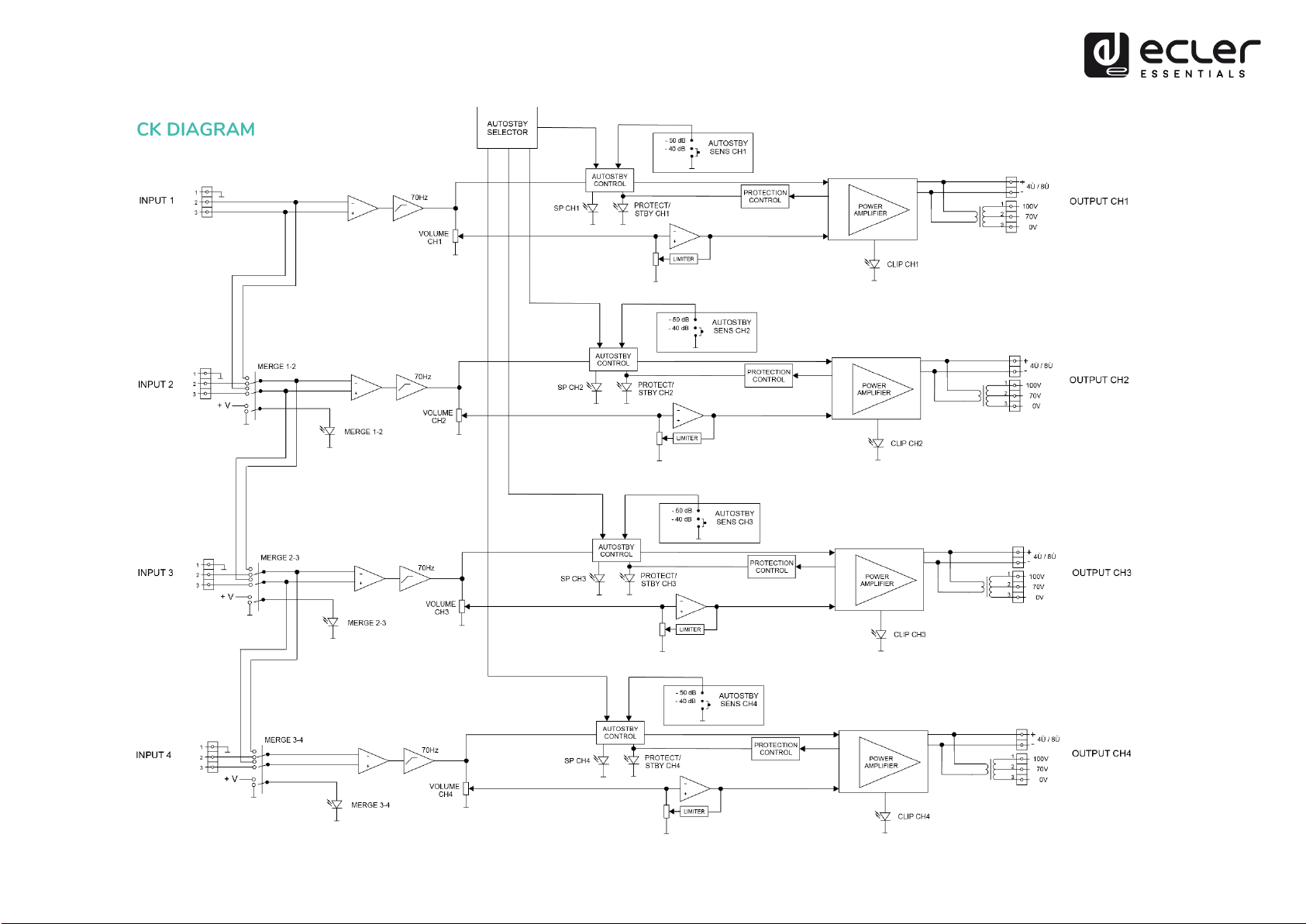
10. BLOCK DIAGRAM

15
11. TECHNICAL CHARACTERISTICS
eHSA4-60
Output power
Max output power¹ @ 4Ω
60W
Max output power¹ @ 100V
60W
Signal
Input sensitivity
0dBV
Input impedance
>20kΩ
Frequency response
Lo-Z output @ 4Ω: 70Hz - 30kHz (-3dB)
Hi-Z output @ 100V: 70Hz - 20kHz (-3dB)
THD + Noise
Lo-Z output @ 4Ω: <0,06%
Hi-Z output @ 100V: <0,1%
SNR
Lo-Z output @ 4Ω: >90dB
Hi-Z output @ 100V: >70dB
Channel crosstalk
>65dB @ 1kHz
Channel CMRR
>60dB @ 1kHz
AC Mains power
AC Mains requirement
100 – 240VAC, 50 – 60 Hz (±10%)
Power Consumption
Power Consumption (1/3 Power, @ 4Ω)
106W /115VA
Power Consumption (1/8 Power, @ 4 Ω)
52W / 68VA
Power Consumption (IDLE)
15W / 30VA
Power Consumption (STBY)
7,6W / 18VA
Settings
Auto stand-by threshold
40dB / 50dB, Internally Selectable
Auto stand-by time
90 seconds
Physical
Dimensions
(WxHxD)
482,6 mm x 44mm x 280mm / 19” x 1.7” x 11”
Weight
7,8 kg. / 17.2 lb.
1All channels driven @ 1%THD

16
All product characteristics are subject to variation due to production tolerances.
NEEC AUDIO BARCELONA S.L.
reserves the right to make changes or improvements in design or
manufacture that may affect these product specifications.
For technical queries please contact your supplier, distributor or complete the contact form on our website
under Support / Technical Query.
Motors, 166‐168 08038 Barcelona ‐ España ‐ (+34) 932238403 | informa[email protected]m | www.ecler.com
Table of contents
Other Ecler essentials Amplifier manuals

Ecler essentials
Ecler essentials eCA120HZ User manual

Ecler essentials
Ecler essentials HZA4-120F User manual

Ecler essentials
Ecler essentials eLPA Series User manual

Ecler essentials
Ecler essentials eLPA2-350 User manual

Ecler essentials
Ecler essentials eWAMPBT User manual

Ecler essentials
Ecler essentials eCA120 User manual
Popular Amplifier manuals by other brands


Sonifex
Sonifex Redbox RB-VHDA8 User handbook

Inter-m
Inter-m R-150 operating manual

Finkbiner Industries
Finkbiner Industries STUDIO HAVOC user manual

Belden
Belden GRASS VALLEY HDA-3911 Guide to installation and operation

Darkglass Electronics
Darkglass Electronics Microtubes B7K user manual

PYLE Audio
PYLE Audio PVA2 owner's manual