Ecler CKL110 User manual

USER MANUAL
MANUAL DE INSTRUCCIONES
MANUEL UTILISATEUR
CKL SERIES


3
CKL110 –LONG THROW SOUND SYSTEM
CKL SM115 –MID-LOW CKL SOUND REINFORCEMENT
1. IMPORTANT NOTE 04
1.1. Safety instructions 04
2. WARRANTY DESCRIPTION04
3. DESCRIPTION 05
3.1. CKL110 –LONG THROW SOUND SYSTEM 05
3.2. CKL SM115 –MID-LOW CKL110 SOUND REINFORCEMENT 05
4. APPLICATIONS 06
5. CONNECTIONS 06
6. AMPLIFICATION 07
6.1. Operation of one or two pairs of CKL110 speaker enclosures 07
6.2. Operation with more than two pairs of CKL speaker enclosures 08
6.3. Installation of CKL110 with CKL SM115 bass reinforcement enclosures 08
6.4. Rigging speaker enclosures 09
7. CONFIGURATIONS 10
7.1. Polar diagram 11
8. APPENDIX –BRIEF EXPLANATION OF ACOUSTIC CONCEPTS 12
8.1. Definition of acoustic parameters 12
8.1.1. Sound Pressure Level (SPL) 12
8.1.2. Acoustic absorption 12
8.2. Reverberation and reverberation time 13
8.2.1. Reverberation 13
8.2.2. Reverberation time (RT60)13
8.3. Speech intelligibility 14
9. TECHNICAL CHARACTERISTICS 42
9.1. Frequency response 43
10. DIAGRAMS 44
All numbers subject to variation due to production tolerances. ECLER S.A. reserves the right to make changes or improvements in
manufacturing or design which may affect specifications.

4
1. IMPORTANT NOTE
We thank you for trusting on us and choosing this Ecler product.
In order to obtain the maximum performance and perfect operation, it is VERY IMPORTANT that you
carefully read this manual before connecting the unit, taking special attention to the safety warnings here
described.
In this manual you will find a practical guide on how to correctly set up this product for the most common
applications. However, due to the versatility of the system, it is not possible to describe each and every
installation possibility. In case you need assistance for a special installation, Eclers Projects Department
Chapter 8. APPENDIX contains brief but concise explanations of frequently used terms in acoustics, which
are often used throughout this manual.
1.1. Safety instructions
HIGHLY DANGEROUS SOUND PRESSURE LEVELS
This family of acoustic enclosures easily produces sound pressure levels which may reach
120dB SPL at a distance of 10 metres (141dB SPL at 1m). This means that severe damage to
the auditory system can happen at a lower distance. Always make sure that the speakers are
not connected when working at their proximity.
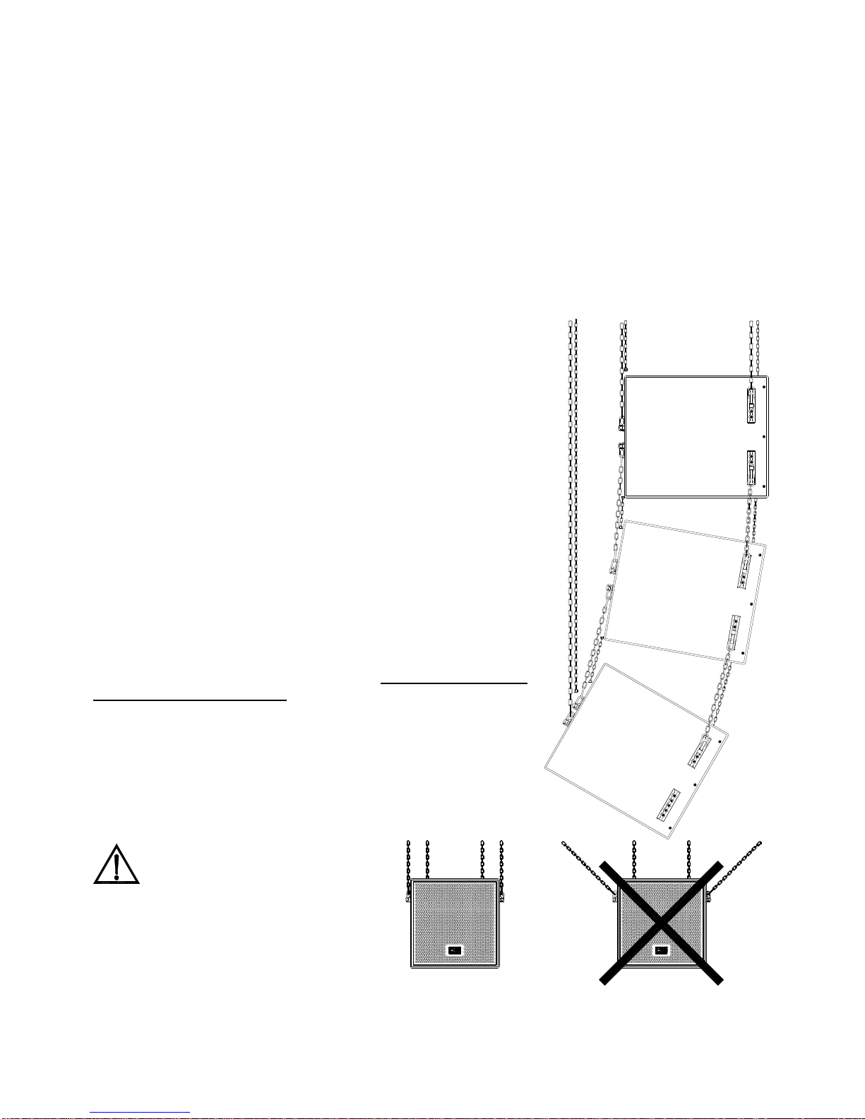
RIGGING OF ACOUSTIC ENCLOSURES
The enclosures should never be flown using different hardware than specified in this instruction
manual. Use only the hardware and rigging systems mentioned in this manual. Physical
integrity of people depend on that. Any rigging installation should be carried out, inspected and
approved by qualified professionals.
•No user adjustable parts exist inside these devices.
•Do not use this device in the proximity of water. Do not expose the device to splashings, and avoid
placing liquid containers on top of them.
•Do not place the device next to heat sources, lighting fixtures or stoves.
•Only use hardware accessories specified by the manufacturer.
•Keep the loudspeaker enclosures far away from magnetically sensitive devices, such as TV
screens, tape recorders or video recorders…
2. WARRANTY DESCRIPTION
Your ECLER equipment has undergone exhaustive laboratory and quality control tests before leaving
the factory. Nevertheless, your may be in need of our Technical Service during the period covered by
the Guarantee or afterwards. In that case, carefully protect your equipment in its original packing and
send it to our Technical Service with the transport and insurance paid. Attach a photocopy of your
Guarantee Certificate and a detailed description of the defect you have observed.
ECLER, S.A. guarantees its ECLER products against material or fabrication defects for a ONE-YEAR
period after the date of original purchase.
ECLER, S.A., will repair the defective equipment within the aforementioned period, with no charge for
parts and labour.
To ensure the validity of the Guarantee, it is essential that the attached Guarantee, Registration Card is
filled out correctly and remitted to your ECLER distributor, within 10 DAYS after date of purchase.
The Guarantee is non-transferable and protects the original buyer only.

5
The Guarantee does not cover:
•Damage caused by mistreatment or negligent handling, lack of elementary precautions, disregard
to the instructions in the manual, faulty connection or accidents.
•Equipment that has been manipulated, altered or repaired other than at the authorized Technical
Service centres.
•The exterior fittings and electro-mechanical parts, nor their wear due to use.
•Shipping and insurance expenses, nor for damages the set may incur during its transport.
ECLER, S.A., will not be held responsible for any direct or indirect damage, loss or other damage
originated by or relating to the equipment.
This Guarantee is valid only for repairs or services carried out at an authorized Technical Service
Centre.
3. DESCRIPTION
3.1. CKL110 –LONG THROW SOUND SYSTEM
Small-dimensioned trapezoidal acoustic enclosure for mid and high frequency reproduction. Assembled
with 18mm thick birch plywood from Finland covered with a scratch and shock resistant polyurethane
paint finish. Internally reinforced. The mid frequency way employs an enclosed 10’’ speaker with
neodymium motor and carbon fibre compound diaphragm attached to a Tractix horn, which is equipped
with a phase corrector. The high frequency way uses a 2’’ compression driver with pure titanium
diaphragm, neodymium motor and a 60º x40º constant directivity diffusor. The speakers are protected
against shocks, dust and splashes by a metal grille and an acoustically transparent foam.
The on-axis frequency response within a ±3dB margin lies between 170 Hz and 19 kHz.
The efficiency or sensitivity, which is sound pressure level (SPL) at 1m and 1W power input, reaches
remarkable 112dB. The maximum SPL produced at 1m reaches 141dB SPL.
The system includes a passive LC filter with low tolerance polyester capacitors and large cross-section
wire coils. The high frequency way also features a protection system against Larssen effect feedback
and signal clipping.
The maximum RMS power is 350W RMS at 8Ω, while the program power capacity is 700W at 8Ω.
3.2. CKL SM115 –MID-LOW CKL110 SOUND REINFORCEMENT
Low-dimensioned trapezoidal acoustic enclosure for mid and low frequency playback. Bandpass type
acoustical design. Assembled with 18 mm thick birch plywood from Finland covered with a scratch and
shock resistant polyurethane paint finish. Internally reinforced. It employs a high performance 15’’
speaker attached to a horn in order to increase efficiency. The speaker is protected against shocks, dust
and splashes by a metal grille and an acoustically transparent foam.
The on-axis frequency response within a ±3dB margin lies between 70Hz and 280Hz.
The efficiency or sensitivity, which is sound pressure level (SPL) at 1m and 1W power input, is 105dB.
The maximum SPL produced at 1m reaches 136dB SPL. An external active filter is required. (See
paragraph 6.3)
The maximum RMS power is 600W RMS at 8Ω, while the program power capacity is 1200W at 8Ω.

6
4. APPLICATIONS
The CKL110 has been designed for playback of vocal signals in fixed installations. It can be used alone
or together with the CKL SM115 (which has the same dimensions and shape) to extend the system’s
frequency response towards mid and low frequencies. Alone or together with the CKL SM115 the
system offers high efficiency levels. This makes it suitable for all applications where long throw of voice
signals is the main priority.
This type of enclosure is ideal for: stadiums, gyms, theatres, congress halls, houses of worship and
every space which requires long sound throwing and highly intelligible speech.
The CKL SM115 has been designed to extend the playback spectrum of the CKL110 towards the mid
and low frequencies. It can not be used as stand-alone. Its dimensions and shape are the same as
CKL110. It is suitable for all applications that require not only an optimal response at speech
frequencies, but also playback of musical signals.
5. CONNECTIONS
The cable between the amplifier outputs and the loudspeakers must be of good quality, enough cross-
section and as short as possible. This is very important when the distance is long and the load is low
(4-8Ω). We recommend a section of 2.5mm2or more for distances up to 10m and a section of 4 or 6 mm2
for longer distances. An easy way to known the required cross-section, assuming a 4% loss is using
following equation:
Lenght in m
Cross-sectión en mm2=
Loudspeaker impedance in Ω
Placed at the rear wall of the CKL enclosures is a connection panel which holds two SPEAKON®
sockets wired in parallel, facilitating interconnection of speaker enclosures.
SPEAKON® connectors have been adopted worldwide as the standard professional loudspeaker
connection, due to its reliability, immunity to vibration and durability.
Remember that the nominal impedance of CKL speakers is 8Ω. Therefore, when connecting two
enclosures in parallel, the impedance will drop to 4Ω, 2,66 Ω for tree enclosures and 2Ω for four
enclosures. Please check the value of the minimum load impedance your amplifier can handle, as not all
amplifiers adequately operate at 2Ω.
Operation at 2Ωconsiderably reduces the sound quality and the system efficiency; e.g., the loss on the
loudspeaker cable reduces the Damping Factor by a 76% because of operating at 2Ωinstead of 8Ω.
Almost all the amplifiers in the market base their operation at 2Ωon the use of destructive protections to
keep the components safe, with the penalty of sound quality. Also, and for both technological and power
supply constraints, the power gain involved in operation at 2Ωinstead of 4Ωis usually very low. ECLERs
SPM and SPM CHANNEL N amplifiers are able to operate at 2Ωkeeping its philosophy of non-destructive
protections and delivering every Watt the power supply is capable of.
ECLER, following the maximum sound quality criterion, recommend using the 2Ωconnections only in
installations where the amplifier will operate far from its maximum power.

7
Together with the CKL enclosure you will find a 4-way SPEAKON® cable connector. Always respect
polarity.
Make sure to securely plug in the SPEAKON® connector, i.e. fully inserting it to the socket and rotating
it to the right until noticing the locking mechanism.
6. AMPLIFICATION
6.1. Operation of one or two pairs of CKL110 speaker enclosures
Any amplifier capable of delivering an output power between 350W and 700W is perfectly suitable for
driving a pair of CKLs. Eclers amplification lines include several power amplifier models which can
perfectly fulfil this task. In case of operating two speaker enclosures in parallel, the required output
power of the amplifier should lie between 700W and 1400W at 4Ω.
This enclosure has been designed for the reproduction of voice signals mainly. If the enclosure is to be
installed in an acoustically deficient space (poor intelligibility, highly reverberant), it is recommended to
use an external active filter with a cut-off frequency lying between 140 and 170 Hz, keeping the high-
pass signal. Inside Eclers product range, two products can fulfil this need: The FAP30L, 2-way stereo
crossover with limiter or the UCM20 board, which can be directly installed inside the back of the APA
series of power amplifiers.
Remember that the CKL110 includes a passive filter which separates mid and high frequencies.
1+
1-
2+
2-
LIVE
GND
N.C.
N.C.
2-
1+
2+ 1-
APA SERIES POWER AMPLIFIER WITH INPUT
UCM20 UNIVERSAL CROSSOVER MODULE
STACKOUTPUT
LOUDSPEAKER
madeby ecler s.a. barcelona spain
CKL SERIES
CABINET
2- N.C.
1+
2+
1- GND
LIVE
N.C.
INPUT STACKOUTPUT
LOUDSPEAKER
madeby ecler s.a. barcelona spain
CKL SERIES
CABINET
2- N.C.
1+
2+
1- GND
LIVE
N.C.
INPUT STACKOUTPUT
LOUDSPEAKER
madeby ecler s.a. barcelona spain
CKL SERIES
CABINET
2- N.C.
1+
2+
1- GND
LIVE
N.C.
INPUT STACKOUTPUT
LOUDSPEAKER
madeby ecler s.a. barcelona spain
CKL SERIES
CABINET
2- N.C.
1+
2+
1- GND
LIVE
N.C.
INPUT

8
6.2. Operation with more than two pairs of CKL speaker enclosures
In case of working with 6, 8, 10 or more speaker enclosures, we recommend using a 2-channel amplifier
for each 2 or 4 speaker enclosures. The low level audio signal should be distributed from amplifier to
amplifier through their stack outputs. For this reason it is important to check if the amplifiers offer this
stacking possibility. All Ecler power amplifiers have this feature. Further considerations mentioned in the
previous paragraph also apply.
6.3. Installation of CKL110 with CKL SM115 bass reinforcement enclosures
As mentioned earlier, the CKL SM115 represents an ideal complement for the CKL110 in all those
situations where it is necessary to extend the frequency response of the system towards the bass end,
consequently improving the reproduction of music signals. This speaker enclosure does not include any
passive filter, meaning that the use of an external active crossover with tunable crossover frequency and
minimum filter slope of 18dB/oct (recommended 24dB/oct) is necessary. Inside Eclers product range,
two products can fulfil this need: The FAP30L, 2-way stereo crossover with limiter or the UCM20 board,
which can be directly installed inside the back of the APA series of power amplifiers.
The recommended crossover frequency is 150Hz.
INPUT
ACTIVE FILTER
STACKOUTPUT
LOUDSPEAKER
madeby ecler s.a. barcelona spain
CKL SERIES
CABINET
2- N.C.
1+
2+
1- GND
LIVE
N.C.
INPUT STACKOUTPUT
LOUDSPEAKER
madeby ecler s.a. barcelona spain
CKL SERIES
CABINET
2-N.C.
1+
2+
1-GND
LIVE
N.C.
INPUT STACKOUTPUT
LOUDSPEAKER
madeby ecler s.a. barcelona spain
CKL SERIES
CABINET
2- N.C.
1+
2+
1- GND
LIVE
N.C.
INPUT STACKOUTPUT
LOUDSPEAKER
madeby ecler s.a. barcelona spain
CKL SERIES
CABINET
2-N.C.
1+
2+
1-GND
LIVE
N.C.
INPUT
POWER AMPLIFIER POWER AMPLIFIER

9
No general rule exists for determining the number of CKL SM115 speakers required for a given number
of mid-high enclosures. This will depend greatly on the acoustics of the room or space where the
speakers are to be installed, in particular on reverberation time. Frequently, the reverberation time of
large rooms is very high, meaning that the reproduction of bass frequencies will add “mud” to the sound
quality and will have a negative effect on speech intelligibility. The CKL110 has been designed for
playback of vocal signals in fixed installations. It can be used alone or together with the CKL SM115
(which has the same dimensions and shape) to extend the system’s frequency response towards mid
and low frequencies. Alone or together with the CKL SM115 the system offers high efficiency levels.
This makes it suitable for all applications where long throw of voice signals is the main priority.
As a guideline for non-reverberant spaces, never install more than one CKL SM115 for each CKL110. In
the real world, many rooms are highly reverberant. In this case, installing for example 2 CKL SM115 for
8 CKL110 is perfectly enough. It could also be preferable not to install any CKL SM115 if the acoustics
of the room or space are very poor. Our Projects Department will help you out in finding the optimal
number of speaker enclosures that suit your requirements by drawing a virtual model and running a
computer simulation of your project.
6.4. Rigging speaker enclosures
Following general guidelines must be considered:
•Always place acoustic enclosures on solid and firm ground
•No obstacles should lie between the loudspeakers and the
audience
•High frequencies, as opposed to low frequencies, tend to be
much more directional and any obstacle in the acoustic wave
path represents attenuation in the frequency response of the
system.
The whole CKL range features an effective rigging system, the
same type as used in air cargo shipments (ISO 7166 standard),
consisting in 6 adjustable cargo rails, which allow flying single
speaker enclosures or complex combinations of several
enclosures. Two rails are placed at each side and two at the rear
wall of the cabinet. The fittings at the side are internally connected
with a metal brace. These side fittings allow flying the enclosure
and linking it to the next row of enclosures. Up to a maximum of 3
rows per column are allowed. Finally, the rear rails allow tilting the
enclosure or group of enclosures.
IMPORTANT
The rear rails have been designed basically for tilting the
enclosures. They should not carry any weight.
ATTENTION
The chains or steel cables used to
suspend the enclosures should
always run parallel to the vertical
axis of the loudspeaker cabinet. They must
not show a wider angle.

10
Each position of the aeronautic specified cargo restraint track has a maximum load capacity of 180kg,
considering the enclosure is correctly flown, as shown in the diagrams.
The tracking system works in combination with Ecler ADP cargo restraint double stud and ring. (Adam
Hall Ref. 5740)
The total load capacity of the structure is limited by this track and is 180kg per anchor point. (360kg
total)
It is very important to keep in mind that these values are only valid if the load is suspended
perpendicularly. Load capacity varies as a function of the angle according to following table:
Always make sure that the anchor points are firmly attached
to the rail and locked.
7. CONFIGURATIONS
Many aspects have to be considered when deciding the optimal electroacoustic reinforcement design for
a given space. All those aspects interact with each other, complicating the design stage even further.
More than a “cookbook” on sound system design and installation, this chapter describes several factors
which must be considered, as well as some guidelines which may help you to take the right decisions.
Unfortunately, acoustic principles are too often in conflict with aesthetic criterions. PA system designers
must admit and accept that the aesthetics of loudspeaker enclosures, in particular those designed for
high pressure levels, is not easily compatible with most designs. As a general rule for this kind of
situation it is recommended to find a single central sound radiation point. Ideally this would be done with
one single loudspeaker, but in practice, clusters or arrays including several more or less overlapping
loudspeakers must be used, according to the coverage and sound pressure requirements.
The first point to consider when deciding the location of the loudspeaker enclosures is the load capacity
of the suspension point. Secondly, the spot must be easily accessible for installation and later
maintenance tasks. On third place, the distance from the amplifier racks should be as short as possible,
and last but not least, acoustic design goals should be achieved.
The configuration you choose should basically depend on the desired SPL at the farthest audience point
and the required coverage width, while offering good frequency response characteristics. If the
efficiency of one loudspeaker is not enough to deliver a certain SPL at a given distance, more
enclosures must be aimed at that spot. The acoustic wave “beams” of the speakers can overlap more or
less, obtaining a maximum overlap if the enclosures are mounted parallelly, one on top of the other.
At the end of this manual you will find the polar diagrams for different cluster structures, both for the
horizontal and vertical planes. The diagrams show the coverage angle and relative on-axis SPL
compared to one single speaker enclosure. The table includes results for clusters of 1 to 6 horizontally
and 1 to 2 vertically arranged enclosures, with aperture angles of 12°(side-to-side) and 32°.
The enclosures are stacked together with minimum separation. The results are valid for the specified
frequencies. They are not valid for set-ups which include the CKL SM115 bass reinforcement enclosure.
Ángle 0º 45º 90º
Load capacity 180kg 170kg 160kg
0º
180kg 170kg
45º 160kg
90º

11
7.1. Polar diagram
The polar diagrams for the frequency bands of 500Hz and 2kHz and for each of the described
configurations can be found at the end of this manual.
As can be observed, the horizontal directivity of the cluster tends to narrow down as more CKL110 are
stacked together, while the vertical coverage angle tends to stay constant and equivalent to one single
CKL110 enclosure.
The polar diagrams show the expected behaviour for different enclosure configurations mounted in
angles of 12°(side by side) and 32°referenced to the normal of the enclosure. The effect of opening the
angle between enclosures represents an increase in coverage area.
For specialized configurations which do not match the set-ups here described, you can contact Eclers
projects department "[email protected]", where we will help you find the optimal configuration for your
installation requirements.
Please remind, no matter what kind of system you are installing, that it is essential to follow all safety
instructions exposed in this manual.
Note: All polar diagrams are normalized on-axis.

12
8. APPENDIX –BRIEF EXPLANATION OF ACOUSTIC CONCEPTS
The following paragraphs give brief explanations of frequently used concepts in acoustics, which will
help you understand the problematic involved in designing high-quality PA systems.
8.1. Definition of acoustic parameters
8.1.1. Sound Pressure Level (SPL)
Defined as:
6
10
·
20
log20 −
=efp
SPL (dB SPL)
The numerator corresponds to the effective sound pressure.
The denominator corresponds to the hearing threshold, i.e. the minimum sound pressure which causes
hearing sensation in the human auditory system.
Following table shows the sound pressure levels of several typical sound sources, together with their
subjective level sensation.
SOUND SOURCE SOUND PRESSURE
LEVEL (dB SPL) SUBJECTIVE LEVEL
SENSATION
Jet take-off 120
Construction works 110
Pneumatic drill 100 Very high
Heavy truck (at 15m) 90
City street 80
Inside car 70 High
Normal conversation 60
Office 50
Living room 40 Moderate
Bed room (al night) 30
Recording studio 20 Low
Typical sound pressure levels (dB SPL)
8.1.2. Acoustic absorption
The acoustic absorption coefficient is defined as the ratio between absorbed acoustic energy by a
certain material and incident acoustic energy.
i
abs
E
E
=α
Values of αrange between 0 (no absorption) and 1 (maximum absorption). The absorption
characteristics of construction materials used for acoustic treatment of rooms, determine, amongst other
factors, the resulting reverberation time. (see paragraph 8.2.2)

13
8.2. Reverberation and reverberation time
8.2.1. Reverberation
When a sound is generated inside a closed space, all room surfaces produce a series of reflections.
The magnitude of these reflections fades out more or less quickly as time passes.
The speed of this sound decay depends on the absorption characteristics of the room surfaces. The
higher the absorption, the quicker the attenuation. The amount of decaying sound once the sound
source has stopped emitting is called reverberation.
Example of sound pressure decay as a function of time.
A room with large amounts of reverberation is also called a “live” room (factory plant, church, sports
arena, etc.), as opposed to an acoustically “dead” or “dry” room, where the decay of the reverberation is
much quicker. (recording studio, voice booth, etc.)
The parameter that quantifies the amount of reverberation inside a closed space is known as
reverberation time, commonly expressed as RT60.
8.2.2. Reverberation time RT60
The RT60 is defined as the time necessary for the sound pressure to decay 60dB below the initial
pressure level before the sound source stopped emitting.
Generally speaking, the RT60 varies with frequency, tending to be shorter as frequency rises. This is in
part caused by the higher absorption coefficient at high frequencies of commonly employed acoustic
treatments. Air absorption and low relative humidity are also responsible for this effect, but are
especially important in very large spaces.
As just mentioned, RT60 is a function of frequency, but often one single value (the average of
reverberation times at 500Hz and 2kHz, RTmid) is given as a reference for characterizing the
reverberation of a room.

14
Following table shows recommended RTmid values for different types of rooms:
ROOM TYPE RTMID, fully occupied room (en sec.)
Conference room 0.7 –1.0
Cinema theatre 1.0 –1.2
Multifunctional room 1.2 –1.5
Opera theatre 1.2 –1.5
Concert Hall (chamber music) 1.3 –1.7
Concert Hall (symphonic music) 1.8 –2.0
Church (organ and choral music) 2.0 –3.0
Radio voice booth 0.2 –0.4
Recommended RTmid value ranges for various types of rooms.
Calculation of RT60
Although several methods for the calculation of reverberation time exist, the most widespread is the classic
Sabine equation:
A
V
RT 161.0=
Where V is the volume and A is the total absorption of the room.
8.3. Speech intelligibility
The main objective when designing a room destined for speech reproduction, be it with or without
electroacoustic reinforcement, is that the message must be clearly understood by all the audience.
Many research efforts have been put in subjectively determining the degree of intelligibility inside a
room. In the early 70s, the Dutch acoustician V.M.A. Peutz carried out a comprehensive research which
gave place to an equation that puts speech intelligibility as a function of room acoustics. The parameter
is called %ALcons.
Following table shows a range of %ALcons values and their corresponding subjective intelligibility
degree, according to Peutz’s equation:
Subjective intelligibility degree, according to Peutz.
%ALCons Subjective intelligibility degree
Between 0 y -3 % Excellent
Between -3 y -7 % Very good
Between -7 y -10 % Good
Between -10 y -15 % Acceptable
Between -15 y -30 % Poor
Less than de -30% Unacceptable

15
Amongst others, following factors determine the degree of speech intelligibility inside a room:
•Bandwidth and frequency response of the electroacoustic system.
•Signal level and signal to noise ratio (S/N).
•Reverberation time, RT60.
•Room geometry.
•Directivity and orientation of loudspeaker enclosures.
•Coverage uniformity: Variations in sound pressure level throughout the audience are should not
exceed ±3dB SPL.
•Listener attitude.
As a general rule, the group of reflections arriving at the listener in the first 35 to 50ms after the direct
sound positively contribute to speech intelligibility. Conversely, reflections arriving more than 50ms later
than the direct sound will be interpreted as echoes, negatively affecting the comprehension of the
spoken message.
Following measures can be taken to enhance intelligibility:
•Make sure the bandwidth of the PA system is wide enough at speech frequencies (flat response
between 250 and 12 kHz).
•Minimize the distance between loudspeakers and audience.
•Avoid delays greater than 50ms coming from different speakers.
•Use highly directional loudspeakers in reverberant spaces.
•Use a suitable equalization.
Typical equalization for speech intelligibility enhancement.

16
CKL110 -LONG THROW SOUND SYSTEM
CKL SM115 –MID-LOW CKL110 SOUND REINFORCEMENT
1. NOTA IMPORTANTE 17
1.1. Precauciones de seguridad 17
2. DESCRIPCIÓN DE LA GARANTÍA 17
3. DESCRIPCIÓN 18
3.1. CKL110 -LONG THROW SOUND SYSTEM
Sistema de sonido de largo alcance 18
3.2. CKL SM115 -MID-LOW CKL110 SOUND REINFORCEMENT
Refuerzo de medios-graves para CKL110 18
4. APLICACIONES 19
5. CONEXIONADO 19
6. AMPLIFICACIÓN 20
6.1. Funcionamiento de una pareja o dos parejas de cajas CKL110 20
6.2. Funcionamiento con más de dos parejas de CKL110 21
6.3. Instalación de CKL110 con recintos de apoyo CKL SM115 21
6.4. Suspensión de cajas 22
7. CONFIGURACIONES 23
7.1. Diagrama polar 24
8. APÉNDICE -BREVE EXPLICACIÓN DE CONCEPTOS ACÚSTICOS 25
8.1. Definición de parámetros acústicos 25
8.1.1. Nivel de presión sonora (SPL) 25
8.1.2. Absorción acústica 25
8.2. Reverberación y tiempo de reverberación 26
8.2.1. Reverberación 26
8.2.2. Tiempo de reverberación (RT60)26
8.3. Inteligibilidad de la palabra 27
9. CARACTERÍSTICAS TÉCNICAS 42
9.1. Respuesta en frecuencia 43
10. DIAGRAMAS 44
Todos los datos están sujetos a variación debida a tolerancias de producción. ECLER S.A. se reserva el derecho de realizar cambios o
mejoras en la fabricación o diseño que pudieran afectar las especificaciones.

17
1. NOTA IMPORTANTE
Agradecemos su confianza por haber elegido este producto Ecler.
Para conseguir la máxima operatividad y adecuado rendimiento, es MUY IMPORTANTE antes de su
conexión, leer detenidamente y tener muy presentes las consideraciones que aquí se especifican.
En este manual encontrará una práctica guía para instalar correctamente el producto en sus
aplicaciones más comunes. Sin embargo dadas sus características resulta imposible recoger aquí todas
las posibilidades de instalación. Para montajes especiales le ofrecemos la posibilidad de contactar con
óptima según sean los requerimientos de la instalación.
También encontrará en el apartado 8. APÉNDICE, una breve y clarificadora explicación de los
conceptos acústicos comúnmente empleados y que aparecen con frecuencia en éste manual.
1.1. Precauciones de seguridad
NIVELES DE PRESIÓN SONORA ALTAMENTE PELIGROSOS
Esta familia de recintos acústicos es capaz de entregar niveles de presión sonora que incluso
a distancias de 10 metros pueden alcanzar los 120dB SPL (141dB SPL a 1m). Ello significa
que a distancias inferiores pueden causar lesiones auditivas graves. Asegúrese siempre de
que los recintos no están conectados cuando trabaje en sus proximidades.
SUSPENSIÓN DE RECINTOS
En ningún caso deben suspenderse los equipos utilizando accesorios distintos de los
especificados en éste manual de instrucciones. Utilice únicamente los accesorios y los
sistemas de volado especificados en el presente manual. La integridad física de las personas
puede depender de ello. Toda instalación de colgado debe ser realizada, inspeccionada y aprobada por
personal cualificado.
•No existen partes ajustables por el usuario en el interior de estos equipos.
•No utilice este aparato cerca del agua. No exponga los equipos a salpicaduras, evite colocar
recipientes que contengan líquidos sobre ellos.
•Evite colocar los equipos cerca de fuentes de calor, focos o estufas.
•Utilizar únicamente accesorios especificados por el fabricante.
•Mantenga alejadas las cajas acústicas de equipos sensibles a campos magnéticos tales como
monitores de TV, magnetoscopios, magnetófonos...
2. DESCRIPCIÓN DE LA GARANTÍA
Su equipo ECLER ha superado ensayos de laboratorio y exhaustivos controles de calidad antes de
abandonar la fábrica. No obstante podría darse el caso de que necesite nuestro Servicio Técnico
durante el periodo que cubre la garantía o posteriormente. En tal caso, proteja cuidadosamente la
unidad en su caja original y envíela a nuestro Servicio Técnico con los gastos y el seguro pagados.
Adjunte una fotocopia del certificado de garantía y una descripción detallada del defecto observado.
ECLER, S.A. garantiza sus productos ECLER ante defectos de materiales o fabricación durante el
periodo de UN AÑO.
ECLER, S.A. reparará el equipo defectuoso dentro del periodo especificado, sin cargo alguno para
piezas y mano de obra.
Para asegurar la validez de la garantía es preciso que la Garantía y la Tarjeta de Registro se rellenen
correctamente y se remitan a su distribuidor ECLER, en el plazo de 10 días después de la fecha de
compra.
La garantía no es transferible y solamente protege al comprador original.

18
La garantía no cubre:
-Daños ocasionados por malos tratos o manejo negligente, falta de cuidados elementales, desatención
de las instrucciones del manual, conexión equivocada o accidentes.
-Aparatos que hayan sido manipulados, alterados o reparados fuera del Servicio Técnico autorizado.
-El mueble exterior, los componentes electromecánicos ni su desgaste por uso.
-Los gastos de envío y seguros, ni los daños que el aparato pueda sufrir durante el transporte.
ECLER, S.A., no será responsable por ningún daño directo o indirecto, pérdida o perjuicio originado por
o en relación con el equipo.
Esta garantía es válida sólo si las reparaciones o servicios se realizan en un Servicio Técnico
autorizado.
3. DESCRIPCIÓN
3.1. CKL110 -LONG THROW SOUND SYSTEM -Sistema de sonido de largo alcance
Recinto acústico trapezoidal de contenidas dimensiones destinado a la reproducción de frecuencias
medias y agudas. Realizado en contraplacado de abedul finlandés de 18mm de grosor recubierto de
una pintura de poliuretano resistente a rayas y pequeños golpes. Internamente reforzado. Para la vía de
medios equipa un altavoz de 10” con carcasa cerrada, imán de neodimio y membrana de compuesto de
fibra de carbono acoplado a una bocina tipo Tractix equipada con corrector de fase para la vía de
medios. Para la vía de agudos monta un transductor a compresión de 2” con membrana de titanio puro,
motor de neodimio y difusor de directividad constante de 60º x 40º para la vía de agudos. Los altavoces
están protegidos de golpes, polvo y salpicaduras mediante una reja y espuma acústicamente
transparente.
Su respuesta en frecuencia no varía más de ±3dB de 170Hz a 19KHz. en el eje.
Su nivel de eficiencia, nivel de presión sonora SPL a 1 metro y con una potencia a la entrada de 1W,
alcanza la espectacular cifra de 112dB. El máximo nivel de presión sonora, SPL, capaz de entregar a
un metro de distancia es de 141dB SPL.
Incorpora un elaborado filtro pasivo del tipo LC con condensadores de poliéster de baja tolerancia y
bobinas fabricadas con hilo de gran sección. Asimismo se ha incorporado un sistema de protección de
la vía de agudos contra el efecto Larsen o recortes de señal.
La potencia admisible continua es de 350W RMS a 8Ω. Mientras que la capacidad de potencia de
programa es de 700W a 8Ω.
3.2. CKL SM115 -MID-LOW CKL110 SOUND REINFORCEMENT
Refuerzo de medios-graves para CKL110
Recinto acústico trapezoidal de contenidas dimensiones destinado a la reproducción de frecuencias
medias bajas. Arquitectura acústica del recinto de tipo “band pass”. Realizado en contraplacado de
abedul finlandés de 18mm de grosor recubierto de una pintura de poliuretano resistente a rayas y
pequeños golpes. Internamente reforzado. Equipa un altavoz de 15” de altas prestaciones acoplado a
una bocina para aumentar el rendimiento. El altavoz está protegido de golpes, polvo y salpicaduras
mediante una reja y espuma acústicamente transparente.
Su respuesta en frecuencia no varía más de ±3dB de 70Hz a 280Hz en el eje.
El nivel de eficiencia, nivel de presión sonora SPL a 1 metro y con una potencia a la entrada de 1W, es
de 105dB. El máximo nivel de presión sonora, SPL, capaz de entregar a un metro de distancia es de
136dB SPL Requiere filtro activo exterior. (Ver apartado 6.3.)
La potencia admisible continua es de 600W RMS a 8Ω. Mientras que la capacidad de potencia de
programa es de 1200W a 8Ω.

19
4. APLICACIONES
La CKL110 ha sido diseñada para la reproducción de señales vocales en instalaciones permanentes.
Puede usarse sola o complementada de la CKL SM115 (de idénticas dimensiones y forma) para
extender la respuesta en frecuencia del sistema hacia las frecuencias medias graves. Sola o formando
un conjunto con la CKL SM115 ofrece muy elevados niveles de eficiencia. Es pues idónea para todas
aquellas aplicaciones en las que la prioridad sea la proyección de voz a larga distancia.
Este tipo de recintos resulta ideal para: Estadios, Polideportivos, Teatros, Salones de congresos.
Lugares destinados al culto y cualquier espacio en el que sea necesario proyectar sonido, priorizando la
inteligibilidad de la voz, a largas distancias.
La CKL SM115 ha sido diseñada para extender el espectro de reproducción de la CKL110 hacia las
medias-bajas frecuencias. No puede pues usarse sola. Tiene idénticas dimensiones y forma que la
CKL110. Es idónea para todas aquellas aplicaciones en las que además de una óptima reproducción de
la banda de frecuencias de voz sea necesario reproducir señales musicales.
5. CONEXIONADO
El cable de conexión que une las salidas del amplificador y los altavoces deberá ser de buena calidad,
de suficiente sección y lo más corto posible; esto reviste importancia especial cuando las distancias a
cubrir son grandes y la carga es baja (4-8Ω): hasta 10m se recomienda una sección no inferior a
2,5mm²y para distancias superiores, 4 ó 6mm². Una forma fácil de determinar la sección requerida,
asumiendo unas pérdidas aproximadas del 4%, es mediante la siguiente fórmula:
Longitud en m
Sección en mm2=
Impedancia del altavoz en Ω
Las CKL montan un panel de conexiones en el panel posterior que incluyen dos conectores
SPEAKON® montados directamente en paralelo para posibilitar así una fácil interconexión de recintos.
Los conectores SPEAKON® han sido adoptados mundialmente como estándar por proporcionar una
conexión fiable y totalmente inmune a vibraciones y al paso del tiempo.
Recuerde que las CKL tienen una impedancia nominal de 8Ω. Así en el caso de trabajar con dos cajas
en paralelo el conjunto operará a 4Ω, en el caso de 3 cajas a 2,66Ωy en el caso de 4 cajas a 2Ω.
Asegúrese de cuál es la limitación de su amplificador en nivel de impedancia de carga pues no todos
los amplificadores trabajan satisfactoriamente a 2Ω.
Trabajar a 2Ωdisminuye considerablemente la calidad de sonido y el rendimiento del sistema, por
ejemplo, las pérdidas en el cable de altavoz reducen el factor de amortiguamiento (damping factor) en
un 76% por el hecho de trabajar a 2Ωen lugar de a 8Ω. La práctica totalidad de amplificadores
existentes en el mercado basan su funcionamiento a 2Ωen salvaguardar mediante protecciones
destructivas la integridad de los componentes, quedando afectada notablemente la calidad de sonido
del amplificador. Paralelamente y por limitaciones de tipo tecnológico y de alimentación, los incrementos
de potencia por pasar de 4Ωa 2Ωsuelen ser muy pequeños. Los amplificadores SPM ECLER y
SPM CHANNEL N pueden trabajar a 2Ωmanteniendo su filosofía de protecciones no destructivas y
entregando toda la potencia que su alimentación es capaz de suministrar, con la única limitación de sus
protecciones.
ECLER, siguiendo los criterios de máxima calidad de sonido, recomienda utilizar tan sólo la conexión a
2Ωen aquellas instalaciones que vayan a trabajar lejos de la máxima potencia.

20
Acompañando a las CKL encontrará un conector SPEAKON® aéreo de 4 contactos. Respete siempre
la polaridad.
Asegúrese de enclavar correctamente el conector SPEAKON®, esto es insertándolo hasta el fondo
(sólo entra en una posición) y girando hacia la derecha hasta que note que queda bloqueado.
6. AMPLIFICACIÓN
6.1. Funcionamiento de una pareja o dos parejas de cajas CKL110
Cualquier amplificador capaz de entregar una potencia comprendida entre 350W y 700W a 8Ωes
perfectamente adecuado para amplificar una pareja de CKL. Dentro de las diversas líneas de
amplificación Ecler encontrará varios modelos capaces de realizar con perfecta eficacia este cometido.
En el caso de trabajar con dos cajas en paralelo la potencia necesaria estaría comprendida entre los
700 y 1400W a 4Ω.
Dado que la caja está destinada a la reproducción de la voz se recomienda, en el caso de que deba
funcionar en espacios con deficiente inteligibilidad (altamente reverberantes) utilizar un filtrado activo de
la señal de entrada, con una frecuencia de corte recomendada entre 140 y 170Hz, tomado la señal de
paso alto. Dentro de la gama de producto Ecler encontrará dos alternativas para realizar este cometido:
el FAP30L, crossover estéreo de dos vías que además incorpora limitador o la tarjeta UCM20 que se
monta directamente en el posterior de los amplificadores de la serie APA.
Recuerde que la CKL110 incorpora un filtro pasivo para realizar la separación de frecuencias
medias/agudas.
1+
1-
2+
2-
LIVE
GND
N.C.
N.C.
2-
1+
2+ 1-
APA SERIES POWER AMPLIFIER WITH INPUT
UCM20 UNIVERSAL CROSSOVER MODULE
STACKOUTPUT
LOUDSPEAKER
madeby ecler s.a. barcelona spain
CKL SERIES
CABINET
2- N.C.
1+
2+
1- GND
LIVE
N.C.
INPUT STACKOUTPUT
LOUDSPEAKER
madeby ecler s.a. barcelona spain
CKL SERIES
CABINET
2- N.C.
1+
2+
1- GND
LIVE
N.C.
INPUT STACKOUTPUT
LOUDSPEAKER
madeby ecler s.a. barcelona spain
CKL SERIES
CABINET
2- N.C.
1+
2+
1- GND
LIVE
N.C.
INPUT STACKOUTPUT
LOUDSPEAKER
madeby ecler s.a. barcelona spain
CKL SERIES
CABINET
2- N.C.
1+
2+
1- GND
LIVE
N.C.
INPUT
This manual suits for next models
1
Table of contents
Languages:
Other Ecler Stereo System manuals