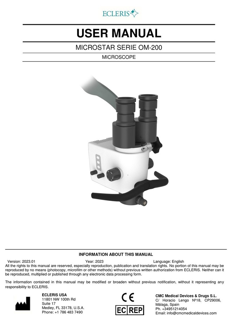
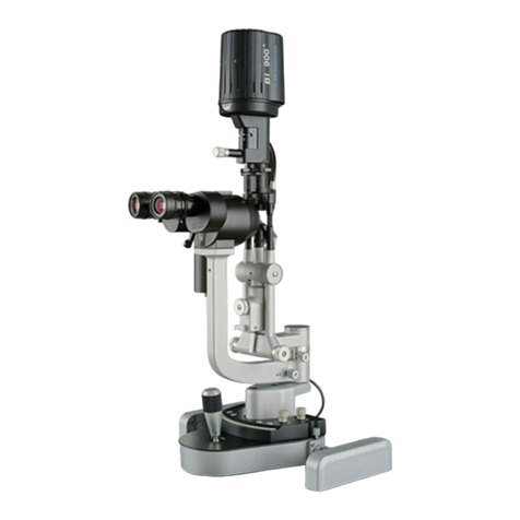
Ecleris MICROSTAR OM-100 User manual

INMANUUIN158 Rev.2019.04.01 / ENG
USER MANUAL
MICROSTAR SERIE OM-100
MICROSCOPE
ABOUT THIS MANUAL
Version: 2019.04.01
Year: 2019
Language: English
All the rights to this manual are reserved, especially reproduction, publication and translation rights. No portion of this manual may be
reproduced by no means (photocopy, microfilm or other methods) without previous written authorization from ECLERIS. Neither can it
be reproduced, multiplied or published through any electronic data processing form.
The information contained in this manual may be modified or broaden without previous notification, without it representing any
responsibility to ECLERIS.
EUSA GLOBAL Llc.
11801 NW 100th Rd
Suite 17
Medley, FL 33178, U.S.A.
Phone: +1 786 483 7490
CMC Medical Devices & Drugs S.L.
C/ Horacio Lengo Nº18, CP29006, Málaga,
Spain
Ph. +34951214054
Email: info@cmcmedicaldevices.com

USER MANUAL –MICROSTAR
Page 2of 31
INMANUUIN158 Rev.2019.04.01 / ENG
TABLA OF CONTENT
1. SYMBOLS................................................................................................................................4
2. SAFETY INFORMATION.........................................................................................................4
2.1 WARNINGS..........................................................................................................................4
3. DESCRIPTION.........................................................................................................................5
3.1 INTENDED USE...................................................................................................................5
3.2 INTENDED USER ................................................................................................................5
3.3 DESCRPTION AND COMPONENTS...................................................................................5
3.3.1 FLOOR STAND MODEL (OM-100F).............................................................................5
3.3.2 WALL-MOUNTED MODEL (OM-100W).........................................................................6
3.3.3 CEILING-MOUNTED MODEL (OM-100C).....................................................................7
3.3.4 TABLE-MOUNTED MODEL (OM-100T)........................................................................8
3.3.5 COMPLETE HEAD BODY.............................................................................................9
3.3.6 LIGHT SOURCE..........................................................................................................10
3.3.6.1 LED LIGHT SOURCE..............................................................................................10
3.3.6.2 XENON LIGHT SOURCE.........................................................................................10
3.3.6.3 HALOGEN LIGHT SOURCE....................................................................................10
3.3.7 COMPATIBLE ACCESORIES.....................................................................................10
4. INSTALLATION AND SET UP ...............................................................................................11
4.1 FLOOR STAND MODEL –OM100F...................................................................................11
4.2 LIGHT SOURCE.................................................................................................................14
4.3 FOCAL LENS MOUNTING.................................................................................................15
4.4 WALL-MOUNTED MODEL –OM100W..............................................................................15
4.5 CEILING-MOUNTED MODEL –OM100C ..........................................................................17
4.6 TABLE-MOUNTED MODEL –OM-100T.............................................................................19
4.7 BEAM SPLITTER AND CAMERA INSTALLATION.............................................................19
4.7.1 IMAGE ORIENTATION................................................................................................21
4.8 REVISION..........................................................................................................................22
5. OPERATION –FUNCTIONS .................................................................................................22
5.1 MICROSCOPE OPERATION.............................................................................................22
5.2 LIGHT SOURCE.................................................................................................................22
5.3 INTERPUPILLARY DISTANCE ADJUSTMENT..................................................................23
5.4 DIOPTRIC CORRECTION ADJUSTMENT.........................................................................23
5.5 MAGNIFICATION VARIATION...........................................................................................23
5.6 COLOR FILTER .................................................................................................................23
6. MANIPULATION & MOVEMENTS.........................................................................................23
6.1 FOREARM MOVEMENT....................................................................................................23
6.2 PARALLELOGRAM ARM MOVEMENT..............................................................................24

USER MANUAL –MICROSTAR
Page 3of 31
INMANUUIN158 Rev.2019.04.01 / ENG
6.3 ROTATIONAL MOVEMENT OF THE HEAD ......................................................................24
6.4 HEAD ROTATION AXIL .....................................................................................................24
6.5 HEAD TILT.........................................................................................................................24
6.6 SHIPMENT.........................................................................................................................24
7. MAINTENANCE.....................................................................................................................25
7.1 CLEANING.........................................................................................................................25
7.1.1 CLEANING THE EXTERNAL SURFACES..................................................................25
7.1.2 CLEANING OF OBJECTIVE LENS AND EYEPIECES................................................25
7.2 ELECTRICAL CONNECTIONS..........................................................................................25
7.3 LAMP CHANGE .................................................................................................................26
7.4 FUSE CHANGE..................................................................................................................26
7.5 FIBER OPTIC CABLE CHANGE ........................................................................................27
8. TECHNICAL ESPECIFICATIONS..........................................................................................27
9. TROUBLESHOOTING...........................................................................................................30
10. TECHNICAL SERVICE.......................................................................................................30
11. WARRANTY.......................................................................................................................31

USER MANUAL –MICROSTAR
Page 4of 31
INMANUUIN158 Rev.2019.04.01 / ENG
1. SYMBOLS
Read the related documentation
Manufacturer Identification
(Name, Address)
Alternate current
Catalogue number
Protect against water
Serial number
This side up
Manufacturing date
(MM/YYYY)
Fragile
Do not discard with the
household waste
CE mark
EU Authorized
Representative
2. SAFETY INFORMATION
2.1 WARNINGS
This symbol shall be used in this manual to indicate information that includes warnings or
important precautions.
Please, read the manual thoroughly before operating the equipment.
Should you have any doubt regarding the contents of the manual herein or the equipment
operation and safety, please contact your local distributor or the closest ECLERIS office.
The EclerisMicrostarOM-100 Microscope is an electrical device that provides very high light
intensity. It is use is recommended exclusively for trained personnel.
Do not use the microscope in places where there is explosion danger.
Although the light source does not damage the eyes, it is recommend not to look directly into the
light channel or the end of the microscope and handling it according to instructions.
The Ecleris Microstar OM-100 Microscope is grounded through a conductor of the AC interlock
cable. This essential cable grounding is provided for a safe operation of the equipment.
In case of electromagnetic interference with other electromedical or electrical equipment, widen
the distance between the microscope and the other device in order to minimize these effects.
If as a consequence of:
Inadequate use of the equipment.
No use of this manual.
Poor care and maintenance of the equipment.
Repair and manipulation by unauthorized personnel.
…any material or personal damage were caused to third parties, ECLERIS, the manufacturer and
the supplier of the equipment, shall not assume any responsibility for such damages.

USER MANUAL –MICROSTAR
Page 5of 31
INMANUUIN158 Rev.2019.04.01 / ENG
3. DESCRIPTION
3.1 INTENDED USE
The OM-100 Microscope has been designed to perform diagnostic observation. It is used in
different medical specialties, as well as dentistry; where a magnification of the working field is
necessary to ensure the success of the treatment/diagnosis.
3.2 INTENDED USER
The intended users of this device are doctors or other health professionals.
3.3 DESCRPTION AND COMPONENTS
The ECLERIS MICROSTAR Series OM-100 Microscope has been designed for diagnostic
observations.
The purpose of this manual is to explain the functioning and operation of the equipment.
Its use is indicated for different medical specialties and odontology assisting the professionals by
obtaining a magnified view of the working area and allowing them to achieve a better
performance.
The availability of different models of the ECLERIS MICROSTAR Series OM-100 Microscope
together with the compatibility of all its accessories allows this device to achieve all the necessary
characteristics for different specialties.
3.3.1 FLOOR STAND MODEL (OM-100F)
Components:
4 Wheels with brakes
1 Base and column
1 27mm Bolt with washer
1 Complete pantograph arm
1 Light Source
1 Head with 1 objective lens
1 Binocular
2 Eyepieces
1 60º angled piece
1 Fiber optic cable
1 3 meters AC Interlock cable
1 Cover
1 User’s manual
1 3/16 Allen key
1 4mm Allen key

USER MANUAL –MICROSTAR
Page 6of 31
INMANUUIN158 Rev.2019.04.01 / ENG
1. Wheels with brake
2. Base
3. Column
4. Head
5. Binocular
6. Eye piece
7. 60º angled piece
8. Parallelogram arm brake
9. Parallelogram arm
10. Weight compensation command
11. Fiber optic cable
12. Forearm
13. Double light source
3.3.2 WALL-MOUNTED MODEL (OM-100W)
Components:
1 Wall mount
4 Wall anchors with 4 bolts
1 Complete pantograph arm
1 Light Source
1 Head with 1 objective lens
1 Binocular
2 Eyepieces
1 60° angled piece
1 Fiber optic cable
1 3 meters AC Interlock cable
1 Wall-mount power cable
1 Cover
1 User’s manual
1 3/16 Allen key
1 4mm Allen key

USER MANUAL –MICROSTAR
Page 7of 31
INMANUUIN158 Rev.2019.04.01 / ENG
1. Double light source
2. Forearm
3. Parallelogram arm
4. 60º angled piece
5. Head fork pole
6. Eye piece
7. Binocular
8. Head
9. Wall mount
3.3.3 CEILING-MOUNTED MODEL (OM-100C)
Components:
1 Ceiling mount
1 Extensible Column
1 Complete pantograph arm
1 Light Source
1 Head with 1 objective lens
1 Binocular
2 Eyepieces
1 60° angled piece
1 Fiber optic cable
1 3 meters AC Interlock cable
1 Cover
1 User’s manual
1 3/16 Allen key
1 4mm Allen key

USER MANUAL –MICROSTAR
Page 8of 31
INMANUUIN158 Rev.2019.04.01 / ENG
1. Double light source
2. Forearm
3. Ceiling-mount
4. Telescopic column (inside
tube)
5. Telescopic column (external
sheath)
6. Parallelogram arm
7. 60º angled piece
8. Head
3.3.4 TABLE-MOUNTED MODEL (OM-100T)
Components:
1 Table mount
1 Column
1 Complete pantograph arm
1 Light Source
1 Head with 1 objective lens
1 Binocular
2 Eyepieces
1 60° angled piece
1 Fiber optic cable
1 3 meters AC Interlock cable
1 Cover
1 User’s manual
1 3/16 Allen key
1 4mm Allen key

USER MANUAL –MICROSTAR
Page 9of 31
INMANUUIN158 Rev.2019.04.01 / ENG
1. Table-mount
2. Column
3. Double light source
4. 60º angled piece
5. Parallelogram arm
6. Head
7. Forearm
3.3.5 COMPLETE HEAD BODY
1. Micro focus adjustment
2. Objective lens
3. Head body
4. Binocular body
5. Eyepiece
6. Eyepiece rubber
7. Head fork pole
8. Balance movement control
9. Magnification selector
10. Color filter knob
11. Head handle

INMANUUIN158 Rev.2019.04.01 / ENG
3.3.6 LIGHT SOURCE
3.3.6.1 LED LIGHT SOURCE
See the manual of the LED light source EVERLUX ECLERIS
3.3.6.2 XENON LIGHT SOURCE
See the manual of the xenon light source XENOLUX ECLERIS.
3.3.6.3 HALOGEN LIGHT SOURCE
1. Fiber optic cable connector
2. Diaphragm control
3. Lamp selector switch
4. Video camera connector
5. On/off switch
6. AC interlock cable connector
7. Fuse box
8. Ventilation grids
9. Ecleris EndoDigi Connector
(Image and video capture) and
other peripheral devices*
10. S-Video output (SVHS)
11. Video output
12. Voltage selector
* Standard output (Normally-Open) to remotely operate other imag e capture devices such as
Video Printers.
3.3.7 COMPATIBLE ACCESORIES
Double light source HALOLUX 150 –
DUO
Xenon Light Source Xenolux 180
LED Light source Everlux
Beam splitter
Converter of beam splitter to
endocoupler C-Mount
Digital photographic camera adapter
Binocular rotating ring
Long Pantographic Arm
Long fiber optic guide cable for
microscope with long pantographic
arm
Regular pantographic arm extension
Extension for a second assistant
30 cm Extension Device for Ceiling
Mounting Microscopes OM100C
Stand for LCD monitor

USER MANUAL –MICROSTAR
Page 11 of 31
INMANUUIN158 Rev.2019.04.01 / ENG
LCD monitor stand adapter for
ceiling-mounted microscopes
45º inclined Binocular
Straight Binocular
180º Inclinable Binocular
(Ergobinocular)
CCD Video Camera (NTSC/PAL)
Eyepieces 10X
200 mm Objective lens
250 mm Objective lens
300 mm Objective lens
400 mm Objective lens
Cover
Autoclavable covers kit (handles and
knobs)
Focal lens ring for plastic lens
protector
Plastic lens protector (pack of 15
units)
Digital capturing and documentation
system –Ecleris ENDODIGI
4. INSTALLATION AND SET UP
Additionally to the provided tools, for the installation of the floor-stand (OM-100F) you will need 13
mm and 27 mm wrenches or an adjustable wrench. For the Wall-Mounted Microscope (OM-
100W) you will also need an electric drill, a 12mm widia drill bit and a 1/2’’ socket wrench. For the
Ceiling Mounted Microscope (OM-100C) you will also need a fixed 14 mm wrench.
To avoid accidents while handling heavy parts of the equipment, two people should
perform the installation of the microscope, carefully following the enclosed instructions.
Once the installation is over, please continue with the procedures detailed in the Revision and
Operation section.
4.1 FLOOR STAND MODEL –OM100F
1) Place the base face down over a soft surface, to obtain the best possible stability without
damaging it. Install the four wheels using a 13 mm wrench.
2) Insert the 27mm bolt as shown in the picture.

USER MANUAL –MICROSTAR
Page 12 of 31
INMANUUIN158 Rev.2019.04.01 / ENG
3) Tighten the 27mm bolt to the column as shown in the picture using a socket, fixed or
adjustable wrench.
4) Loosen the 3 Allen screws at the column’s receiving end by using the 3/16’’ Allen key
provided. Place the microscope’s arm, as shown in the figure. You must achieve a perfect fit
with the column. Fully tighten the 3 screws on the columns.
5) Introduce the head fork pole into the receiver at the end of the parallelogram arm and adjust
the notch screw firmly.
Do not take off the angled piece safety notch screw during the procedure using the
microscope with a patient in order to prevent the fall of the Head.

USER MANUAL –MICROSTAR
Page 13 of 31
INMANUUIN158 Rev.2019.04.01 / ENG
6) Place the binocular in the matching binocular support, verifying that the marks are aligned.
Adjust the binocular screw to achieve the best possible seat.
7) Attach the eyepieces to the binocular. Unfold the rubber protectors surrounding the
eyepieces.
Note: If the user wears eyeglasses, leave the rubber protectors folded.

USER MANUAL –MICROSTAR
Page 14 of 31
INMANUUIN158 Rev.2019.04.01 / ENG
8) Pass the fiber optic cable connector through the parallelogram arm cover and connect it to the
head.
9) If necessary, once the microscope has been installed, regulate the weight compensation
command, located at the proximal end of the parallelogram arm.
If you detect any abnormality before you start operating the microscope, please contact
the technical department of your local distributor or nearest ECLERIS office prior to using
the microscope on patients.
4.2 LIGHT SOURCE
1) Locate the light source under the forearm, as shown in the picture.

USER MANUAL –MICROSTAR
Page 15 of 31
INMANUUIN158 Rev.2019.04.01 / ENG
2) Set the guide lugs in the holes on the upper cover of the light source.
3) Slide the light power supply backwards and then tighten the 4mm Allen screws.
Lamps may move during the shipment of the microscope. Before turning on the light
source please verify the correct positioning of the lamps and their alignment with the fiber
optic cable connector.
4.3 FOCAL LENS MOUNTING
Screw the lens to the head, tightening until the micro focus adjustment reaches the desired
position. Counter screw the nut for proper fixation of the lens.
4.4 WALL-MOUNTED MODEL –OM100W
Before you proceed with the installation, you must decide the adequate height for the wall-mount,
as well as the correct leveling.
The wall-mounted model must be fixed only to high resistance walls.
You should not fix the wall-mount to walls made of hollow bricks or walls with less than
15 cm thickness, or plaster panels, wooden walls or other low resistance material.
We recommend that you consult with a construction specialist, to analyze the correct
support mounting.
1) Mark a 17 cm (7”) long horizontal line on the wall, perfectly leveled to the floor at a height of
125 cm (49.2”).
2) Place the wall mount on the line, aligning the straight lower part of the wall-mount with the
drawn line. Verify with a level that it is horizontal.

USER MANUAL –MICROSTAR
Page 16 of 31
INMANUUIN158 Rev.2019.04.01 / ENG
3) Mark with a pencil the place on the wall where the upper right hole of the wall-mount is, to use
as a reference.
4) With an impact electric drill and a 12mm widia drill bit, drill the upper right hole, introduce the
wall anchor and fix the wall-mount with the bolt. Thoroughly tighten the bolt with a 1/2’’ socket
or adjustable wrench.
5) Once the upper right corner is fixed you must repeat steps 3 and 4 for the upper left corner,
and then the remaining Lower corners.
To achieve correct operation check that the leveling is correct before drilling the wall.
6) The wall-mount should remain firm. Verify it by testing its resistance loading a weight eight (8)
times heavier than the total weight of the microscope.
ECLERIS is not responsible for any physical or equipment damage that may occur due
to the incorrect fixation of the wall-mount.
7) Loosen the 3 Allen screws at the wall-mount’s receiving end using the supplied 3/16’’ Allen
key.
Lift and place the extension column as shown in the picture. You must achieve a perfect fit
with the wall-mount. With the supplied 3/16’’ Allen key tighten up the 3 screws on the wall-
mount.
8) Lift and place the microscope’s forearm as shown in the picture. You must achieve a perfect fit
with column. With the supplied 3/16’’ Allen key tighten up the 3 screws.
Finally, verify that the procedure has been correctly performed by rotating the arm around the
support, in both directions, until you reach the end. The movement is limited to an arc of 170º.
9) Connect one end of the wall-mount power cable from the light source to the upper connector
of the wall-mount and the 3 meters AC interlock cable from the connector underneath the wall
mount to the electric power network.
For proper visualization of the electrical connections, the wall-mount is shown without the
forearm.

USER MANUAL –MICROSTAR
Page 17 of 31
INMANUUIN158 Rev.2019.04.01 / ENG
10) Follow steps 5 thru 9 from 4.4. section for head, binocular, eye pieces and lamp source
installation.
4.5 CEILING-MOUNTED MODEL –OM100C
ECLERIS does not provide the materials nor the instructions for the ceiling support installation
and is not responsible for its incorrect attachment or any physical or equipment damage that may
occur due to incorrect fixation.
A construction specialist should analyze the correct installation of the ceiling support.
1) Loosen the 3 screws of the inner telescopic column by using the supplied 3/16’’ Allen key.
2) Firmly attach the column to the ceiling support base.
3) Slide the plastic cover onto the columns end and hold it at the desired height with the supplied
ring.
4) Insert the telescopic column through the open end previously loosening the lateral 3/16’’Allen
screws.
5) Place the ring and the safety bolt in the column’s end. Adjust with a fixed 14 mm wrench.
6) Set the column’s height with the 2 lateral 3/16’’ Allen screws.

USER MANUAL –MICROSTAR
Page 18 of 31
INMANUUIN158 Rev.2019.04.01 / ENG
7) If you have acquired a column extension you should install it now. Loosen the Allen screws at
the column’s end, place the column extension and tighten the Allen screws back.
8) Loosen the 3 screws at the column’s end using a 3/16’’ Allen key.
9) Place the microscope’s arm as shown in the picture. You must achieve a perfect fit with the
column. With the Allen wrench tighten up the 3 screws of the column.

USER MANUAL –MICROSTAR
Page 19 of 31
INMANUUIN158 Rev.2019.04.01 / ENG
10) Follow steps 5 thru 9 from 4.4 section for head, binocular, eye pieces and lamp source
installation.
4.6 TABLE-MOUNTED MODEL –OM-100T
Before beginning the microscope’s installation on the table be sure that it is capable of
withstanding at list eight (8) times the microscope’s weight.
1) Place the Table mount where the microscope will be installed).
2) Pass the table holder post through the base hole, as shown in the photo.
3) Adjust the screw so that the support stays firmly attached to the table.
4) Loosen the 3 screws at the column’s receiving end.
5) Place the microscope’s arm as shown in the figure. You must achieve a perfect fit with the
column. With the Allen wrench tighten up the 3 screws of the column.
6) Follow steps 5 thru 9 from 4.4 section for head, binocular, and eye pieces installation.
4.7 BEAM SPLITTER AND CAMERA INSTALLATION
1) Remove the binocular if it is already placed.
2) Tightly screw the camera to the beam splitter until its end.

USER MANUAL –MICROSTAR
Page 20 of 31
INMANUUIN158 Rev.2019.04.01 / ENG
Do not over tight the video camera to the beam splitter in order to avoid mechanism
damage.
3) Place the beam splitter with the camera verifying that the marks are aligned. Adjust the beam
splitter screw to achieve the best possible seat.
4) The same way, place the binocular on top of the beam splitter.
5) Remove the fiber optic cable from the microscope’s arm.
6) Introduce the camera’s cable in the head through the cover of the parallelogram arm.
7) Introduce once again the fiber optic cable through the microscope’s arm. Connect the fiber
optic cable to the head.
8) Connect the fiber optic cable at the front of the light source pushing it forwards.
9) Connect the video cable to the video output on the light source.
10) Connect the other end of the video cable to the monitor’s video input (Video IN).
11) Turn on the light source and monitor.
12) Locate the head at the working distance according to the focal lens (200, 250, 300 or 400
mm) and focus a flat image or object. Working distance must be measured from the focal lens to
the object. It is very important to use a flat object or image during this procedure.
13) Set the oculars to its middle position (no dioptrics correction).
14) Rotate the magnification selector up to the maximum factor (2.5X).
Other manuals for MICROSTAR OM-100
1
Table of contents
Other Ecleris Microscope manuals
