Ecleris MICROSTAR Series User manual

USER MANUAL
MICROSTAR SERIE OM-200
MICROSCOPE
INFORMATION ABOUT THIS MANUAL
Version: 2023.01
Year: 2023
Language: English
All the rights to this manual are reserved, especially reproduction, publication and translation rights. No portion of this manual may be
reproduced by no means (photocopy, microfilm or other methods) without previous written authorization from ECLERIS. Neither can it
be reproduced, multiplied or published through any electronic data processing form.
The information contained in this manual may be modified or broaden without previous notification, without it representing any
responsibility to ECLERIS.
ECLERIS USA
11801 NW 100th Rd
Suite 17
Medley, FL 33178, U.S.A.
Phone: +1 786 483 7490
CMC Medical Devices & Drugs S.L.
C/ Horacio Lengo Nº18, CP29006,
Málaga, Spain
Ph. +34951214054

USER MANUAL / MANUAL DE USUARIO –MICROSTAR
Page 2of 64
INMANUUML019 USER MANUAL - M. USO OM-200 V.2023.01 ENG-ESP US
TABLE OF CONTENT
1. SYMBOLS................................................................................................................................4
2. SAFETY INFORMATION.........................................................................................................5
2.1 WARNINGS..........................................................................................................................5
3. DESCRIPTION.........................................................................................................................6
3.1 INTENDED USE...................................................................................................................6
3.2 INTENDED USER................................................................................................................6
3.3 DESCRIPTION AND COMPONENTS..................................................................................6
3.3.1 FLOOR STAND MICROSCOPE (OM-200F)..................................................................7
3.3.2 OPTICAL HEAD............................................................................................................8
4. INSTALLATION AND OPERATION .........................................................................................9
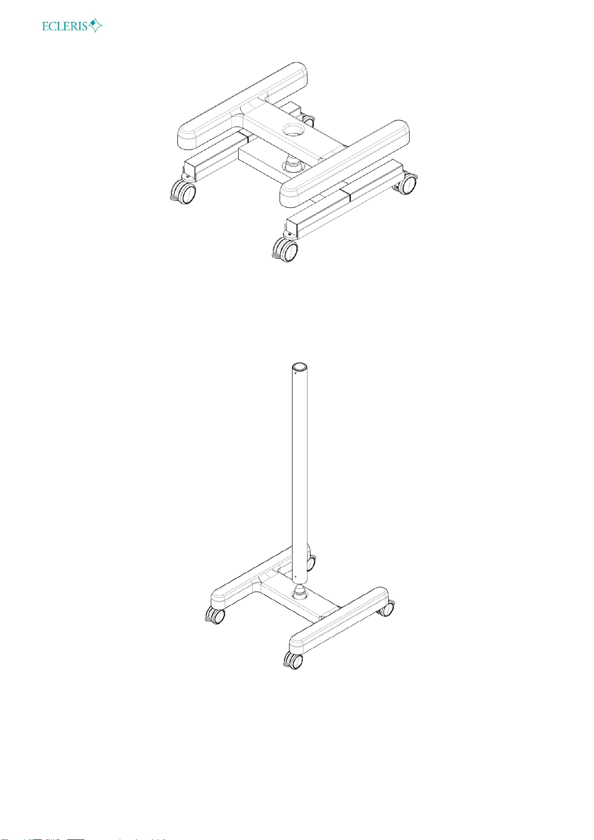
4.1 BASE INSTALLATION..........................................................................................................9
4.2 COLUMN INSTALLATION..................................................................................................10
4.3 FOREARM-COLUMN INSTALLATION...............................................................................11
4.4 OPTICAL HEAD-ARM INSTALLATION..............................................................................12
4.5 BINOCULAR-SPLITTER INSTALLATION ..........................................................................13
4.6 VIDEO CABLES INSTALLATION.......................................................................................15
5. OPERATION - FUNCTIONS..................................................................................................16
5.1 MICROSCOPE OPERATION.............................................................................................16
5.2 CONNECTIONS.................................................................................................................17
5.2.1 FOREARM ..................................................................................................................17
5.2.2 ARM............................................................................................................................17
5.3 LIGHT SOURCE.................................................................................................................18
5.4 INTERPUPILLARY DISTANCE ADJUSTMENT..................................................................18
5.5 DIOPTRIC CORRECTION ADJUSTMENT.........................................................................18
5.6 MAGNIFICATION VARIATION...........................................................................................19
5.7 COLOR FILTER SELECTOR .............................................................................................19
5.8 DIAPHRAGM SELECTOR..................................................................................................19
6. MOVEMENT AND SHIPPING................................................................................................19
6.1 FOREARM MOVEMENT....................................................................................................20
6.2 PANTOGRAPHIC ARM MOVEMENT.................................................................................20
6.3 ROTATIONAL MOVEMENT OF THE OPTICAL HEAD ......................................................21
6.4 OPTICAL HEAD ROTATION AXIS.....................................................................................22
6.5 OPTICAL HEAD TILT.........................................................................................................22
6.6 MICROSCOPE SHIPMENT................................................................................................23
6.7 MOUNTING THE MONITOR HOLDER...............................................................................23
7. MAINTENANCE.....................................................................................................................26
7.1 CLEANING.........................................................................................................................26

USER MANUAL / MANUAL DE USUARIO –MICROSTAR
Page 3of 64
INMANUUML019 USER MANUAL - M. USO OM-200 V.2023.01 ENG-ESP US
7.1.1 CLEANING THE EXTERNAL SURFACES..................................................................26
7.1.2 DISINFECTION...........................................................................................................26
7.1.3 CLEANING OF OBJECTIVE LENS AND EYEPIECES................................................26
7.2 ELECTRICAL CONNECTIONS..........................................................................................27
7.3 FUSE CHANGE..................................................................................................................27
8. TECHNICAL SPECIFICATIONS............................................................................................28
9. TROUBLESHOOTING...........................................................................................................31
10. TECHNICAL SERVICE.......................................................................................................32
11. WARRANTY.......................................................................................................................32

USER MANUAL / MANUAL DE USUARIO –MICROSTAR
Page 4of 64
INMANUUML019 USER MANUAL - M. USO OM-200 V.2023.01 ENG-ESP US
1. SYMBOLS
Warning
EU Authorized
Representative
Caution
CE Mark
Read the related documentation
This side up
Alternate current
Fuse
Protective earth (Ground)
Video output
Equipotential bonding
Freeze image function
Manufacturer identification
(Name, Address)
Video camera
Serial number
White balance function
Manufacturing date (MM/AAAA)
Lightning
Do not discard with the
household waste
Iris diaphragm
Light intensity
Temperature limits
Optical filter
Pressure limits
Fragile
Humidity limits
On/off integrated light
Keep away from rain
Decrease light intensity
Increase light intensity

USER MANUAL / MANUAL DE USUARIO –MICROSTAR
Page 5of 64
INMANUUML019 USER MANUAL - M. USO OM-200 V.2023.01 ENG-ESP US
2. SAFETY INFORMATION
This manual is intended to explain the installation and functioning of the device.
Warnings: This symbol shall be used in the manual to indicate situations of neglect which
could cause injuries or material considerable damage.
Cautions: This symbol shall be used in the manual to indicate information about
important cautions to prevent undesired consequences.
Read this manual carefully before using the device.
Should you have any doubt regarding the contents of the manual herein, or the operation and
safety of the device, contact your local distributor or the nearest ECLERIS office.
2.1 WARNINGS
It is important to read this manual carefully before using the Microstar Microscope.
ECLERIS will not be held responsible for damage that can occur to the device due to not
following the instructions or not observing the following criteria:
To avoid risk of electric shock, this device must only be connected to an earth-protected
power supply.
Do not install the equipment next to heat sources, such as heaters.
The Microscope must be used in medical facilities with a proper electrical installation,
including a grounding in compliance with the regulations.
The microscope should be connected to the mains through the supplied cord or a
replacement with the same certifications.
The mains should be grounded with no adapter needed.
The sectioning of the electrical network is carried out by disconnecting the power cable, or
by removing the connector from the electrical outlet.
The device is connected to a ground protection through a ground conductor in the power
supply cable. This ground connection is essential for the safe use of the equipment
The device is provided with a connectable power cable that assures proper electrical
isolation. If it needs to be replaced, it should have the same features than the original.
Only connect the device to visualization devices that meet the IEC 60601-1 standard.
Device not appropriate to be used near or around flammable anesthetic gas mixture with air,
oxygen or nitrous oxide.
Do not look directly into the light output; the optical head has a very bright light output.
To move the microscope (during installation and intended use) verify light is off, in order to
avoid bright light on the face.
Do not insert objects into the holes. Do not place any container with liquids on top of the
device.
In case of interference with other electro-medical or electric equipment, it is recommended
increasing the distance between the device and the other equipment to minimize these
effects.

USER MANUAL / MANUAL DE USUARIO –MICROSTAR
Page 6of 64
INMANUUML019 USER MANUAL - M. USO OM-200 V.2023.01 ENG-ESP US
Do not open the device. Maintenance and repairs must be done by ECLERIS or an
authorized company by the fabricant. ECLERIS will not be responsible for the
consequences of repairs or maintenance carried out by unauthorized personnel.
This instruction manual must be kept together with the equipment for future reference. In
case the device is sold or donated, this manual must be enclosed.
If by any of the following:
Inadequate use of the equipment.
Failure to use the instruction manual.
Bad maintenance and care of the equipment.
Repair or manipulation by unauthorized personal.
…personal or material damage is produced to a third party, ECLERIS, the manufacturer and
sales agent of this equipment, will not assume responsibility for said damage.
The device and its accessories should never be discarded with the household
waste. Please check local regulations for electronic components disposal or recycle
of electrical and electronic device.
3. DESCRIPTION
3.1 INTENDED USE
The microscope has been designed to perform observation in diagnostic and surgical procedures.
It is used in different medical specialties, as well as in dentistry, where a magnification of the
working field is necessary to ensure the success of the treatment.
3.2 INTENDED USER
The intended users of this device are physicians or other health professionals, with experience or
training in the use of microscopes.
3.3 DESCRIPTION AND COMPONENTS
The Ecleris Microstar OM-200 Microscope and its accessories allow this equipment to meet all
the necessary characteristics for the different specialties.
This user manual describes the recommended procedures in order to install and use the Ecleris
Microstar OM-200 Microscope. The user manual contains all the information about care and
properly handling of the microscope.
Read the manual thoroughly before operating the equipment.
The accessories of the Ecleris Microstar OM-20 Microscope are the following:
Monitor holder
Splitter
Special cable containing 1 male HDMI plug to connect to the video system, and 2 DC-
PLUG to power the splitter and the integrated light.
The device has different versions:

USER MANUAL / MANUAL DE USUARIO –MICROSTAR
Page 7of 64
INMANUUML019 USER MANUAL - M. USO OM-200 V.2023.01 ENG-ESP US
Code
Description
Binocular rotation
Pantographic arm
length
OM-200F
Floor-stand
Straight
23.03” (585mm)
45º Inclined
32,09” (815mm)
180° Inclinable
3.3.1 FLOOR STAND MICROSCOPE (OM-200F)
Components:
1. Optical Head
2. HD beam Splitter
3. Binocular
4. Tension knob
5. Progressive brake
6. Lock brake
7. Pantographic arm
compensator
8. Switch on/off
9. Forearm

USER MANUAL / MANUAL DE USUARIO –MICROSTAR
Page 8of 64
INMANUUML019 USER MANUAL - M. USO OM-200 V.2023.01 ENG-ESP US
10. Progressive brake
11. Progressive brake 12. Column
13. Microscope Base
3.3.2 OPTICAL HEAD
1. Magnification selector
2. Micro focus adjustment
3. Light filter selector
4. Diaphragm selector
5. Light on/off
6. Light intensity (increase)
7. Light intensity (decrease)

USER MANUAL / MANUAL DE USUARIO –MICROSTAR
Page 9of 64
INMANUUML019 USER MANUAL - M. USO OM-200 V.2023.01 ENG-ESP US
4. INSTALLATION AND OPERATION
4.1 BASE INSTALLATION
To assemble the microscope base, 4 wheels and 4 counterweights must be fitted.
The wheels are assembled by screwing the bolt into the ends of the base as indicated in the
following figure.
A wrench should be used to tighten the wheel bolts solidly to the base of the microscope.
The base has 4 removable weights that allow the easy handling of the microscope with a reduced
weight of the base.
Once the wheels have been mounted, the 4 removable weights must be placed.
Once the weights have been mounted, the plastic base cover must be placed on the base, as
indicated in the following figure:

USER MANUAL / MANUAL DE USUARIO –MICROSTAR
Page 10 of 64
INMANUUML019 USER MANUAL - M. USO OM-200 V.2023.01 ENG-ESP US
4.2 COLUMN INSTALLATION
Once the wheels and the base cover are placed, the column must be mounted on the base.
Put the column in the central axis of the base as indicated in the following figure:
Tighten the set screw with an Allen wrench.

USER MANUAL / MANUAL DE USUARIO –MICROSTAR
Page 11 of 64
INMANUUML019 USER MANUAL - M. USO OM-200 V.2023.01 ENG-ESP US
The column has to be mounted in the right position, as indicated in the following figure:
Column Top Column Bottom
4.3 FOREARM-COLUMN INSTALLATION
Place the forearm on top of the column, then tighten the screw in order to solidly attach the
forearm to the column.

USER MANUAL / MANUAL DE USUARIO –MICROSTAR
Page 12 of 64
INMANUUML019 USER MANUAL - M. USO OM-200 V.2023.01 ENG-ESP US
4.4 OPTICAL HEAD-ARM INSTALLATION
The optical head is mounted to the arm through a joint elbow of 60º, as shown in the picture
below.
Embellishing screw (E)
Tensor screw (D)
Clamping screw (C)
Fine washer (B)
Thick washer (A)
Security screw (F)
60º joint elbow

USER MANUAL / MANUAL DE USUARIO –MICROSTAR
Page 13 of 64
INMANUUML019 USER MANUAL - M. USO OM-200 V.2023.01 ENG-ESP US
Place the thick washer (A) on the 60º joint elbow. Then install the elbow on the microscope arm.
Continue placing the fine washer (B) on the arm, as the previous picture. Above it place the
clamping screw (C) and adjust it the maximum. Once it is completely adjusted, dis-adjust it half
turn.
Place the tensor screw (D) and adjusted to the maximum using a corresponding Allen key, as the
following picture.
Then place the embellishing screw (E) on top and adjust it completely. Finally adjust the security
(F) to the maximum.
It is important to adjust the optical head to the arm exactly according to the instructios
on this section, in order to stabelly install the device and prevent damage.
4.5 BINOCULAR-SPLITTER INSTALLATION
Either a binocular and a splitter, or just a binocular can be mounted on the upper side of the
Optical head.
Tensor screw (D)
Embellishing screw (E)
Security
screw (F)

USER MANUAL / MANUAL DE USUARIO –MICROSTAR
Page 14 of 64
INMANUUML019 USER MANUAL - M. USO OM-200 V.2023.01 ENG-ESP US
In case of installing the binocular, the maneuver must be performed by releasing the Optical head
adjustment screw, so that the binocular is inserted centrally in the upper part of the head. After
the joint is centered and flat against the Optical head, press the adjustment screw so that the
binocular remains firmly attached to the head.
If the microscope has a splitter, mount it on the Optical head, and then mount the binocular. In
both cases the adjustment screw must be released to engage the parts. Then use the same
screw as the adjustment mechanism.

USER MANUAL / MANUAL DE USUARIO –MICROSTAR
Page 15 of 64
INMANUUML019 USER MANUAL - M. USO OM-200 V.2023.01 ENG-ESP US
4.6 VIDEO CABLES INSTALLATION
The splitter and the Optical head with integrated light have specific power and video connectors
for normal operation. Once the splitter is mounted to the optical head, proceed to connect the
video and power cables.
The pack of cables contains 1 HDMI male plug to connect to the splitter, and 2 DC-PLUG to
power the splitter and the integrated light source. One of the power cables is slightly longer; this
one must be connected to the lighting system.
Once the HDMI cable is connected, it should be secured by the adjustment screws in order to
avoid damage of the HDMI connection of the splitter, caused by the tension of the Optical head
movement.
Using the microscope without the HDMI connector retaining screws could cause
premature deterioration of the splitter.
The other end of the video and power cable should be installed in the junction box of the arm.
Remove the fixing screws of the plastic cable cover in order to access the connections. Once the
video and power cables are connected, cover them with the plastic piece and secure it with the
fixing screws.

USER MANUAL / MANUAL DE USUARIO –MICROSTAR
Page 16 of 64
INMANUUML019 USER MANUAL - M. USO OM-200 V.2023.01 ENG-ESP US
5. OPERATION - FUNCTIONS
5.1 MICROSCOPE OPERATION
This section describes the equipment functioning procedure.
The device shall only be operated by personnel trained in the use of this type of
microscopes.
1) Connect the power supply cable to the microscope and then to the mains.
2) Press the power switch on the forearm to turn the unit on (the green indicator light will turn
on). The light source turns on automatically.
3) If the microscope arm is at its maximum height, the illuminator turns off to keep the equipment
in stand-by position. When the arm descends, the illuminator turns on automatically.
4) Press the on/off switch on the Optical head to turn off the light source.
5) Turn off the on/off switch (outward position).

USER MANUAL / MANUAL DE USUARIO –MICROSTAR
Page 17 of 64
INMANUUML019 USER MANUAL - M. USO OM-200 V.2023.01 ENG-ESP US
5.2 CONNECTIONS
A display monitor can be connected to the HDMI output located inside the Microstar Microscope
forearm. The forearm cover must be removed to access the connectors.
5.2.1 FOREARM
1. 100 VA auxiliary power
output (monitor
connection)
2. Power cord connector
100-240 V
3. HDMI output (monitor
connection)
The power consumption of the auxiliary power supply output must not exceed what is
indicated on the label.
5.2.2 ARM
If a splitter is installed, it will be connected to the HDMI output. The HDMI output is located in the
Microstar Microscope arm.
1. DC Plug 12Vcc
2. USB 5V-2,4A
3. HDMI (Splitter
connection)
1
2
3
1
3
2

USER MANUAL / MANUAL DE USUARIO –MICROSTAR
Page 18 of 64
INMANUUML019 USER MANUAL - M. USO OM-200 V.2023.01 ENG-ESP US
5.3 LIGHT SOURCE
The Ecleris Microstar OM-200 Microscope has a light module integrated to the microscope’s
Optical head. From this module you can turn the light on or off, vary its intensity, select different
diaphragm levels to reduce the illuminated field and select different light filters.
Switch on / off integrated light
Increase light intensity
Decrease light intensity
Diaphragm selector
Light filter selector (Neutral / Green / Orange / Deep orange)
Magnification selector
Micro focus
The integrated light system has a ventilation system. Do not obstruct air circulation.
The integrated light system generates running temperatures above room temperature.
This generation of heat is normal.
5.4 INTERPUPILLARY DISTANCE ADJUSTMENT
To perform this adjustment you must hold the body of the binocular with both hands and turn them
simultaneously. Move these backwards and forwards until the distance between the oculars
matches your interpupillary distance. The interpupillary distance can be manually adjusted
between 55 and 75 mm.

USER MANUAL / MANUAL DE USUARIO –MICROSTAR
Page 19 of 64
INMANUUML019 USER MANUAL - M. USO OM-200 V.2023.01 ENG-ESP US
5.5 DIOPTRIC CORRECTION ADJUSTMENT
The Ecleris Microstar OM-200 Microscope has independent dioptric correction for both eyepieces.
The adjustment is made by turning the eyepieces towards the + sign or towards the –sign.
5.6 MAGNIFICATION VARIATION
The magnification selector has six positions: 4/6/10/16/25x. The 10x position is repeated in the
selector. The mark on the Optical head (red dot adjacent to the magnification selector) will show
the selected magnification.
The microscope’s magnification can be changed with any of the commands located on either side
of the binocular, turning them slowly until the desired magnification level is reached.
5.7 COLOR FILTER SELECTOR
The microscope has 3 incorporated color filters. By turning the filter change knob, you can select
between green, orange, deep orange, or no color filter.
5.8 DIAPHRAGM SELECTOR
The microscope has a diaphragm selector to control the illumination. The diaphragm is
mechanical and manual with 8 levels of adjustment.
6. MOVEMENT AND SHIPPING
For the floor-stand setting microscope (OM-200F) it is mounted on 4-wheel-base with
independent brakes for each wheel. These allow an easy transport of the device to locate the
best required working position.
The microscope has joints and movements to set the optimum work position.

USER MANUAL / MANUAL DE USUARIO –MICROSTAR
Page 20 of 64
INMANUUML019 USER MANUAL - M. USO OM-200 V.2023.01 ENG-ESP US
6.1 FOREARM MOVEMENT
The forearm has a rotation system related to the column axis that allow its rotation to reach an
optimum work position. The forearm can rotate 320° related to the column axis, and it has stops
to avoid the accumulation of turns and winding of the cables.
6.2 PANTOGRAPH ARM MOVEMENT
The Pantographic arm can rotate 320° in relation to the forearm.
The correct vertical positioning of the microscope will be achieved by the articulated arm. It has
been designed and calibrated to achieve auto stability in the desired position with a minimum
effort. The Pantographic arm has an auto compensation system (WBS –Weight Balance System)
for weights between 3 and 7 kg. This system allows the movement adjustment according to the
number of installed accessories.
The lock brake of the arm must be loosen to balance the Pantographic arm weight. Place the arm
at horizontal position (halfway between minimum and maximum height) and adjust or loosen the
compensation system, with an Allen key, in order to balance the accessories’ weight. The system
is balanced when the arm position does not vary.
This manual suits for next models
2
Table of contents
Languages:
Other Ecleris Microscope manuals
Popular Microscope manuals by other brands

Andonstar
Andonstar A1 User introduction manual

Optilia
Optilia Flexia Definition HM ESD instruction manual

LW Scientific
LW Scientific LW-101 Specifications

BestScope
BestScope BS-2020B instruction manual

Bresser
Bresser NATIONAL GEOGRAPHIC 9118300 operating instructions

LABSTAC
LABSTAC MSC21-07 Operation manual