Vanguard 1400FLi Series User manual

Operation Manual
1400FLi Series
Covering Models:
1482FLi & 1486FLi

2
Introduction
Thank you for purchasing this VanGuard Microscope. With the user in mind, VanGuard Microscopes are built from modern
designs and should provide a lifetime of reliable performance. We recommend you read this entire manual carefully before
setting up and using the instrument.
The 1400FLi Series innity corrected uorescence microscopes
are the agship of the Vanguard microscope line. Combining
top performance with highly-advanced features and optics, the
1400FLi Series models produce uorescence images of the
utmost in clarity. Choose from brighteld or phase contrast/
brighteld/darkeld.
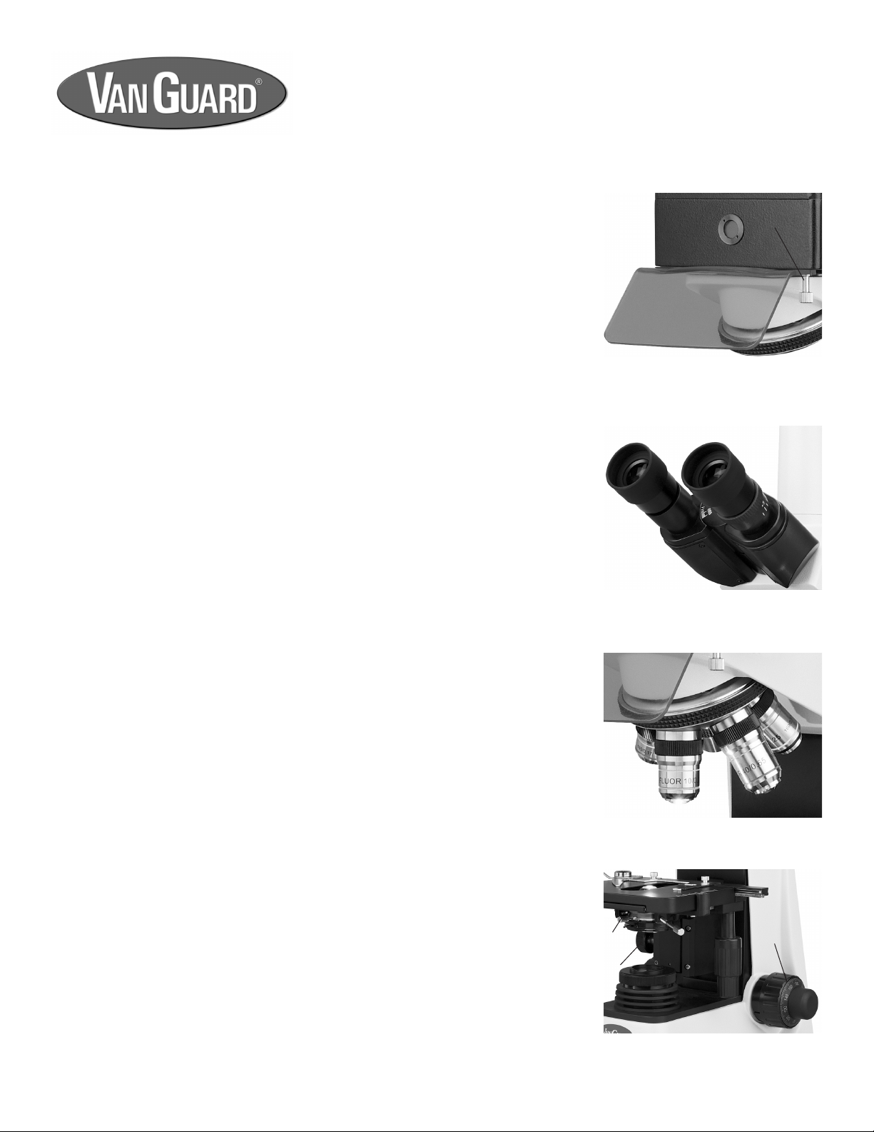
Viewing Head. Trinocular (Seidentopf) heads rotate 360° and are
inclined at 30°. Both models feature interpupillary and dioptric
adjustment. The heads feature a sliding main prism (70/30 split) to
provide full-time imaging when the vertical tube is in use.
Eyepieces. 10X high eyepoint, wideeld with an 18.5mm eld of view.
Nosepiece. Quintuple, reversed, ball-bearing nosepiece with high-
grade lubricant and positive stops. The nosepiece is reversed
(inward-facing) to allow for easier manipulation of slides and to aid
in keeping the objectives clean.
Objectives. Plan achromatic, uorescence objectives come standard
on both models. Model 1482FLi features plan achromatic brighteld
objectives. Model 1486FLi features plan achromatic phase contrast
objectives. All objectives are innity corrected and are light-reective
coated.
Stage. Delivering a high level of uid motion control and longevity,
the stage measures 160mm x 140mm, and features a removable
spring-clip slide holder and a chemical-resistant nish. Motion is
controlled by a right-hand, low-position coaxial control and is driven
by a rack and pinion system.
Focusing Movement. Coaxial, ultra low-position coarse and ne
focus controls feature a 40mm focusing range and are graduated
to 2 microns per division. Fitted with tension adjustment and safety
autostop.
Condenser. Model 1482FLi comes with a 1.25 N.A. Abbe Condenser.
Model 1486FLi comes with a 1.25 N.A. Zernike condenser with phase
annulus rings for 10X/20X, 40X and 100X; also has brighteld and
darkeld stops. All condensers are mounted on a rack and pinion
focusing mechanism and feature spring-loaded centering knobs and
an iris diaphragm.
Lower Illumination. 20W variable quartz halogen light source.
Comes with blue, green (model 1486FLi only), and dispersion lters.
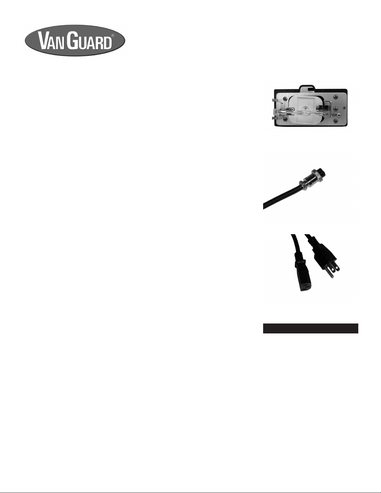
Upper Illumination. Features a 100W HBO mercury light source
mounted to the rear of the microscope and protected by a sturdy,
all-metal housing. The lamp is easily focused and centered with the
front-mounted lamp viewer. External power supply provides constant,
even light and features an electronic timer which automatically logs
the amount of time the mercury lamp is in use.
Fluorescence Filters. Features a 3-position (2 lter positions and 1
OFF position), sliding lter cube assembly. Fluorescence models come
standard with 2 broadcast lters (blue & green). Custom uorescence
lters available (contact us or your dealer for more details).
Base. Stable 225mm x 160mm base tted with anti-skid rubber feet.
Body. Cast-metal ergonomic body with stain-resistant enamel nish.
1400FLi Series Fluorescence Microscopes
Table of Contents
Introduction:....................................................... 2
Parts & Accessories
Included Parts:.................................................... 3
Optional Accessories:......................................... 4
Microscope Diagrams:........................................ 5
Setup
Assembly:......................................................... 7
Aligning the Condenser:....................................... 11
Alignment of Mercury Lamp............................... 10
Aligning the Phase Contrast Annulus Rings...... 12
Using your 1400FLi Series Microscope
Focusing & Mechanical Stage Mechanisms:...... 13
Setting the Up-Stop Mechanism.................... 13
Interpupillary & Diopter Adjustments:................. 14
Oil Immersion Objectives:................................... 14
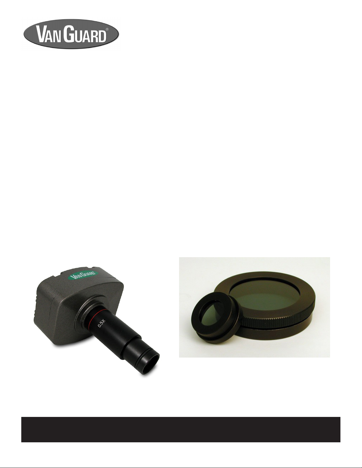
Using the Camera Port:..................................... 15
External Power Supply........................................ 16
Replacing the Power Supply Fuse..................... 16
Fluorescence Viewing........................................ 17
Maintenance
Replacing the Lower Lamp:............................... 18
Replacing the Microscope Fuse:........................ 18
Replacement Light Bulb/Fuse Information:........ 18
Specications:.................................................. 19
Warranty:............................................................ 20
See warranty details on page 20 for more information.
Warranty card available at:
www.veegee.com/pages/technical-support-service

Parts & Accessories
Included Parts:
Model 1482FLi
Trinocular Head (1 ea.)
Stand (1 ea.)
Brighteld Condenser (1 ea.)
Epi-Illumination Assembly (1 ea.)
External Power Supply (1 ea.)
10X High Eyepoint Eyepieces (2 ea.)
4X Innity Corrected, UV Pass Plan Objective (1 ea.)
10X Innity Corrected, UV Pass Plan Objective (1 ea.)
40X Innity Corrected, UV Pass Plan Objective (1 ea.)
100X Innity Corrected, UV Pass Plan Objective (1 ea.)
UV Shield (1 ea.)
Neutral Filter (1 ea.)
Blue Filter (1 ea.)
External Power Supply Cable (1 ea.)
Power Cord (2 ea.)
100W Mercury Lamp (1 ea.)
Spare 20W Halogen Lamp (1 ea.)
Spare Fuse, 0.25A, 250V (2 ea.) [Microscope]
Spare Fuse, 8A, 250V (2 ea.) [External Power Supply]
Eyecups (2 ea.)
Tension Wrench (1 ea.)
Dust Cover (1 ea.)
Instruction Manual (1 ea.)
Model 1486FLi
Trinocular Head (1 ea.)
Stand (1 ea.)
Phase Contrast/Brighteld/Darkeld Condenser (1 ea.)
Phase Contrast Centering Telescope (1 ea.)
Epi-Illumination Assembly (1 ea.)
External Power Supply (1 ea.)
10X High Eyepoint Eyepieces (2 ea.)
10X Plan Phase Objective (1 ea.)
20X Plan Phase Objective (1 ea.)
40X Plan Phase Objective (1 ea.)
100X Plan Phase Objective (1 ea.)
4X Innity Corrected, UV Pass Plan Objective (1 ea.)
10X Innity Corrected, UV Pass Plan Objective (1 ea.)
40X Innity Corrected, UV Pass Plan Objective (1 ea.)
100X Innity Corrected, UV Pass Plan Objective (1 ea.)
UV Shield (1 ea.)
100W Mercury Lamp (1 ea.)
Halogen Lamp (1 ea.)
Neutral Filter (1 ea.)
Blue Filter (1 ea.)
Green Filter (1 ea.)
External Power Supply Cable (1 ea.)
Power Cord (2 ea.)
Spare Fuse, 0.25A, 250V (2 ea.) [Microscope]
Spare Fuse, 8A, 250V (2 ea.) [External Power Supply]
Eyecups (2 ea.)
Tension Wrench (1 ea.)
Dust Cover (1 ea.)
Instruction Manual (1 ea.)
3

4
Parts & Accessories
For information about parts, accessories, or service -- contact your dealer directly or contact
VanGuard Microscopes at 1-800-423-8842.
Digital Camera Systems:
Part Number: Description:
1400-CDPC-10 USB Color Digital Camera System, 10 Megapixels
1400-CDPC-5 USB Color Digital Camera System, 5 Megapixels
1400-CDPC-3 USB Color Digital Camera System, 3 Megapixels
Other Accessories:
Part Number: Description:
Call for Part Numbers Scale Reticle
Call for Part Numbers Stage Micrometer
Call for Part Numbers Eyepieces (15X, 20X)
Call for Part Numbers Objectives: Plan Achromatic, Brighteld: 4X, 10X, 20X, 40X, 50X, 60X, 100X (oil)
Plan Achromatic, Phase: 10X, 20X, 40X, 100X (oil)
1200-IOG Immersion Oil, Low Viscosity (1/4 oz. Bottle)
Call for Details Custom Fluorescence Filters
Optional Accessories:

1400FLi Series Parts
5
Eyepieces with
Rubber Eyecups
Nosepiece
Objectives
Condenser
Coarse Focus
Control
Substage
Illuminator
Base
Slide Holder
X-Y Mechanical
Stage Controls
Head Set
Screw
(lower)
Camera Port
Mechanical Stage
Head Assembly
Focusing Tension
Control Knob
Prism Slider
Camera Port
Dust Cap
Iris Diaphragm
Adjustment Lever
Substage
Adjustment
Knob
Diopter
Adjustment
Mechanism
Interpupillary
Adjustment
Mechanism
UV Shield Set Screw
Mercury Lamp
Centering Window
Horizon-
tal Lamp
Centering
Knob
Vertical
Lamp
Centering
Knob
Lamp Door
Set Knob
Epi-Illuminator
Housing
Head Set
Screw (upper)
Lamp Focusing
Knob
Illumination
Tube Slider
Fluorescence
Filter Slider
UV Shield Lamp
Access
Door
Phase Annulus Turret
(1486FLi only)
Condenser Centering
Knobs
Stand
Slide Holder Knobs
Fine Focus
Control
Field Iris
Diaphragm
Model 1486FLi Shown
Lamp
Focusing
Set Screw
Annulus Center-
ing Knob (right)
Colored Filter Holder

6
Pictures and descriptions of the external power supply are shown on page 16.
Power Switch
Variable
Lighting
Control
Up-Stop
Mechanism
1400FLi Series Base, Left Side View
Substage
Adjustment
Knob
Power Cord
Jack
1400FLi Series Stand, Rear View
Carrying
Handle
1400FLi Series Parts

7
Setup
Assembly
Figure 1
Figure 2
1. After removing the microscope parts from the protective foam packaging and
checking it over for all components and accessories (a list is provided on page 3),
you can begin assembly.
2. Place the stand on a stable counter top.
3. Place the epi-illuminator housing assembly on top of the stand so that the dovetail
ange slides into place. Secure with the head set screw (see gure 1a).
NOTE: Do not release the epi-illuminator housing assembly until it is rmly
secured with the head set screw.
Figure 3
4. Place the head assembly on top of the epi-illuminator housing assembly so that the
dovetail ange slides into place. Secure with the knurled head set screw (upper)
(see gure 2a).
NOTE: Do not release the head until it is rmly secured with the head set screw
(upper).
NOTE: The head may be installed directly on the stand if the epi-uorescence
illuminator will not be used.
5. Remove the packing cap from the microscope head trinocular port and attach the
camera port to the head assembly by turning in a clockwise direction until tight
(see gure 3a).
The next 4 pages are dedicated to assembling a working microscope. The following section, “Using your 1400FLi Series
Microscope” (starting on page 13) explains the various features of the microscope and how to use them.
[a]
[a]
[a]
All Models

8
6. Attach the UV shield to the bottom front of the epi-illuminator housing assembly
with the UV shield set screw (see gure 4a).
Setup
7. Slide the eyepieces into the eyetubes and attach eyecups (see gure 5).
8. After removing the objectives from their storage containers, individually install
each one into the nosepiece by twisting them clockwise into the threaded holes
of the nosepiece (see gure 6).
9. Raise the substage and stage to their maximum height. Raise the stage via the
coarse/ne focus controls (see gure 7a), and the substage using the substage
adjustment knob (see gure 7b).
10. Loosen the condenser set screw (see gure 7c) enough to allow the neck of the
condenser to slide through the silver ring.
The next 4 steps describe how to install the condenser. With most microscopes the
condenser comes pre-installed. If this is the case skip ahead to step 13.
Assembly (continued)
Figure 4
Figure 5
Figure 6
Figure 7
[a]
[a]
[b]
[c]

9
11. Slide the neck of the condenser up through the silver ring of the condenser mount
until it will go no further (see gure 8). Make sure that the text “NA 1.25” is facing
upward. If the condenser will not slide freely through the silver ring do not force,
simply wiggle the condenser while lightly pushing up. It may be necessary to
loosen the up-stop mechanism in order to gain sufcient substage clearance
(refer to the instructions on page 13).
12. Once the condenser assembly is in place, lower the substage via the substage
adjustment knob and tighten the condenser set screw.
Note: The brighteld condenser (model 1482FLi) is pictured, but the assembly
instructions are identical for the phase contrast condenser (1486FLi).
Setup
Assembly (continued)
13. Remove the epi-illuminator lamp bracket access door (see gure 9a) from the
epi-illuminator housing by loosening the lamp door setscrew (see gure 9b) at
the top of the lamp bracket access door (located on the right side of the housing).
Once loosened, lift the access door up and away from the housing.
14. The epi-illuminator lamp bracket is shipped with a protective, insulating blank
mounted in place of the lamp in the lamp-mounting sockets (see gure 10a). This
must be removed and replaced by a lamp to operate the unit. Loosen the two
lamp mounting screws and slide out the blank.
WARNING: DO NOT open the housing assembly while the illuminator is in opera-
tion or when it is connected to the power supply. When replacing, allow the lamp
to cool for an extended period of time.
15. A 100W HBO Mercury Lamp comes with the unit. Remove the lamp from its
protective packaging.
Figure 11
Figure 8
[a]
Figure 9
Figure 10
[a]
[b]
Note: Do not touch the glass bulb directly, as ngerprints can etch the quartz
housing which decreases the bulb’s life and performance. If contact is made with
the glass bulb, clean with rubbing alcohol and dry thoroughly.
16. The lamp is polarized (one end is larger than the other). Insert the large end through
the exible mounting socket, but do not tighten the set screw (see gure 11).

10
Setup
Assembly (continued)
1. Once the external power supply is on, move the illumination tube slider into the 2nd or 3rd “open” position. Move the
uorescence lter slider into the middle or “0” position.
2. Look into the mercury lamp centering window located just below the eyepieces. If the lamp is centered, a green ball,
slightly smaller in diameter than the viewing window can be observed. If not turn the vertical and horizontal lamp cen-
tering knobs, located on the right side of the epi-illuminator housing, until the green ball is centered. If you see a green
light in the viewing window, use the focusing lever to concentrate the light into a ball.
3. If the lamp cannot be centered, it may have been mounted too far off center. In this case, the lamp must be physically
moved in its mount. Turn off the external power supply and disconnect the power supply cable from the epi-illumina-
tor housing. ALLOW THE LAMP TO FULLY COOL.Open the lamp bracket access door and reposition the lamp as
needed, being careful not to touch the glass envelope of the lamp. Close the lamp bracket access door and reconnect
it to the external power supply with the power supply cable. Repeat the above procedures until the lamp is centered.
4. Once the lamp is centered and focused, these procedures do not have to be repeated until the lamp is replaced (unless
the settings are changed inadvertently).
Alignment of the Mercury Lamp
NOTE: Please see page 16 to familiarize yourself with the operation of the external power supply before turning
the external power supply on.
21. Plug the power supply cable (see gure 13) into the external power supply by lining
up the notch on the plug with the alignment lug located in the socket. Secure the
power supply cable by tightening the threaded silver ring.
22. Connect the female end of the rst power cord (see gure 14) to the rear of the
microscope, and the male end to a suitable power supply.
23. Connect the female end of the second power cord (see gure 14) to the rear of
the power supply, and the male end to a suitable power supply.
24. Turn the substage illuminator on with the power switch located on the lower left
side of the instrument. If the light does not come on, check to see that the variable
lighting control, located next to the power switch is on the highest setting.
17. When the large end is in the exible mounting socket, manipulate the exible
mounting socket to get the small end into the stationary mounting socket (see
gure 12).
18. Push the small end in as far as it will go and then tighten the set screw on the
stationary mounting socket.
19. Adjust the exible mounting socket so that the set screw is over the metal end of
the lamp, then tighten the set screw.
20. Place the entire assembly back inside the epi-illuminator housing and secure it
in place with the lamp door set screw. Make certain there are no gaps between
the lamp bracket access door and the epi-illuminator housing.
Figure 13
Figure 12
Figure 14
All Models

Setup
Note: If you purchased a 1482FLi this step completes the setup. Skip ahead to page 13, “Using Your 1400i Series
Microscope”.
11
Aligning the Condenser
Adjustments to the substage condensing system are crucial for proper illumination and performance. There are three basic
adjustments which need to be made: Centering, Vertical Focusing, and Aperture Adjustment.
Figure 15A Figure 15B Figure 15C Figure 15D
1. Centering: The condenser must be centered in the light path to ensure proper light control. A simple method for
centering is as follows:
Rotate the nosepiece until the 10X objective is in the light path.
Raise the substage assembly fully by turning the substage adjustment knob counter-clockwise.
Use the focus controls to focus on a specimen located on the stage.
Open the aperature iris diaphragm to the largest setting by using the aperature iris diaphragm adjustment lever
which extends from the condenser assembly.
While looking into the microscope eyepieces, close the eld iris diaphragm to the smallest setting by turning the
uppermost section of the substage illuminator counter-clockwise.
Closing the iris in this manner will reduce the eld so that a small white hexagon is visible within a black eld (see
gure 15A). Focusing of the hexagon is performed by turning the substage adjustment knob. This white hexagon is the
light which is passing through the eld iris and should be centered in the black eld. If not, move it to the center (see
gure 15B) by tightening and/or loosening the condenser centering knobs.
Fine tuning can be done by opening the eld iris diaphragm until the white hexagon almost lls the entire eld (see
gure 15C), and then readjusting (see gure 15D). After centering the condenser open the eld iris diaphragm slightly
wider than the eld of view.
If the iris isn’t centered in the eld of view then use the condenser centering knobs to adjust. You may have to split the
alignment difference between the eld iris and the condenser iris to achieve a balance.
2. Vertical Focusing: The condenser can be raised and lowered with the substage adjustment knob to focus the light for
optimal illumination.
3. Aperture Adjustment: The light path can be adjusted with the aperature iris diaphragm adjustment lever located just
below the condenser. Aperture adjustments are made to induce contrast into a specimen, not to adjust light intensity.
All Models

Setup
Note: This completes the setup for the 1486FLi. The next 5 pages will explain how to use and make adjustments
to the microscope.
12
1. Begin by turning on the substage illuminator with the power switch located on the
lower left side of the instrument. Set the objectives so they are in the approximate
position for actual use. This is best achieved by placing a slide on the stage,
rotating the 100X objective into position, then raising the stage (via the coarse/
ne focus control knobs) until the tip of the 100X objective is just above the slide
(almost touching).
2. Rotate the nosepiece until the 10X objective is in the light path, then rotate the
phase annulus turret (the dial on the front of the condenser) in the phase contrast
condenser assembly until the “10” is seen in the viewing window (see gure 16).
3. Remove an eyepiece from one of the eyetubes and replace with the phase contrast
centering telescope (see gure 17).
4. After loosening the set screw on the phase contrast centering telescope, look
through the phase contrast centering telescope and pull out the uppermost piece
of the phase contrast centering telescope until the image is in focus. Tighten the
set screw.
5. The image seen through the phase contrast centering telescope should resemble
rings superimposed on one another (see Figure 18A). What is actually being
viewed are the phase rings.
6. Turn the condenser centering knobs, which extend from the front of the condenser
mount, until the two rings of light are centered upon one another (see Figure 18B).
Aligning the Phase Contrast Annulus Rings
Phase contrast is a system which utilizes a series of light bafing annulus rings. Proper
alignment of these rings is absolutely necessary to achieve optimal phase contrast.
Figure 7BFigure 7A
1486FLi Model
Figure 17
Figure 16
7. Once the phase rings are centered, remove the phase contrast centering telescope and replace with the eyepiece.
The phase rings are now centered for the other remaining objectives unless one of the factory phase objectives has been
replaced. In this instance you will need to align just that condenser setting for your new objective using the centering knobs
located at the rear of the condenser (not the knobs at the front as used in step 6 above).
NOTE: Brighteld work can be achieved by setting the condenser at the “0” marking. Likewise, the “DF” setting is
for Darkeld work.

13
1. Focusing adjustment is achieved by turning the coarse/ne focus controls (see gures 19a and 20a). The large knob
is used for coarse adjustment, the smaller knob for ne adjustment. The coaxial arrangement allows for easy, precise
adjustment without stage drift.
2. Turning the coarse/ne focus control raises and lowers the stage vertically. One complete turn of the ne focusing knob
raises or lowers the stage 0.3mm; the smallest graduation refers to 2 microns of vertical movement. One complete turn
of the coarse focusing knob raises or lowers the stage 3.6mm. To ensure long life, turn the focusing knobs slowly and
uniformly.
3. The focusing tension control knob is located just inside of the right-hand focus control knob (see gure 19b). For tighter
tension, turn the control knob in a clockwise motion. For looser tension, turn the control knob in a counterclockwise
motion.
4. Vertical Focusing: The condenser can be raised and lowered with the substage adjustment knob (see gure 20b) to
focus the light for optimal illumination.
5. Aperture Adjustment: The light path can be adjusted with the iris diaphragm adjustment lever located underneath the
condenser. Aperture adjustments are made to induce contrast into a specimen, not to adjust light intensity.
Focusing and Mechanical Stage Mechanisms
The up-stop mechanism is located just inside of the left-hand focus control knob (see gure 20c). It allows the user to set a
maximum point to which the stage can be raised.
Setting the Up-Stop Mechanism
1. To set this point, turn the up-stop mechanism in a counterclockwise motion, so that its tab is facing up.
2. Raise or lower the stage, by turning the focus control knobs, to the desired height. Be careful not to raise the stage
high enough to crash into the objective.
3. Once achieved, turn the up-stop mechanism in a clockwise motion, so that its tab is facing forward.
4. Once gently tightened, the up-stop mechanism will not allow the stage to be raised higher than the set point.
Figure 19 Figure 20
Using your 1400FLi Series
Microscope
6. The mechanical stage X-Y controls, located underneath the right-hand side of the mechanical stage (see gure 19c),
provide easy and accurate positioning of the sample. One complete turn of the longitudinal (Y) control (lower half of the
stage controls) will move the specimen 34mm left or right. One complete turn of the transverse (X) control (upper half
of the stage controls) will move the specimen 20mm front or back.
7. The spring-loaded slide holder can be removed for users who prefer to not use a mechanical stage. Simply loosen the
knurled slide holder knobs which lock the slide holder on the stage, and slip out the slide holder.
[a]
[b]
[b]
[c]
[c]
All Models
All Models

14
1. Interpupillary adjustment (the distance between eyepieces) is made through a “folding” action. The Seidentopf design
allows for a folding adjustment which is quickly and easily done for each user (see gure 21).
2. Dioptric adjustment allows for proper optical correction based on each individual’s eyesight. This adjustment is easily
made and is recommended prior to each use by different users to prevent eyestrain.
3. Using the 40X objective and a sample slide (i.e. one which produces an easily focused image), close your right eye and
bring the image into focus in your left eye with the coarse/ne focus control. Once the image is well-focused using only
your left eye, close your left eye and check the focus with your right. If the image is not perfectly focused, make ne
adjustments with the diopter adjustment mechanism located on the right eyetube (see gure 22a). Once complete, the
microscope is corrected for your vision.
Interpupillary and Diopter Adjustments
The 100X objective which comes with this microscope must be used with immersion oil in order to maintain image quality.
After use, the objective tip must be wiped clean so that no oil residue remains.
Procedure for cleaning the 100X Oil Immersion Objective:
1. Lightly moisten a cotton swab with lens cleaner.
2. Wipe the objective with a twisting motion in order to remove all traces of the immersion oil.
3. Check that all the immersion oil has been removed before storing the objective.
Under no circumstances should an oil immersion objective be left sitting in oil for an extended period of time. Exceptionally
long immersion periods can cause oil to penetrate the objective’s sealant and obscure the optics, which is not covered under
warranty.
Oil Immersion Objectives
Using your 1400FLi Series
Microscope
Figure 22Figure 21
[a]
All Models
All Models

15
1. Make sure that you have installed the camera port tube as described on page 7 and shown
in gure 23.
2. Assemble the adapters and connect to the camera using the instructions provided with
the camera/adapter kit.
Note: Camera kit is not included with this microscope. Please see page 4 for available
camera kits.
Using the Camera Port
Using your 1400FLi Series
Microscope
Using Filters
Your VanGuard Microscope was supplied with either two or three colored lters depending
on model. Brighteld models come with a dispersion (frosted) lter and a blue lter. Phase
contrast models add a green lter.
Procedure for Using Filters:
1. Locate the drop-in lter holder (see gure 25a) located on the top of the substage illuminator.
2. Place the desired lter into the lter holder.
Dispersion lters can be used to soften harsh illumination for both viewing and photomicroscopy.
The green lter (provided with model 1486FLi) is used mainly for adding contrast and
photograph color correction during phase contrast work.
The blue lter is used to approximate natural light and photograph color correction.
Filtering is a user preference and application specic issue and therefore is beyond the
scope of this manual. There are many sources available that explain proper ltering
technique and theory.
All Models
Figure 23
Figure 24
3. Remove the camera port dust cap, then slide the adapter into the camera port (see gure
24).
4. Pull the prism slider completely out to divert the image to the camera port. The prism slider
is the silver knob on the right side of the head assembly (see gure 24).
Note: The 1400FLi Series Microscopes utilize a 70/30 split sliding prism. This split prism
diverts 70% of the light to the camera port and the remaining 30% to the eyepieces.
This allows the eyepieces to be used while the prism slider is pulled out, although the
image seen through the eyepieces will be dim when compared to normal use.
5. When the camera port is not in use, be sure to cover with the camera port dust cap.
Figure 25
[a]
All Models
All Models

16
WARNING: DO NOT attempt to operate the power supply unless the illuminator unit is connected
and has a 100W HBO Mercury lamp in place.
External Power Supply
1. Follow the instructions on page 10 to setup the external power supply.
Using your 1400FLi Series
Microscope
2. Activate the power supply by switching on the power switch located on the right side of the power supply face.
3. Allow 10 to 15 minutes for the mercury lamp to stabilize before viewing uorescence objects through the microscope.
4. The power supply is equipped with a timer to log the total time the mercury lamp is in use. The lamp should be replaced
after 100 hours of use. This is very critical for maintaining good illumination and to help prevent the lamp from bursting.
5. Follow the instructions on page 10 to replace the lamp.
NOTE: Allow the lamp to cool for an extended period of time before replacing.
6. After lamp replacement reset the timer by inserting a small pin (paperclip, etc.) into the reset hole located on the front
of the power supply face.
7. Although the lamp has a nite service life, it is recommended that it NOT be switched on and off frequently. Doing so
can shorten the life of the lamp and the power supply. Once the power supply is turned off, allow the unit to cool
down for at least 15 minutes before powering on again.
8. To turn off the power supply, move the power switch to the off position.
9. If the external power supply is plugged in but the lamp is not turning on, the fuse could be blown. To replace the fuse,
UNPLUG THE POWER SUPPLY, then unthread the fuse holders from the rear of the power supply.
10. If a fuse is blown (the wire inside is broken, or the glass is blackened), replace by inserting a new fuse into the fuse
holder, then thread the fuse holder back into the power supply by turning in a clockwise direction.
Counter Reset
Button
Illuminator
Box Power
Jack
Current Meter
Mercury Lamp
Timer
Cooling Fan
Main
Power Jack
Figure 26 Figure 27
Power
Switch
Fuse Holders
All Models

17
1. Select the desired magnication by choosing the appropriate objective. It is usually easiest to focus initially by using
brighteld or phase contrast.
2. For non-uorescence operations, it is not necessary to turn off the power supply. Instead move the illumination tube
slider into the 1st or “blocked” position.
3. Once the specimen is in place, switch to epi-illumination by moving the illumination tube slider into the 2nd or 3rd “open”
position. Select the appropriate lter cube by moving the uorescence lter slider into the “B” or “G” position. For the
blue lter, push the uorescence lter slider all the way to the left. For the green lter, pull the uorescence lter slider
all the way to the right. The “0” (off) position is located halfway between the blue and green lter cubes.
Position
B
G
Color
blue-green
green-red
Excitation
430-490nm
480-550nm
Emission
520nm
590nm
Intended Dyes
FITC, Acridine Orange
Ethidium Bromide, Propidium Iodide & TRITC
SAFETY WARNING
Fluorescence Viewing
Using your 1400FLi Series
Microscope
100W HBO Short-Arc Mercury Lamps
The supplied 100W HBO Short-Arc Mercury Lamps have a discharge vessel made of high optical quality quartz glass containing
mercury and a noble gas. The special characteristics of HBO lamps are extremely high luminance, strong ultraviolet radiation,
good luminous efcacy, and high arc stability.
UV Radiation and Glare
During operation, HBO lamps generate intensive radiation in the ultraviolet and visible range due to the high luminance of
the arc. When inadvertently touched, it should be degreased immediately with spirit and a soft, lint-free cloth. Afterwards,
gently wipe the quartz envelope until dry.
WARNING: Avoid prolonged exposure to unltered ultraviolet light.
HBO lamps should be replaced as soon as the bulb shows advanced blackening, otherwise the risk of the lamp bursting is
greatly increased. With normal operation, a lamp burst is very unlikely. In the rare case that an HBO lamp bursts and the
mercury is released, it is recommended that all personnel should leave the immediate area at once, so that no mercury
vapor is inhaled. The area should be thoroughly ventilated for a minimum of 30 minutes.
All Models
All Models
All Models

The eyepieces and objectives on VanGuard Microscopes are coated. They should never be
wiped while dry as any dirt or dust will scratch the coating. The surfaces should either be
blown off with an air canister, or blown and cleaned with an air-bulb and camel-hair brush.
It is recommended to then use a lens cleaner. Apply with a cotton swab for a minimum of
wetting, then wipe the surface clean with a quality lens tissue. Xylene, since it breaks down
the bonding material holding the lenses, should never be used as a cleaner. Periodically
your VanGuard Microscope should be fully serviced by a qualied service technician.
Maintenance
1. If the microscope is plugged in but the lamp is not turning on, the fuses could be blown.
To check the fuses, UNPLUG THE MICROSCOPE FROM YOUR POWER SOURCE
and remove the 5 screws securing the back panel (see gure 30).
2. Once the screws are removed, carefully pull the rear cover away from the microscope.
There is a small circuit board connected to the rear cover that houses the two fuses (see
gure 31 - note: connecting wires removed for clarity). Avoid pulling on the rear cover
hard enough to loosen any of the wires that connect the circuit board to the microscope.
3. To replace the blown fuse(s) (the wire inside is broken, or the glass is blackened) pull
the fuse out of it’s holder and snap a new fuse in. You might need to use a screwdriver
to lever the fuse out, but be careful not to scratch the circuit board.
4. Replace the rear cover and the ve screws.
Replacing the Microscope Fuse
1. Before attempting to replace or remove the lamp, UNPLUG THE MICROSCOPE FROM
ANY POWER SOURCE AND ALLOW SUFFICIENT TIME FOR THE LAMP TO COOL.
2. Lamp replacement is done by laying the microscope on its back and opening the trap
door located on the bottom of the base by pulling on the release knob (see gure 28).
Note: Be careful not to touch the glass lamp when replacing -- use a tissue or other
medium to grasp the lamp. This will prevent the oils from your hand from reducing
lamp life. If contact is made with the lamp, clean lamp with rubbing alcohol and allow
a brief drying period.
3. Once the door is open, the lamp can easily be removed simply by grasping the lamp
and pulling it from the xture (see gure 29).
4. When replacing, insert the new lamp into the same xture. Make sure that the pins on
the lamp slide easily into the slots. You should not have to force the lamp.
Replacing the Lower Lamp
Maintenance
Replacement Lamp (Lower) -- 20W Halogen (Part No. 1400-20WHL)
Replacement Lamp (Upper) -- 100W HBO Mercury (Part No. 1400-100WMLO)
Replacement Fuse (Microscope) -- 0.25A, 250V (Part No. 1400-FS1) [2 required]
Replacement Fuse (External Power Supply) -- 8A, 250V (Part No. 1400-FS4 ) [2 required]
18
Figure 28
Figure 29
Figure 30
Figure 31
For information about parts, accessories, or service -- contact your dealer directly or contact
VanGuard Microscopes at 1-800-423-8842.
Refer to page 16 (steps 9-10) for instructions on replacing the fuse in the external
power supply.
All Models
All Models
All Models

19
Specications
Viewing Head: Trinocular
Viewing Head Type: Seidentopf
Head Rotation: 360°
Head Inclination: 30°
Sliding Prism: 70/30 Split
Interpupillary Adjustment: 55-75mm
Dioptric Adjustment: -5 to +5
Eyepiece Magnication: 10X Wideeld, High Eyepoint
Eyepiece Field Diameter: 18.5mm
Nosepiece: Quintuple/Reversed
Fluorescence Objectives (All Models): 4X [0.10 N.A., 17.0mm W.D., 4.5mm F.O.V.]
Achromatic, Innity 10X [0.25 N.A., 8.0mm W.D., 1.8mm F.O.V.]
40X [0.65 N.A., 0.40mm W.D., 0.45mm F.O.V.]
100X [1.25 N.A., 0.25mm W.D., 0.18mm F.O.V.]
Brighteld Objectives (1482FLi): 4X [0.10 N.A., 17.0mm W.D., 4.5mm F.O.V.]
Plan Achromatic, Innity 10X [0.25 N.A., 8.0mm W.D., 1.8mm F.O.V.]
40X [0.65 N.A., 0.40mm W.D., 0.45mm F.O.V.]
100X [1.25 N.A., 0.25mm W.D., 0.18mm F.O.V.]
Phase Contrast Objectives (1486FLi): 10X [0.25 N.A., 8.0mm W.D., 1.8mm F.O.V.]
Plan Achromatic, Innity 20X [0.40 N.A., 0.50mm W.D., 0.9mm F.O.V.]
40X [0.65 N.A., 0.40mm W.D., 0.45mm F.O.V.]
100X [1.25 N.A., 0.25mm W.D., 0.18mm F.O.V.]
Fluorescence Filter Cubes: Blue Broadband [Dichroic: 500nm, Excitation: 430-490nm, Emmision 520nm]
Intended Dyes: FITC, Acridine Orange, & Auramine
Green Broadband [Dichroic: 570nm, Excitation: 480-550nm, Emmision: 590nm]
Intended Dyes: Ethidium Bromide, Propidium Iodide, & TRITC
Stage Dimensions: 160mm x 140mm
Stage Motion: Right-Hand Coaxial Control/Rack & Pinion Drive
Stage Movement Range: 50 x 75mm
Focusing Movement: Coaxial Coarse & Fine Controls/Safety Autostop
Focusing Range: 40mm
Focusing Graduation: 2 Microns/Division
Brighteld Condenser (1482FLi): 1.25 N.A. Abbe Condenser with Iris Diaphragm
Phase Contrast Condenser (1486FLi): 1.25 N.A. Zernike Condenser with Iris Diaphragm and Brighteld/Darkeld
Stops
Phase Centering Tool (1486FLi): Telescoping Eyepiece
Lower Illumination: 20W/6V Variable Quartz Halogen with Köhler Field Diaphragm
Upper Illumination: 100W HBO Mercury
Fuses: 0.25A, 250V (2 ea.) [Microscope]
8A, 250V (2 ea.) [External Power Supply]
Voltage: 110V
Base Dimensions: 225mm x 160mm
Overall Dimensions: 225mm (L) x 160mm (W) x 465mm (H)
Weight: 10.7kg
1400FLi Microscopes

20
Warranty & Service
VanGuard microscopes are warranted by VEE GEE Scientic LLC
to be free from defects in material and workmanship for a period
of ve (5) years from the date of purchase, except for electrical
components which have a one (1) year limited warranty. During
this period, VEE GEE Scientic, or its authorized service station,
will at their option and without charge, either repair or replace any
part found to be defective in materials or workmanship.
This warranty is subject to the following limitations and exceptions
and will not apply if:
1) There is lack of proof of date and place of purchase. The
purchase invoice must accompany the unit when sent in for repair.
The warranty extends to the original consumer purchaser only and
is not assignable or transferable.
2) The damage is due to normal wear and tear, misuse, abuse,
negligence, accident, inadequate maintenance, disregard
for operating instruction, or to any other cause not due to the
manufacture of the microscope (e.g., objective failure because of
oil penetration due to lack of timely cleaning).
3) The serial numbers, names, and/or functions are altered or
obliterated; or unauthorized repair or replacement of parts by the
End-User or an unauthorized third party while under warranty.
4) Consumable items (such as, but not limited to, bulbs) have failed.
This warranty expressly excludes transportation damage and
adjustment or readjustment. In no case shall VEE GEE Scientic
be liable to the Buyer or any person for any special, indirect,
incidental, or consequential damage whether claims are based
in contract or otherwise with respect to or arising out of product
furnished hereunder. For goods manufactured by any third party,
VEE GEE Scientic’s liability under warranty is limited to the terms
of the warranty by the supplier for the goods. All warranty work
shall be performed at the authorized service center. Contact your
distributor or VEE GEE Scientic to discuss the problem and obtain
instructions for the return of your microscope for repair. The original
purchaser returning this product must prepay all postage, shipping,
transportation, packaging, and delivery costs.
5 Year Limited Warranty
Contact Information:
Toll Free 800-423-8842
Email [email protected]
Web veegee.com
If you experience problems setting up your
microscope or have service related questions
please contact your dealer or VanGuard
Microscopes directly at 1-800-423-8842.
Our standard business hours are
7:00 a.m. - 5:00 p.m. Central Standard Time.
This manual suits for next models
2
Table of contents
Other Vanguard Microscope manuals

Vanguard
Vanguard 1210CM, 1211CM, 1220CM, 1221CM, 1222CM, 1223CM, 1230CM, 1231CM, 1232CM,... User manual

Vanguard
Vanguard 1320BR User manual

Vanguard
Vanguard 1200CM Series User manual

Vanguard
Vanguard 1400 Series User manual

Vanguard
Vanguard 1442MMi User manual

Vanguard
Vanguard 1400INi Series User manual

Vanguard
Vanguard 1109AML User manual

Vanguard
Vanguard 1241MM Installation manual

Vanguard
Vanguard 1111AML User manual