Eclipse Magnetics Micromag HP/50NPT User manual
Operating Instructions
Micromag HP/50NPT
High Intensity Magnetic Filter
Representative:
While every effort has been made to ensure the accuracy of the information in this publication please note that specifications may
change without notice.
Eclipse Tools North America Inc.
442 Millen Road, Unit #9, Stoney Creek, ON L8E 6H2
T1(800) 260-2124 F 1(800) 260-1410
[email protected] www.eclipsemagnetics.com/na
www.eclipsemagnetics.com/na
V3

3
1 Introduction
1.1 Range of application
The Micromag HP/50NPT follows on from the standard Micromag family and has all the same
incredible benets. The unit was developed to suit high pressure/temperature applications.
Micromag HP/50NPT can be installed anywhere in the uid delivery system and can remove
sub-micron magnetic and para-magnetic particles.
For further information relating to the standard benets and operation please refer to the
downloadable Micromag brochure on our website – www.eclipsemagnetics.com/na in
the ‘Magnetic Filtration’section.
The lter is not to be used with a corrosive or aggressive medium unless it is specied at the
time of order and the vessel is supplied with a suitable barrier coating i.e. PTFE.
Pressure rating – Standard lter is designed and tested to operate at 725 psi (50 bar) max.
line pressure.
DO NOT USE IN EXPLOSIVE ATMOSPHERE UNLESS
ORDERED AS AN ATEX APPROVED PRODUCT!
1.2 Used symbols
Important notes
Danger notes
Safety notes
Contents
1 Introduction
1.1 Range of application 3
1.2 Used symbols 3
1.3 Overview 4
2 Technical data
2.1 Performance data 5
2.2 Noise data sheet 5
3 Design and method of operation
3.1 Method of operation 6
3.2 Construction 6
4 Safety
4.1 Intended use 7
4.2 General preventive measures 7
4.3 Dangers of not adhering to safety notes 7
4.4 Safety notes for operation and maintenance 7
4.5 Notes on residual risks 8
4.6 Consequences with arbitrary change 8
4.7 Prohibited operation 8
5 Installation and use
5.1 Mechanical installation 9
5.2 Connections 9
5.3 Setting of the operating parameter 9
5.4 Cleaning 10
6 Maintenance
6.1 General notes 10
7 Spare parts/service
7.1 Spare parts list 11
7.2 Service address 11
8 Shipping, preservation, waste
disposal, transport, storage
8.1 Shipping, preservation, waste disposal 12
8.2 Transport 14
8.3 Storage 15
54
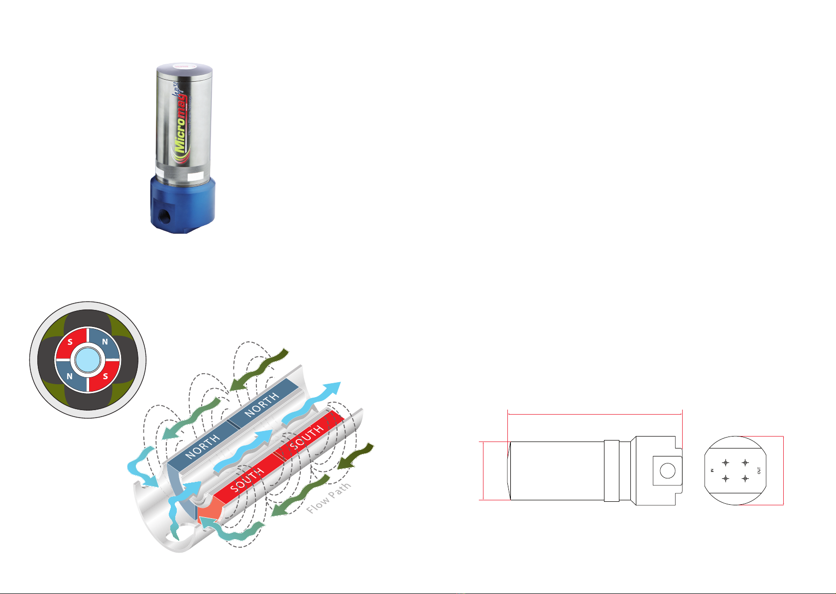
1.3 Overview
Details of magnetic circuits showing open ow path through bowl even when core is fully
contaminated.
2 Technical data
2.1 Performance data
Application ambient temperature: 32°F to 284°F (0°C to 140°C)
Design temperature: 302°F (150°C)
Operating design pressure: 725 psi (50 bar)
Throughput: MM5/HP/50NPT 18 gallons/minute
MM10/HP/50NPT 26 gallons/minute
MM20/HP/50NPT 40 gallons/minute
Vessel: Aluminium
Magnetic characteristics
max. operating temperature: NdFeB HT-material 302°F
Port size and contamination capacity
5”unit – 1”NPT 2.2 lbs capacity
10”unit – 1”NPT 4.4 lbs capacity
20”unit – 1 ½”NPT 8.8 lbs capacity
2.2 Noise data sheet
Sound pressure level, measurement according to DIN 45635:
Idling < 70 dB (A)
Conveying < 70 dB (A)
2.3 Dimensions
5”unit: A = 9.72 inches (247mm)
10”unit: A = 14.37 inches (365mm)
20”unit: A = 24.61 inches (625mm)
A
¯116 ¯138

76
3 Design and method of operation
3.1 Method of operation
The single magnetic core is integrated in an aluminium housing and forms one unit e.g. tted
in series with the pipe-line.
The ow is arranged in such a manner that the material that is to be cleaned is well
distributed and comes intimately into contact with the magnetic eld.
3.2 Construction
• All aluminium construction with optional internal coatings
• Viton‘O’ ring lid seals
• High intensity magnetic core
4 Safety
4.1 Intended use
The inline liquid lter is designed for installation into pressurised pipe lines working at up to
725 psi (50 bar). All pipeline connections are to be installed accurately and sealed to prevent
the loss of pressure/uid.
The lid seal is to be maintained in a good condition.
To ensure that the supplied magnets maintain their high level of performance, attention
must be paid to the following conditions:
1. NO temperatures above the specific operating temperature
2. NO oscillating vibrations
3. NO impacts
4. NO strong external magnetic flux fields
5. Pay attention to the cleaning and maintenance of the system
4.2 General preventive measures
The core is constructed with strong magnets. The handling of ferrous tools (e.g. with
maintenance or cleaning) etc. can cause risk of injury for the personnel due to the magnetic
attraction. Special measures regarding the presence of ferrous items have to be considered
when handling magnetic material.
4.3 Dangers of not adhering to safety notes
Using this equipment in a manner not intended can be hazardous.
4.4 Safety notes for operation and maintenance
Maintenance work is to be executed only by technical personnel. With work on pneumatic,
hydraulic, pressurised or electrical services, the supply lines are to be isolated prior to any
cleaning or maintenance actions.
Prior to any maintenance work being carried out, the process, equipment used and personnel
must be risk assessed and deemed suitable to conduct that task. All work is to be carried out
in accordance with local and legislative regulations.

98
WARNING! This system incorporates strong permanent magnetic materials.
Please pay attention to the safety notes in order to avoid personal injury or
material damage:
• Operators tted with a heart pace-maker shall not come within 1m of the equipment
• Oppositional poles of magnets attract each other with high clamping forces
• Do not use steel/iron tools or other ferrous parts in the ux eld of the system
• Data carriers, credit cards, computer drives etc. can be erased by the inuence of the
magnetic eld
• Keep electronic and sensitive mechanical units (for example, watches) away from the
magnet
• Please contact our service department before welding or drilling works on the unit
4.5 Notes on residual risks
Vent any trapped pressure from the equipment prior to working on the unit.
4.6 Consequences with arbitrary change
With arbitrary change or repairs all warranties and assertions delivered by the manufacturer
become void.
Only genuine o.e.m. parts are to be used in any repair to maintain the manufacturer’s
warranty.
4.7 Prohibited operation
• The unit must not be subjected to any high external loads or induced vibrations
5 Installation and use
5.1 Mechanical installation
For optimum performance the unit is to be installed as follows:
Before installation ensure that all supplies are isolated.
Micromag HP/50NPT is to be installed vertically with the bowl pointing upwards, this allows
uid to drain out of the bowl and into the line prior to cleaning.
Micromag can be installed anywhere in the uid ow line, pre- or post-pump to suit the
application, using the threaded ports supplied.
If the Micromag is to be installed using exible hoses, please ensure the unit is suitably
supported using the bracket holes supplied on the lid.
The lid is engraved near its ports with ‘inlet’ and‘outlet’ please ensure these directions are
followed for correct performance.
For ease of installation remove the lid from the bowl.
If the system is subject to pressure surges install a pressure regulator set at 725 psi (50 bar)
prior to the Micromag HP/50NPT.
• Seal mating piping joints eectively to reduce pressure/product loss
• Erect signage in the close proximity warning of hazards presented by permanent mag-
nets, i.e. pace-makers and the dangers of opening the magnet housing whilst product is
owing
• Install in location with adequate free space to withdraw magnet cartridge from vessel for
cleaning
• Consider manual handling regulations when deciding installation location
5.2 Connections
No external power sources required for this product
5.3 Setting of the operating parameter
No customer adjustment available to this unit
5.4 Cleaning

1110
If operated and cleaned correctly your Micromag HP/50NPT will give many years of trouble
free ltration with no consumable parts. The lter will remove even the smallest particle due
to its high magnetic eld strength. Cleaning should take no more
than a few minutes.
• Turn o the uid ow
• Isolate and relieve any line pressure
• Release the bowl using the spanner supplied
• Take the magnetic core out of the housing and move away to a
suitable cleaning area. Insert the cleaning post into the opposite
end of the core to the slots and using the cleaning tool wipe the contamination clear
away from the slots over the post
• Re-assemble the magnet core into the body and re-t the body
• Check the condition of the lid seal and replace if damaged. Turn on the material ow.
After each clean the housing should be wiped over to avoid the build up of excessive
dirt/dust
Do not use corrosive substances to clean the equipment
6 Maintenance
6.1 General notes
• Keep the system clean, especially the magnetic cores
• Regular check of the seal for defects
• Regular check of the housing and the magnetic core surface for wear
• Do not clean with aggressive cleaner!
7 Spare parts/service
7.1 Spare parts list
Pos. Terms Part No.
1Magnetic core 5”MM5/MC/HT
2Magnetic core 10”MM10/MC/HT
3Magnetic core 20”MM20/MC/HT
4Lid Seal ‘O’ ring Dia. 100 × 4 section
viton
Dia. 100 × 4 section viton
5Core seal‘O’ ring Dia. 40 × 3 section viton
6Cleaning post MM/CP
7Cleaning tool MM/CTS
7.2 Service address
Manufacturer
Eclipse Magnetics Ltd
Atlas Way
Sheeld
S4 7QQ
England
T+44(0)114 225 0600
F+44(0)114 225 0525
info@eclipsemagnetics.com
www.eclipsemagnetics.com

1312
8 Shipping, preservation, waste disposal,
transport, storage
8.1 Shipping, preservation, waste disposal
1. Suitable packaging should be selected according to the mode of
transport (road/air/sea). The goods should be packed in such a way that
under normal transport conditions no damage to the contents occurs.
2. National road freight should be packed in strengthened cardboard
according to the size, weight and condition of the goods with air
cushioning/shredded paper lling. Warning labels should be axed to the
outside of the package e.g. ‘Caution! High energy magnet. Do not throw.˝
The package should be secured with tape and for packages over 50kg /
110lbs additional banding should be used.
2a. International road freight should be packed as national road freight. For
larger/heavier packages wooden boxes should be used.
2b. International air freight should be packed accordingly in wooden boxes.
When sending by air it is essential that the maximum magnetic eld
strength value of the goods is not exceeded (IATA Dangerous Medium
Prescript ˝Cap. 3.9.1.1 Magnetised Material˝; ICAO Instructions ˝Packing
Instruction 902˝). Permanent Magnets, where possible, should have
keeper bars installed. Powerful magnetic components and assemblies
need to be shielded so that magnetic elds will meet air shipment criteria.
Any corrosion susceptible components should be protected with oiled
paper, plastic lm or anti-corrosion spray.
2c. Sea freight should be packed in seaworthy export crates. The size of the
crates should accurately relate to the volume of the goods. The crates
should be lined with seawater and corrosion resistant oiled paper.
Additional protection of the goods should be provided by an anti-
corrosion spray or protective plastic lm.
To prevent movement within the crate the goods can be secured with wooden
slats and additional screws.
The crates should be nailed/bolted together and can be additionally secured
with safety tape.
It should be guaranteed that the packages are correctly and securely
stowed. Details of the loading can be found on the waybill which should
be provided by the carrier.
3. Waste disposal: Observe national waste disposal regulations.
1514
8.2 Transport
• In order to avoid injury or damage to the unit it must be handled
properly. In addition to following the instructions below, general health
and safety good practice and specic accident prevention guidelines
should be observed.
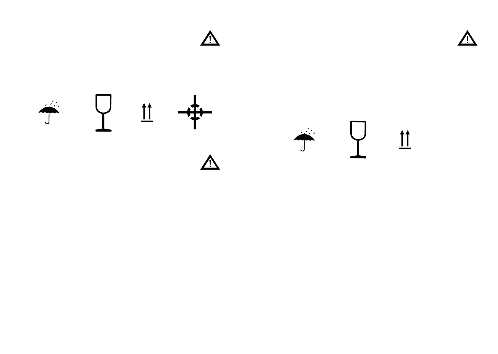
• For correct handling and storage comply with the following symbols:
Protect against moisture Careful: glass Up Centre of gravity
• Do not compress the side walls of the unit or any attached parts by
pulling obliquely on ropes or chains.
• Only remove handling safeguards once all installation work has been
completed.
• When handling in a loading area make sure the unit cannot topple over
or slip.
• Damage caused during transportation must always be reported to the
manufacturer.
8.3 Storage
• If possible the unit should be stored in a closed room until nal
installation.
• If the unit is stored in the open it must be covered over with tarpaulins
and open underneath, to allow condensation to drain o.
• If the unit has been packed for transportation by sea the packaging must
not be damaged or opened during transit and storage.
• For correct storage comply with all storage and handling symbols:
Protect against moisture Careful: glass Up
Table of contents
Other Eclipse Magnetics Water Filtration System manuals


Popular Water Filtration System manuals by other brands

Spectra Watermakers
Spectra Watermakers NEWPORT 400 Mk II Installation & owner's manual

Everpure
Everpure SC10-11 Specification sheet

Hayward
Hayward HCF Series Installation and operation manual

Premier
Premier WH-LD Installation, operation and maintenance manual

multivac
multivac 310-MS manual

SK magic
SK magic WPU-IAC302 manual

Clack
Clack CF1044-3B Installation, operation & maintenance manual

GE
GE Profile PNRQ21LBN Owner's manual and installation

VWR
VWR Puranity PU 15 System instruction manual

Filtreco
Filtreco Basic combi drum 25 user manual

KENT
KENT Supreme Instruction handbook

Pentair
Pentair FC Series Installation, operation, maintenance guide


