ECO Charge BMM User manual
Battery Monitoring
Module (BMM)
Operator / Installer Manual

2
WARNINGS
Keep open flames
away from batteries
on charge.
Risk of battery
explosion.
Be aware of
battery fumes
and electrolyte.
Do not dispose
of batteries in
the garbage.
Electrical hazard
exists inside the
charger, do not
remove the
side cover.
Always recycle lead
acid batteries.
Battery electrolyte
is highly corrosive.
Wear eye protection
when working near
batteries.

3
Contents
Warnings ....................................................................................................................................... 2
Contents ........................................................................................................................................ 3
Overview ....................................................................................................................................... 4
Installation .................................................................................................................................... 5
Configuration .............................................................................................................................. 8
Operation ....................................................................................................................................11
LED Function Indicator ........................................................................................................11
Voltage Imbalance Monitoring ......................................................................................... 12
Water Level Monitoring ........................................................................................................13
Troubleshooting ......................................................................................................................14
Maintenance ..............................................................................................................................15
Service & Warranty ................................................................................................................16
Specifications ............................................................................................................................17
BMM Serial Number
BMM Part Number
Date Supplied
Battery Model
Purchaser
Purchase Invoice Number
Fleet Number

4
Overview
13
4
5
7
6
1
2
3
4
DC Supply Terminals
Tri-color LED
Temperature Sensor
Communications Toroid
6
5
7
Electrolyte Sensor
Midpoint Voltage Sensor
Module Housing
Battery Monitoring
Module (BMM)
2
This guide covers the installation of a BMM and configuration of a BMM
and associated XHF Series Charger. For instructions on the advanced
functionality of the BMM data logging and analysis features available in the
Charger Interface Software Manual, contact your EcoCharge dealer.

5
Installation
NOTE: Before attempting installation, please read through the complete
installation instructions. The battery to be fitted should be disconnected from
any load prior to installation.
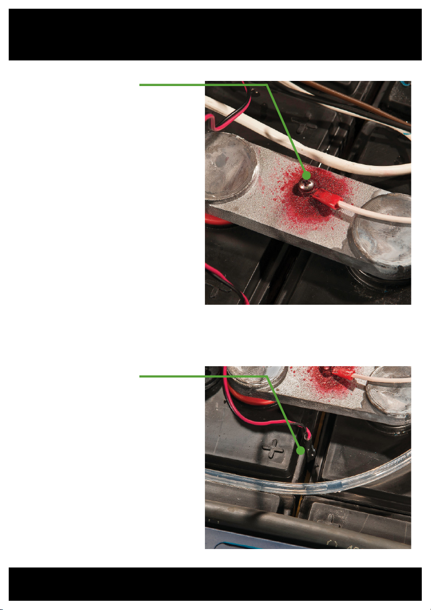
Communications and
Current Sensing Toroid
The Communications Toroid
requires the negative lead to
be removed from the battery
and placed through the toroid
and re-secured to the negative
battery terminal. Alignment of
the toroid should be made so
that the cable exits the toroid
away from the battery terminal.
Keep at least 8in (20cm)
clearance between the toroid
and the positive battery lead. A
half-sleeve on the toroid housing
is provided to secure the toroid
to the battery cable by cable tie.
Unit Location
The BMM module is designed
to sit directly on top of the
battery surface. For optimum
Bluetooth®range, locate the
module near any openings in
the battery enclosure. Cable ties
are supplied to secure the unit
to the battery straps as shown.
6
DC Supply & Voltage
Midpoint Sensor
The DC Supply wires are
terminated with ring terminals
for easy fastening to the
battery with the supplied
screws. The positive (RED) and
negative (BLACK) wires should
be fastened to the top of their
respective battery terminal
posts. The Midpoint Voltage
(WHITE) wire should be
fastened to strapping or a
terminal as close as possible
to the voltage midpoint of
the battery. It is recommended
to coat wire terminations
with corrosion inhibitor before
installation.
Temperature Sensor
The ideal location for the BMM
temperature sensor is between
the cells at the center of the
battery. Depending on the
battery type and construction,
this may not be practical. The
alternative location is cable tied
to the underside of a segment
of lead strapping. An additional
temperature sensor is built-in to
the BMM module.
Installation - continued

7
1
2
3
Electrolyte Sensor
Installation of the electrolyte sensor requires care and consideration of the cell’s
internal construction. If not required, the electrolyte sensor should be removed from
the BMM by cutting the brown sensor wire at the entry point to the BMM module.
8
Configuration
BMM Configuration
Before use, both the BMM and the charger require configuration to enable
the Automatic Profile Configuration (APC) feature.
The following instructions cover:
1. Connecting to the charger
2. Configuring the BMM with the correct battery rating details.
(see page 9).
3.Configuring the charger to enable APC functionality (see page 10).
This step applies to all chargers intended to be used with the BMM.
Required for configuration:
• The BMM installed on the battery.
• A XHF Series Charger
• Standard-A to Mini-B USB cable.
• PC or laptop running Windows Vista or later with Charger
Interface software v7.4 or later.
• Password for BMM configuration
access.
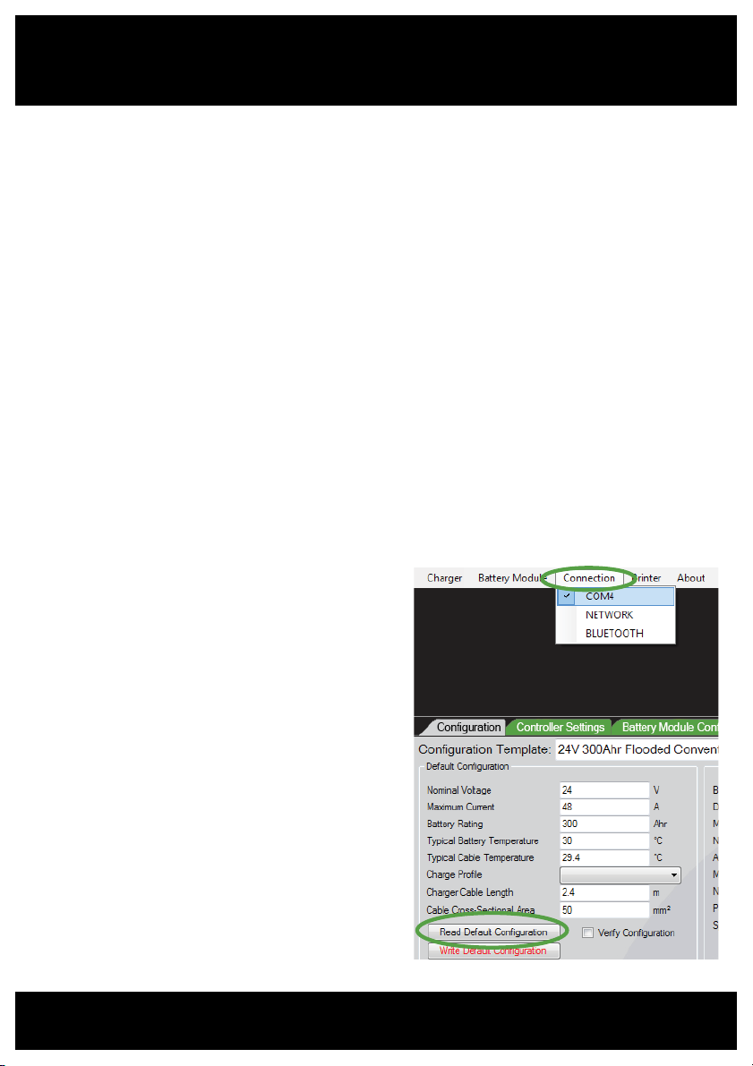
1. Setup Communication via
Charger Interface
• Connect the BMM-equipped
battery to any XHF Series
charger, connect the charger to
the PC via USB and open the
Charger Interface software.
• From the Connection menu,
ensure the appropriate COM port
is selected for the USB interface.
• Verify communications with the
charger by selecting Read Default

9
Configuration.
- If successful, the Voltage and Current details will populate the data
fields.
2. Program BMM with Configuration Parameters
• Enable the Battery Module Configuration tab from the Battery Module
menu.
• From the Battery Module Configuration tab, choose the appropriate
battery type from the template drop-down list. Click Use Values to
populate the parameter fields with the template’s parameters.
• To load the configuration parameters into the BMM module, click Write
Configuration.
• The BMM configuration can be confirmed by clicking Read
Configuration, and checking that the correct values are returned
to the parameter fields.
3. Create a BMM Identifier
The BMM should be given a unique name which allows quick identification
of the battery when reading charge logs.
• Enter a unique name in the Identification field
• Click Write to program the BMM with the new name.
- A useful name may include any combination of the site location,
truck ID, or battery ID numbers.

10
Charger Configuration
Configuration of your XHF Series charger for Automatic Profile
Configuration (APC) can be achieved by configuration via the Charger
Interface Software.
• Connect your PC to the charger via USB and ensure the charger has AC
supply.
• Check that the Charger Interface is communicating with the charger by
following the Setup steps on page 8.
• From the Charger menu, enable the Configuration tab, and ensure the
tab is visible.
• From the Configuration Template drop-down list, choose the option
“APC Enabled”.
• Ensure the adjacent drop-down lists are appropriate for charger type
and AC supply.
• Click the Use Values button to populate the parameter fields below.
•
Click Write Default Configuration to program the charger with the
selected parameters.
• Chargers intended for high rate charging should have the additional
parameter “Use Fast Charge Profile” checked, under the Controller
Settings tab.
To confirm successful configuration, the charger front display will read
“APC Enabled”.
Configuration - continued

11
Green LED: Standby
Flashes once every 2 seconds to indicate ready to-charge standby status.
Red LED: Alarm
Every 2 seconds: Water level low Every 8 seconds: State of charge low
Every 4 seconds: Temperature high,
low or sensor failed Every 10 seconds: State of health low
Every 6 seconds: Voltage imbalance Every 12 seconds: Other error has
occurred
Yellow LED: PLC Comms
Double flash every 2 seconds when communicating with the connected charger
via the battery cable.
Blue LED: Bluetooth®Comms
Flashes when a Bluetooth®device is connected to the BMM.
Operation of the BMM module is automated once installed and configured.
• Connect the BMM-equipped battery to an APC-enabled XHF Series
charger.
- The charger must display “APC Enabled” for BMM auto-configuration
operation.
• Disconnect and reconnect the battery from the charger.
- The charger will read the configuration from the BMM module and the
charge cycle will commence.
Refer to your XHF Series charger documentation for information specific to
your charger’s operation.
LED Function Indicator
The BMM module indicates various states of
operation via a 4 color LED on the top surface
of the module.
Operation / LED Function Indicator
See the Troubleshooting section for descriptions of and resolutions to BMM
alarms.

12
Battery Equalization
The BMM incorporates a Midpoint Voltage Sensor to allow monitoring of cell
imbalance.
• Voltage measured via the Midpoint Voltage Sensor on the battery is
monitored to ensure it remains within 0.5V of half the battery voltage.
• If the voltage moves outside this range a non-urgent Voltage Imbalance
alarm is triggered. The BMM then schedules an equalization charge to
commence following the current charge if connected, or following the
next completed charge.
• Should the midpoint voltage imbalance persist, further equalizations will
be scheduled. Repeated Voltage Imbalance alarms that will not clear
should be investigated as this indicates a potential battery problem.
Enabling Voltage Imbalance Monitoring
To enable voltage imbalance monitoring, ensure the BMM equipped battery
and charger are connected to a PC with Charger Interface software and
select the Voltage Imbalance Monitoring option under the Battery Module
Configuration tab.
Voltage Imbalance Monitoring

13
If installed, the electrolyte sensor allows the BMM to monitor the battery
electrolyte level. Should a low water level be detected, with Water Level
Monitoring enabled the BMM can perform the following operations:
• Display a Low Water alarm on the connected XHF series charger
display (configured for BMM operation)
• Initiate a top-up of the battery following a charge, provided both the
XHF series charger and the battery are fitted with an auto-watering
system.
Enabling Water Level Monitoring
To enable water level monitoring , ensure the BMM equipped battery and
charger are connected to a PC with Charger Interface software and select the
Water Level Monitoring option under the Battery Module Configuration
tab.
Water Level Monitoring

14
Troubleshooting
Problem Possible Cause Remedy
Water Level
Alarm
Electrolyte Sensor
indicating low cell
electrolyte
Check all cells for electrolyte level,
top up as required.
Check installation of electrolyte
sensor probe is as described in
the Installation section of this
document.
If not required, the electrolyte sensor
probe may have been removed from
the BMM module during installation.
Temperature
Alarm
Temperature sensors
indicating temperatures
outside the range
specified in BMM
configuration.
Check installation of remote
temperature sensor is as described
in the Installation section.
Voltage
Imbalance
Alarm
Sensor at the voltage
midpoint on the battery
indicating 0.5V outside
the half-battery-voltage.
The BMM automatically schedules
an equalize charge on this alarm
occurrence. Regular occurrence
indicates poor battery condition or
incorrect installation.
Check installation is as described in
the Installation section.
Charger
Indicates
Config Error
Communications
toroid may be installed
incorrectly.
Ensure installation is as described in
the Installation section.
No Charger
Comms/
No LED Activity
DC supply terminals loose
or corroded.
Ensure terminals are routinely
checked for secure fit and clean,
corrosion free condition. Always
follow battery maintenance
guidelines.
No Bluetooth®
Connectivity
BMM is too far from
device or enclosed a
conductive housing.
Ensure the BMM is located near
openings in the battery enclosure.
Establish unobstructed line-of-sight
path between BMM and reading
device, and move as close as
possible to the BMM.

15
Once installed on the battery, the BMM module requires no maintenance
other than to ensure the module and its various peripherals are secure and
clear of excess battery acid.
Routine checks on the condition of DC Supply and Midpoint Voltage terminals
should be made and any accumulated corrosion removed according to the
battery maintenance documentation.
Typical BMM Installation
Maintenance
BMM Module Negative DC Supply Communications ToroidMidpoint Voltage Sensor
Electrolyte Sensor Temperature Sensor Positive DC Supply

16
Service & Warranty
Service
Contact your local EcoCharge Dealer for service or repair.
Warranty
Enatel Motive Power warrants the product is free from defects
in material and workmanship and agrees to remedy any defect
(or at its option replace the product) for a period of one year from the
date of purchase. This warranty covers parts only.
This warranty will not apply to any product that is improperly installed,
misused, abused, used in ways the product was not designed, altered
or repaired in any way which may affect the performance or reliability of
operation, sustained damage by power surges or electrical storms, or
sustained shipping damage, or repaired by any unauthorized repair center.
Please contact your local EcoCharge dealer for repair.
Enatel Motive Power makes no other warranties, express or implied,
including any warranty of fitness for a particular purpose. In no event shall
Enatel Motive Power be responsible for indirect or consequential damages
or lost profits even if Enatel Motive Power has been advised of the possibility
of such damages. Enatel Motive Power’s sole obligation shall be the repair
or replacement of a nonconforming product.

17
Specifications
Dimensions (in): 4.33L x 2.12W x 11.0H
Toroid Internal Diameter (in): 0.74
Weight (oz): 11.6
Environmental Specifications
Ambient Temp. Range: -5ºF to 122ºF
(max. output power is derated above 122ºF)
Storage Temp.: -68ºF to 158ºF
Humidity: 5-95% RH (non-condensing)
Bluetooth® Specifications: Class 1 Bluetooth®2.0
Contains FCCID: T9JRN41-3
The Bluetooth®word mark and logos are registered trademarks owned by
Bluetooth®SIG, Inc. and any use of such marks by Enatel Motive Power
is under license.

Notes


Manufactured by:
Contact Your Local Dealer:
Enatel Motive Power Ltd
66 Treffers Road, Christchurch 8042, New Zealand.
Ph +64-3-366 4550 Fax +64-3-366 0884
www.enatel-mp.com
Battery Monitoring Module (BMM) Operator/Installer
Drawing: 150205A
Copyright © 2015 Enatel Motive Power
Table of contents


