Tenma 72-10465 User manual

www.element14.com
www.farnell.com
www.newark.com
www.cpc.co.uk
TM
TM
Page <1> V1.010/01/18
Operating Manual
72-10465 LCR Meter

www.element14.com
www.farnell.com
www.newark.com
www.cpc.co.uk
TM
TM
Page <2> V1.010/01/18
Table of Contents
I. General Characteristics and Safety Notice. . . . . . . . . . . 3
II. Ambient Conditions . . . . . . . . . . . . . . . . . . . . . . . 3
Ill. Function Characteristics . . . . . . . . . . . . . . . . . . . . 3
IV. Impedance Parameters . . . . . . . . . . . . . . . . . . . . . 4
V. Measurement Mode . . . . . . . . . . . . . . . . . . . . . . . 4
VI. LCD Display Instructions (shown in Figure 2) . . . . . . . . . 5
VII. Instructions of key functions of 72-10465 front panel
(Shown in Figure 3) . . . . . . . . . . . . . . . . . . . . . . . 6
VIII. Operation Guideline . . . . . . . . . . . . . . . . . . . . . . . 6
IX. Fast Application Guideline . . . . . . . . . . . . . . . . . . . 9
X. PC Communication Protocol . . . . . . . . . . . . . . . . . . 11
XI. Technical Indicators . . . . . . . . . . . . . . . . . . . . . . . 11
XII. Battery Replacement . . . . . . . . . . . . . . . . . . . . . .14
XIII. Maintenance . . . . . . . . . . . . . . . . . . . . . . . . . . . 14

www.element14.com
www.farnell.com
www.newark.com
www.cpc.co.uk
TM
TM
Page <3> V1.010/01/18
I. General Characteristics and Safety Notice
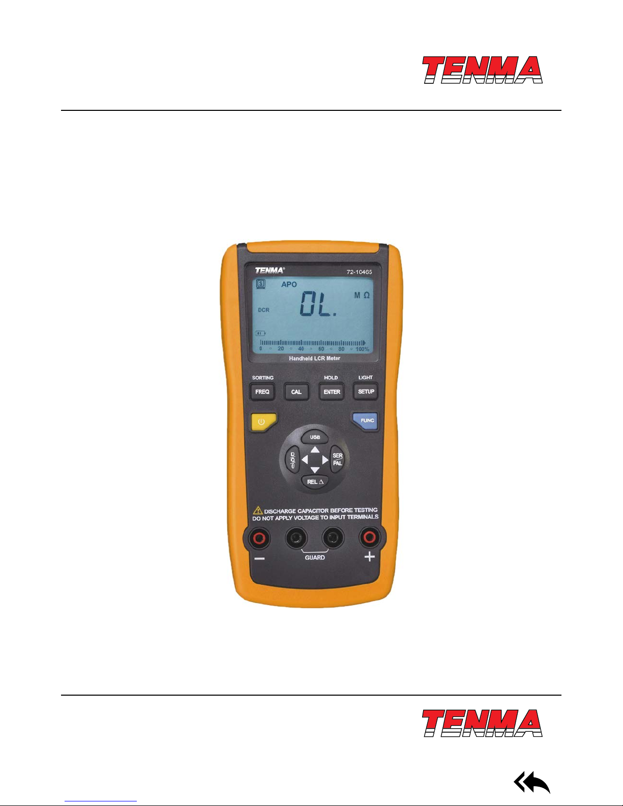
The 72-10465 LCR meter features an easy to read dual display measurement of 19999/1999. It also has serial and parallel
measurement modes which can be used to select quality factor, loss factor, phase location angle, and equivalent resistance
of measure articles. Intelligent detection and ve different test frequencies enable accurate readings for all sizes of capacitors
and inductors. The user can also access the stored data on a PC with the included USB connection and interface software.
The compact size and case make this unit far more portable than a bench top meter.
Measurement Range and Precision
L: 20mH---2000H Best accuracy (0.5% +5);
C: 200pf---20mF Best accuracy (0.5% +5);
R: 20Ω---200MΩ Best accuracy (0.3% +5);
Impedance/frequency DCR 100/120Hz 1kHz 10kHz 100kHz
0.1-1 1% 1% 1% 1% 1%
1-10 0.5% 0.5% 0.5% 0.5% 0.5%
10-100k 0.3% 0.3% 0.3% 0.5% 0.3%
100k-1M 0.5% 0.5% 0.5% 1%
1M-20M 1% 1% 1%
20M-200M 2% 2% 5%
Remark D<0.1
Note: Please multiply by √1+D2if D exceeds 0.1
Formula to convert capacitance to impedance: Zc=1/2πfC
Formula to convert inductance to impedance: ZL=2πfL
Please abide by the following instructions to ensure safe use of the meter:
1) Do not use the meter in an extreme environment, especially dusty environments, near high radiation, or around amma-
ble substances.
2) Do not attempt to alter, repair, or calibrate the unit yourself. Such work should only be done by a trained professional or
as directed by your distributor.
3) Do not attempt to modify the meter, break insulation, or remove working parts.
4) Be certain that all circuits have been shut down and are free of voltage.
5) Do not apply any input voltage to the meter. Be sure to discharge any electried components such as capacitors.
6) This meter can be powered by two different methods. The rst is by a 9V battery, and the second is by the included USB
cable. USB will also allow the unit to sync data while it is being powered to save the life of the battery.
II. Ambient Conditions
1) Altitude: <2000 meters
2) Storage humidity: = 75% RH
3) Operating environment: 0°C ~ 40°C
4) Storage environment: -20°C ~ +50°C
Ill. Function Characteristics
1) Main display of 19,999 and auxiliary display of 1 ,999
2) Measurement frequency: 1 00Hz/120Hz/1kHz/10kHz/100kHz

www.element14.com
www.farnell.com
www.newark.com
www.cpc.co.uk
TM
TM
Page <4> V1.010/01/18
3) Measurement voltage: 0.6Vrms
4) Output impedance: 120Ω
5) Basic precision: 0.5%
6) LCR automatic identication/manual measurement
7) Measurement of DCR DC resistance
8) Calibration compensation of open circuit/short-circuit
9) Automatic shutdown
10) Relative measurement & sieving function
11) Communication between Mini-USB and PC; Data acquisition/analysis/ statement
IV. Impedance Parameters
Impedance measurement instruments can be classied as DC impedance and AC impedance types. A general multimeter
can be used to measure DC impedance, while a bridging instrument (such as this) can be used to measure AC or DC imped-
ance. The 72-10465 is an intelligent double-display portable LCR digital electric bridge, with DC & AC impedance measure-
ment functions. Impedance is one of the most fundamental parameters to analyze electronic elements and circuits. The
resistance of linear diode is dened by Ohm’s Law as part of a DC power scenario. Ratio of voltage and current is a complex
impedance as part of an AC power scenario. One impedance vector includes one real part (resistance R) and one imaginary
part (reactance X). Impedance is expressed by R+jX in a rectangular coordinate, or expressed by the amplitude of real Z and
phase angle of 0 in a polar coordinate system. See gure 1-1 for relationship.
Reaction is inductive if θ exceeds 0. In other words, reaction is capacitive if θ is less than 0.
V. Measurement Mode
Impedance can be used to measure serial or parallel mode. Impedance of Z under parallel link mode can be expressed by
mutual access of Y. It can be dened as follows: Y= G+ JB. G is conductance and B is admittance.
Rs = IZsl cos θ
Xs = IZsI sin θ
Xs/Rs = tan θ
θ = tan-1(Xs/Rs)

www.element14.com
www.farnell.com
www.newark.com
www.cpc.co.uk
TM
TM
Page <5> V1.010/01/18
Impedance under serial link mode
Rs: Serial mode of resistance
Xa: Serial mode of reaction
Cs: Serial mode of capacitance
Ls: Serial mode of inductance
Admittance parallel mode
Rp: Parallel mode of resistance
XP: Reaction under parallel mode
CP: Parallel mode of capacitance
LP: Parallel mode of inductance
VI. LCD Display Instructions (shown in Figure 2)
Main display instructions of LCD:
(1) USB communication
(2) Calibration of open circuit/short-circuit
(3) Automatic shutdown
(4) Relative measurement
(5) Main display
(6) Auxiliary display
(7) Analog bar
(8) Sieving tolerance mode
(9) Data retention
Other denitions:
1 ) LCR: Automatic identication mode
2) Lp: Parallel measurement mode for inductance
3) Ls: Serial measurement mode for inductance
4) Cp: Parallel measurement mode for capacitance
5) Cs: Serial measurement mode for capacitance
6) Rp: Parallel measurement mode for resistance
7) Rs: Serial measurement mode for resistance

www.element14.com
www.farnell.com
www.newark.com
www.cpc.co.uk
TM
TM
Page <6> V1.010/01/18
8) DCR: DC resistance measurement mode
9) D: Loss factor
10) Q: Quality factor
11) θ: Phase location angle
12) ESR: Equivalent serial resistance
13) EPR: Equivalent parallel resistance
14) DUT: Articles to measure
15) Key continuation can be expressed by pressing key for less than 1s or more than 2s.
VII. Instructions of key functions of 72-10465 front panel
(Shown in Figure 3)
(1) LCD display zone
(2) Frequency selection key/sieving function key
(3) Calibration key of open circuit/short -circuit
(4) Bootstrap/shutdown key
(5) USB communication function
(6) Selection function of auxiliary parameter
(7) Relative measurement function
(8) Testing input terminal
(9) Shielding protection terminal
(10) Serial/parallel function
(11) Selection for inductance, capacitance & resistance measurement
(12) Conrmation key/data retention
(13) Sieving setting
VIII. Operation Guideline
1. Automatic measurement
Default status is set to automatic identication mode (AUTO LCR) after powering on.
Default frequency is 1 K. Instrument will identify impedance characteristics of articles to measure automatically under auto-
matic mode. It also will select main parameter, auxiliary parameter of L, C or R and suitable serial/parallel mode automatically.
Correspondence of main parameter and auxiliary parameter under automatic mode is as follows:
Capacitance CLoss Factor D
Inductance LQuality Factor Q
Resistance RPhase location angle θ
Serial/parallel mode can be determined according to impedance of articles to measure under automatic measurement mode.
Parallel mode can be selected under higher impedance (of more than 10kΩ). Serial mode also can be selected under lower
impedance (of less than 10kΩ).
2. Data retention
Please press “HOLD” key for data retention during measurement. In the meanwhile, LCD can display data retention symbol
of “ ”. Please press “HOLD” key again to exit data retention and return to normal measurement mode.
3. Measurement parameter under L/C/R mode
Please select corresponding parameters under manual L/C/R mode.
1) Selection of main parameter: Default status is AUTO LCR during power on.
Please select “FUNC” key to select parameters of “AUTO LCR→AUTO L→ AUTO C→AUTO R→DCR→AUTO LCR”.
2) Selection of auxiliary parameter: Please press “SER/PAL” key under corresponding main parameter measurement mode

www.element14.com
www.farnell.com
www.newark.com
www.cpc.co.uk
TM
TM
Page <7> V1.010/01/18
for switch over of serial/parallel measurement mode. Please press “D/Q/θ” key to select auxiliary parameters of “D”, “Q”
and “ESR” (Note: Please select serial measurement mode of “ESR” or parallel measurement mode of “RP”) Auxiliary
parameter can be neglected quantitatively under “AUTO R” or “AUTO DCR” mode.
Note:
A. Please measure capacitance under “AUTO LCR” mode. Please substitute loss factor of auxiliary parameter of D by
equivalent parallel resistance of Rp if capacitance is less than 5pF.
B. Some parameters of auxiliary parameter will not be displayed on LCD when entering into “AUTO R” or “AUTO DCR” for
measurement under “AUTO LCR” mode.
4. Measurement frequency
“1kHz→10kHz→100kHz→100Hz→120Hz→1kHz”.
72-10465 can provide 5 frequency testing points, namely, 100Hz/120Hz/1kHz/10kHz/100kHz. Bootstrap default frequency
is 1K and user can press “FREQ” key to select different frequency points for measurement of “1KHz→10kHz→
100kHz→100Hz→120Hz→1kHz”.
Note: DC impedance is measured under “AUTO DCR” mode and measurement frequency also can be neglected.
5. Measurement of deviation proportion
Deviation measurement is used to compare with deviation ratio of 2 elements.
Main display is main value of measured elements. Auxiliary display is deviation percentage. Main LCD display can be typed
in automatically as nominal value.
Percentage display scope: -99.9%~99.9%
Display percentage: REL% = ( D
cur
D
ref
) / D
ref
* 100%
DCUR : Main parameter of measured elements
DREF : Typed nominal value
Auxiliary display is “OL%” and main display is main parameter of measured elements if D
cur
> 2D
ref
or 2D
cur
< D
ref
1) Entry into deviation measurement
User can press “FUNC” key to select suitable modes of “AUTO L”, “AUTO C”, “AUTO R” or “AUTO DCR”. Please conrm
that testing terminal has been connected to measured element and press “REL” key to enter into deviation proportion meas-
urement mode. LCD will display “ ” symbol. Main display is main parameter of measured elements and auxiliary display is
display percentage deviation by way of percentage. User also can press “REL” key for main display of nominal value. “ ”
symbol on LCD will icker and display. Percentage deviation also can display for auxiliary display by way of percentage. User
also can press “REL” key to return to normal deviation measurement mode again.
2) Exit of deviation measurement
User can press “REL” key for a long time to exit deviation measurement and return to normal mode.
6. Sorting Measurement
Sorting measurement mode is used to sieve elements of which main parameter is within a certain scope quickly. User can
press “FUNC” key to select suitable modes of “AUTO L”, “AUTO C”, “AUTO R” or “AUTO DCR”. Please conrm that testing
terminal has been connected to measured element and press ‘’FREQ” for a long time to enter into sieving mode. LCD will
display “Sorting” symbol. Main display is “PASS” and auxiliary display is main value of measured elements with typed nominal
value and buzzer rings. Main display is “FALL” and auxiliary display is main value of measured elements if exceeding extreme
scope.
1) Setting sorting range
The sorting function range can be set to ±0.25%, ±0.5%, ±1%, ±2%, ±5%, ±10%, ±20% and +80% ~ -20%. Default scope
is ±1%. User can press “SETUP” key for setup under sieving measurement mode. “Range” symbol on LCD ickers and
displays. User can press “ENTER’’ to conrm entry into setting page of main parameter. Final character of main parameter
on LCD ickers. User can press value of “ ” key to decrease value one by one. He also can press “ ” to increase value
one by one. He can press main parameter of “ ” key for rightward movement of cursor position. He can press “ ” key for
leftward movement of cursor position of main parameter with corresponding value adjustment. He can press “ENTUP” key
to enter into sieving scope for setting and ickering of “TOL” ±1 %” symbol on LCD. He can press “ ” or “ ” key to adjust
value within sieving scope. He also can press “ENTER” to conrm setting of sieving & measurement of elements.
2) Exit of sieving mode
User can press “Sorting” key to exit sieving & measurement mode and return to normal mode.

www.element14.com
www.farnell.com
www.newark.com
www.cpc.co.uk
TM
TM
Page <8> V1.010/01/18
7. Calibration function
Calibration function can be used to reduce interference of distribution parameters brought in by testing wires effectively.
Calibration function includes short-circuit calibration and open circuit calibration. Short-circuit calibration can be adopted
to reduce inuence of contact resistance and testing wire resistance to measure low-impedance elements. Open circuit
calibration also can be adopted to reduce inuence of distributed capacitance and distributed resistance of testing wires to
measure high-impedance elements.
1) Entry into calibration function (with inserting images)
User can press “CAL” key for a long time to enter into open circuit for calibration. (As shown in Figure 4,) auxiliary display
on LCD can show “ ” . User also can press ‘’CAL” to begin calibration. (As shown in Figure 5), LCD also will show “ ”
after countdown from 30s to 0.
It refers to nishing calibration of open circuit. User can press “CAL” key to show “ ” (shown in Figure 6) on auxiliary display
of LCD. User can insert short-circuit pieces into testing terminal and then press “CAL” key to begin calibration. (As shown in
Figure 7), LCD will show “ ” after countdown from 30s to 0 to show nishing short-circuit calibration. User also can press
“CAL” key to return to normal measurement mode.
Note: (As shown in Figure 8,) LCD will show “ ” for open circuit calibration.
It refers to calibration failure. Please check if testing terminal is under open circuit status or not to guarantee re-calibration of
open circuit. (As shown in Figure 9), LCD will show “ ” for short-circuit calibration.

www.element14.com
www.farnell.com
www.newark.com
www.cpc.co.uk
TM
TM
Page <9> V1.010/01/18
It refers to calibration failure. Check if testing terminals have been inserted into short-circuit pieces or not to guarantee normal
short-circuit re-calibration.
8. PC communication
Press “PC” key to enter into communication function for “ ” display on LCD. Insert USB wire and start software of PC end
upper host for data transmission. Press “PC” key to exit communication function and interrupt data transmission.
9. Press and hold the “LIGHT” key to activate the LCD backlight. The backlight will automatically shut off after 60 seconds.
10. Auto power off
Power off after about 5 minutes of idling
IX. Fast Application Guideline
1. Selection of serial/parallel mode
Suitable equivalent mode can be selected to gain more precise measurement data. In general, it is suggested to select
serial equivalent mode for low-impedance element (such as less than 100Ω). It is suggested to select parallel equivalent
mode for high-impedance element (such as more than 10kΩ). Serial/parallel equivalent mode also has little inuence for
measurement result.
2. Inductance measurement
1) Press “ ” for power on.
2) Press “FUNC” to display “Lp” on LCD and select inductance measurement gear.
3) Insert inductance into testing port or connect corresponding ttings to measured inductance (shown in Figure 10).
4) To press “FREQ” key to select suitable testing frequency.
5) Press “D/Q/θ” to select auxiliary parameter to measure.

www.element14.com
www.farnell.com
www.newark.com
www.cpc.co.uk
TM
TM
Page <10> V1.010/01/18
3. Capacitors must be discharged completely before measurement.
1 ) Press “ ” for power on.
2) Press “FUNC” to display “Cp” on LCD and select capacitance measurement gear.
3) Insert capacitance into testing port or connect corresponding ttings to measured capacitance (shown in Figure 11).
4) To press “FREQ” key to select suitable testing frequency.
5) Press “110/Q/θ” to select auxiliary parameter to measure.
4. Resistance measurement
1) Press “ ” for power on.
2) Press “FUNC” to display “Rp” on LCD and select capacitance measurement gear.
3) Insert resistance into testing port or connect corresponding ttings to measured capacitance (shown in Figure 12).
4) To press “FREQ” key to select suitable testing frequency.
Note: Auxiliary parameter of resistance measurement will be neglected and auxiliary parameter will not be displayed on LCD.

www.element14.com
www.farnell.com
www.newark.com
www.cpc.co.uk
TM
TM
Page <11> V1.010/01/18
5. Measurement of DC impedance
1) Press “ ” for power on.
2) Press “FUNC” to display “DCR” on LCD and select measurement gear of DC resistance.
3) Insert resistance into testing port or connect corresponding ttings to measured resistance (shown in Figure 13).
Note: Auxiliary parameter and measurement frequency of DC resistance will be neglected and auxiliary parameter will not be
displayed on LCD.
X. PC Communication Protocol
Start PC communication function to connect instrument and computer by USB wire for data acquisition.
Communication parameters:
1) Bit rate : 9600
2) Data bit : 8
3) Start bit : 1
4) Stop bit : 1
5) Inspection : Without
Connection mode is shown in the gure:
XI. Technical Indicators
Note:
1) Testing ambient temperature: 23°C ±5°C; Humidity: =75% R.H
2) Pre-heat for 10 minutes before test;
3) Test on port slot of instruments;
4) Calibrate open circuit/short-circuit before test;
5) The actual measurement and displaying scope of the device go beyond the specied scope in the table; but no accuracy is
specied for the measuring value which goes beyond the scope in the table

www.element14.com
www.farnell.com
www.newark.com
www.cpc.co.uk
TM
TM
Page <12> V1.010/01/18
Function Measurement
mode Frequency Range The Min.
Resolution
Precision ±(a% of reading + b of word
quantity) (under 18°C to 28°C)
L
Inductance
gear
Rs/Rp
100Hz/120Hz
20mH 1μH 1%+5
200mH 0.01mH 0.5%+5
2000mH 0.1mH 0.5%+5
20H 1mH 0.5%+5
200H 0.01H 1%+5
2000H 0.1H 1%+5
20kH 0.001kH 2%+5
1kHz
2000μH 0.1μH 1%+5
20mH 1μH 0.5%+5
200mH 0.01mH 0.5%+5
2000mH 0.1mH 1%+5
20H 1mH 1%+5
200H 0.01H 2%+5
2000H 0.1H 5%+5
10kHz
200μH 0.01μH 1%+5
2000μH 0.1μH 0.5%+5
20mH 1μH 0.5%+5
200mH 0.01mH 1.5%+5
2000mH 0.1mH 2%+5
20H 1mH 5%+5
100kHz
20μH 0.001μH 1%+5
200μH 0.01μH 2%+5
2000μH 0.01μH 2%+5
20mH 1μH 2%+5
200mH 0.01mH 5%+5
CAP
Capacitance
gear
Cs/Cp
100Hz/120Hz
20nF 1pF 2%+5
200nF 0.01nF 0.5%+5
2000nF 0.1nF 0.5%+5
20μF 1nF 0.5%+5
200μF 0.01uF 1%+5
2000μF 0.1uF 2%+5
20mF 0.01mF 2%+5
1kHz
2000pF 0.01pF 1%+5
20nF 0.1pF 1%+5
200nF 0.01nF 0.5%+5
2000nF 0.1nF 0.5%+5

www.element14.com
www.farnell.com
www.newark.com
www.cpc.co.uk
TM
TM
Page <13> V1.010/01/18
Function Measurement
mode Frequency Range The Min.
Resolution
Precision ±(a% of reading + b of word
quantity) (under 18°C to 28°C)
CAP
Capacitance
gear
Cs/Cp
1kHz
20μF 1nF 0.5%+5
200μF 0.01uF 1%+5
2000μF 1uF 1%+5
10kHz
200pF 0.01pF 2%+5
2000pF 0.1pF 1%+5
20nF 1pF 1%+5
200nF 0.01nF 1.5%+5
2000nF 0.1nF 2%+5
100kHz
200pF 0.01pF 2%+5
2000pF 0.1pF 2%+5
20nF 1pF 2%+5
200nF 0.01nF 5%+5
R
Resistance
gear
Rs/Rp
100Hz/120H
200Ω 0.01Ω 1%+5
2kΩ 0.1Ω 0.3%+5
20kΩ 1Ω 0.3%+5
200kΩ 0.01kΩ 0.5%+5
2MΩ 0.1kΩ 1%+5
20MΩ 1kΩ 2%+5
200MΩ 0.1MΩ 2%+5
1kHz
20Ω 1mΩ 1%+5
200Ω 0.01Ω 1%+5
2kΩ 0.1Ω 0.3%+5
20kΩ 1Ω 0.3%+5
200kΩ 0.01kΩ 0.5%+5
2MΩ 0.1kΩ 1%+5
20MΩ 1kΩ 2%+5
200MΩ 0.1MΩ 5%+5
10kHz
20Ω 1mΩ 1%+5
200Ω 0.01Ω 1%+5
2kΩ 0.1Ω 0.3%+5
20kΩ 1Ω 0.5%+5
200kΩ 0.01kΩ 1%+5
100kHz
20Ω 1mΩ 2%+5
200Ω 0.01Ω 2%+5
2kΩ 0.1Ω 1%+5
20kΩ 1Ω 2%+5

www.element14.com
www.farnell.com
www.newark.com
www.cpc.co.uk
TM
TM
Page <14> V1.010/01/18
Important Notice : This data sheet and its contents (the “Information”) belong to the members of the Premier Farnell group of companies (the “Group”) or are licensed to it. No licence is granted
for the use of it other than for information purposes in connection with the products to which it relates. No licence of any intellectual property rights is granted. The Information is subject to change
without notice and replaces all data sheets previously supplied. The Information supplied is believed to be accurate but the Group assumes no responsibility for its accuracy or completeness, any
error in or omission from it or for any use made of it. Users of this data sheet should check for themselves the Information and the suitability of the products for their purpose and not make any
assumptions based on information included or omitted. Liability for loss or damage resulting from any reliance on the Information or use of it (including liability resulting from negligence or where the
Group was aware of the possibility of such loss or damage arising) is excluded. This will not operate to limit or restrict the Group’s liability for death or personal injury resulting from its negligence.
Tenma is the registered trademark of the Group. © Premier Farnell Limited 2016.
Function Measurement
mode Frequency Range The Min.
Resolution
Precision ±(a% of reading + b of word
quantity) (under 18°C to 28°C)
R
Resistance
gear
DCR
200Ω 0.01Ω 1%+5
2kΩ 0.1Ω 0.3%+5
20kΩ 1Ω 0.3%+5
200kΩ 0.01kΩ 0.5%+5
2MΩ 0.1kΩ 11+5
20MΩ 1kΩ 21+5
200MΩ 0.1MΩ 21+5
Note: The precision is evaluated if D is less than 0.1. Ae = Ae * √1+D2if D exceeds
0 1 (Ae· Precision)
XII. Battery Replacement
Warning
Please replace the battery immediately when
the “ - “ prompt is displayed to avoid errors in
measurement.
Please replace the old battery with a new
alkaline 9V battery.
XIII. Maintenance
1) Cleaning
Please power off and remove battery and external power before cleaning. Please use a damp, soft cloth to wipe away any
direct and debris; do not allow water to drip inside of the case. The meter can not be used until the case is clean and dry.
2) Moisture prevention
Please use instruments in dry environment and store them in dry locations after use. Please power off the unit immediately
and remove battery if water begins to penetrate the casing. Do not detach the casing from the meter. Please contact your
dealer or distributor for repair.
3) Repair
Please inspect the battery or external power rst if there is power on failure. Please check if “ ” key is invalid or not.
Please check if testing wires are excellent with excellent contact between clip in testing port and element foot or not for ab-
normal measurement result. Please conrm correct operation and use. It is not allowed to detach shell or replace element &
circuit individually. Please contact related dealers or after-sales service agents of our company for repair conrmation failure.
Other manuals for 72-10465
3
Table of contents
Other Tenma Measuring Instrument manuals

Tenma
Tenma 72-3500 User manual

Tenma
Tenma ST-8920 User manual

Tenma
Tenma 72-3515 User manual

Tenma
Tenma ST-91 User manual

Tenma
Tenma Smart Tweezer ST-5S-BT2 User manual

Tenma
Tenma 72-7935 User manual

Tenma
Tenma 72-7222 User manual

Tenma
Tenma 72-8170 User manual

Tenma
Tenma 72-10465 User manual

Tenma
Tenma 72-7712 User manual

Tenma
Tenma 72-2985 User manual

Tenma
Tenma 72-10465 User manual

Tenma
Tenma TEN01056 User manual

Tenma
Tenma 72-7228 User manual

Tenma
Tenma 72-1025 User manual

Tenma
Tenma 72-7800 User manual

Tenma
Tenma ST-95 User manual

Tenma
Tenma 72-942 User manual

Tenma
Tenma 72-8150 User manual

Tenma
Tenma 72-14415 User manual