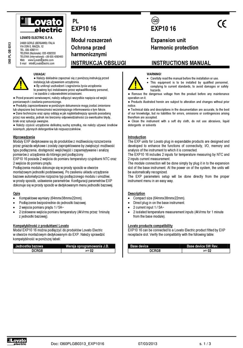
manuals.online logo
Brands
  1. Home
  2. •
  3. Brands
  4. •
  5. LOVATO ELECTRIC
  6. •
  7. Measuring Instrument
  8. •
  9. LOVATO ELECTRIC DME D300T2 User manual

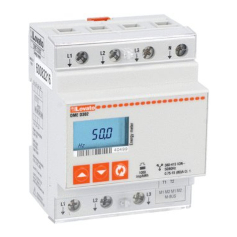
LOVATO ELECTRIC DME D300T2 User manual

Doc: I306PLGB0411 20/04/2011 s. 1 / 7
PL
DME D300T2 DME D300T2
Liczniki energii, trójfazowe, Three-phase direct connection
podłączenie bezpośrednie energy meter
INSTRUKCJA OBSŁUGI INSTRUCTIONS MANUAL
●Przed pracami serwisowymi należy odłączyćwszystkie napięcia od wejść
pomiarowych i zasilania pomocniczego.
●Produkty zaprezentowane w poniższym dokumencie mogązostaćzmienione
lub ulepszone bez konieczności wcześniejszego informowania o tym.
●Dane techniczne oraz opisy oddająw jak najdokładniejszy sposób posiadanąprzez
nas wiedzę, jednak nie bierzemy odpowiedzialności za ewentualne błędy, braki oraz
sytuacje awaryjne.
●W układzie należy zamontowaćrozłącznik (wyłącznik), który musi znajdować
sięniedaleko urządzenia i byćłatwo dostępny dla operatora. Musi spełniaćwymogi
następujących norm: IEC/ EN 61010-1 § 6.12.2.1.
●Należy montowaćurządzenia w obudowie o minimalnym stopniu ochrony IP51.
●Należy czyścićurządzenie delikatnąsuchąszmatką, nie należy używaćśrodków
ściernych, płynnych detergentów lub rozpuszczalników.
●Remove eventual dangerous voltage from the product before any maintenance
operation on it.
●Products illustrated herein are subject to alteration and changes without prior notice.
●Technical data and descriptions in the documentation are accurate, to the best of our
knowledge, but no liabilities for errors, omissions or contingencies arising therefrom are
accepted.
●A circuit breaker must be included in the electrical installation of the building. It must
be installed close by the equipment and within easy reach of the operator.
It must be marked as the disconnecting device of the equipment:
IEC /EN 61010-1 § 6.12.2.1
●Fit the instrument in an enclosure or cabinet with minimum IP51 degree protection.
●Clean the instrument with a soft dry cloth, do not use abrasives, liquid detergents or
solvents.
Spis treści Strona
Wprowadzenie 1
Opis 2
Wybór pomiarów 2
Dioda metrologiczna LED 3
Wskaźnik przepływu energii 3
Programowalne wyjście statyczne 3
Programowalne wejscie AC 3
Dostęp do I/O 3
Funkcje zaawansowane 3
Ustawianie parametrów (setup) 4
Tabela parametrów 4
Wymiary mechaniczne (mm) 6
Schematy podłączeń6
Dane techniczne 7
Index
Page
Introduction
1
Description
2
Selection of readings
2
Metrological LED
3
Energy flow indication
3
Programmable static outputs
3
Programnmable AC input
3
A
ccess to I/Os
3
A
dvanced functions
3
Parameter setting (setup)
4
Setup parameter table
4
Mechanical
dimensions (mm)
6
Wiring diagrams
6
Technical characteristics
7
Wprowadzenie
DME D300T2 jest trójfazowym licznikiem energii czynnej i biernej,
do bezpośredniego podłączenia w układach o prądzie do 63A.
Dokładność pomiaru energii jest zgodna z wymogami normy EN50470-3 (klasa
B MID).
Poza pomiarami energii, umożliwia pomiar 45 parametrów elektrycznych, które
można wizualizowaćna podświetlanym wyświetlaczu LCD.
DME D300T2 posiada obudowęmodułowąo szerokości 4 modułów (4U,
72 mm) i dostarczany jest z osłonąochronnązacisków w komplecie.
Introduction
The DME D300T2 is a three-phase active and reactive energy meter for direct
connection, for currents up to 63A.
The energy accuracy is compliant with reference standard EN50470-3 (MID
class B).
Apart from energy metering, it can measure additional indications, for a total of
45 measurements that can be visualized on the back lighted LCD display.
The DME D300T2 has a standard 4U (72mm wide) modular housing and is
supplied with sealable terminal blocks.
I306PLGB0411
UWAGA!
●Należy dokładnie zapoznaćsięz poniższa instrukcjąprzed
instalacjąlub używaniem urządzenia.
●By uniknąć uszkodzeńi zagrożenia życia urządzenia
te powinny byćinstalowane przez wykwalifikowany personel,
i w z
g
odzie z od
p
owienimi
p
rze
p
isami.
WARNING!
Carefully read the manual before the installation or use.
This equipment is to be installed by qualified personnel,
complying to current standards, to avoid damages or safety
hazards.
Doc: I306PLGB0411 20/04/2011 s. 2 / 7
Opis
Obudowa modułowa 4U (72mm) do montażu na szynie DIN.
Podłączenie bezpośrednie, maksymalnie do 63A.
Pomiar energii czynnej zgodnie z normąEN50470-3 (klasa B).
Podświetlany wyświetlacz LCD.
Licznik: 6 cyfr +1.
3 przyciski do wyboru pomiarów i programowania.
Liczniki całkowite energii czynnej i biernej.
Liczniki częściowe energii czynnej i biernej, z możliwościąkasowania.
Licznik godzin, całkowity i częściowy.
Dioda LED sygnalizacyjna zużycie energii czynnej.
Wskaźnik zużycia chwilowego (moc czynna).
2 programowalne wyjścia statyczne, impulsowe lub alarmowe.
Wejście AC do wyboru taryfy.
Description
Modular DIN-rail housing, 4U (72mm wide).
Direct connection for currents up to 63A.
Active energy measure complies EN50470-3 class B.
LCD display with backlight.
Counter with 6+1 digits.
3 buttons for measure selection and programming.
Total active and reactive energy meters.
Partial active and reactive energy meters, resettable.
Hour counter, total and partial.
Pulse LED for active energy consumption.
Indication of instantaneous consumption (active power).
2 programmable static outputs, for pulse or alarm thresholds.
AC input for two-tariffs selection.
Wybór pomiaru
Wciskając przyciski mamy możliwość wyboru pomiaru
pokazywanego na wyświetlaczu, według porządku z poniższej tabeli.
Każdy pomiar opisany jest odpowiedniąikonąw dolnej części
wyświetlacza.
Przycisk służy do wyboru wyświetlanych pomiarów (całkowite
lub poszczególnych faz).
Normalnie na wyświetlaczu pokazane sąpomiary całkowite (systemu),
opisane symbolem sumy (Σ) w poniższej tabeli. W ich przypadku
na wyświetlaczu widzimy tylko pomiar i jednostkępomiaru.
Kiedy wybrany parametr tyczy sięposzczególnej fazy, w górnej części
wyświetlacza pokazane jest oznaczenie odpowiedniej fazy (L1, L2, L3).
Po upływie jednej minuty, od ostatniej aktywacji jakiegokolwiek przycisku,
urządzenia wraca do wyświetlania strony z pomiarem całkowitej energii
czynnej.
Ikona Str.
Wybór
Format Podstrona
Wybór
kWh Całkowita
energia czynna
000000,0 ΣL1 L2 L3
kWh +
Part
Częściowa
energia czynna
000000,0 ΣL1 L2 L3
kWh
TAR 
Energia czynna
(taryfy)
000000,0 T1 T 2
kvarh Całkowita
energia bierna
000000,0 ΣL1 L2 L3
kvarh +
Part
Częściowa
energia bierna
000000,0 ΣL1 L2 L3
V
Napięcie (fazowe
i międzyfazowe)
000,0
L1 L2
L3
L1L2 L2L3 L3L1
A Prąd 00,00
L1 L2 L3
k
W
Moc czynna 00,00
ΣL1 L2 L3
kva
r
Moc bierna 00,00
ΣL1 L2 L3
kVA Moc pozorna
00,00 ΣL1 L2 L3
PF Współczynnik
mocy
0,00 ΣL1 L2 L3
Hz Częstotliwość 00,0
h
Licznik godzin
(hhhhh.mm)
00000,00
h +
Part
Licznik częściowy
godzin
(hhhhh.mm)
00000,00
kW
+d
Średnia moc
czynna
(zapotrzebowanie
15 min)
00,00
kW+
d +
▲
Maksymalna
średnia moc
czynna (max
zapotrzebowanie)
00,00
Selection of readings
Pressing the buttons it is possible to select the readings on the
display, following the sequence in the table reported below.
Each measure is indicated by the correspondent icon in the lower part of
the display.
The button is used to select the viewing of total readings or specific
phase readings.
Normally the display indicates the total (system) readings, indicated by Σ
symbol in the following table. In this case the display shows only the
measurement and the unit of measure.
When instead the selected measurement is referred to a particular phase,
the icon of that phase (L1, L2 L3) is shown in the upper part of the display.
After one minute has elapsed after the last keystroke, the display moves
automatically back to the total active energy screen.
Icon
Measure page
sel. with
Format Sub-page
select with
kWh
Total active
Energy
000000,0 ΣL1 L2 L3
kWh +
Part
Partial active
energy
000000,0 ΣL1 L2 L3
kWh
TAR 
A
ctive energy
(Tariffs)
000000,0 T1 T 2
kvarh
Total reactive
energy
000000,0 ΣL1 L2 L3
kvarh +
Part
Partial
reactive energy
000000,0 ΣL1 L2 L3
V
Voltage (phase-
neutral ad
phase-phase)
000,0
L1
L2
L3
L1L2 L2L3 L3L1
A
Current
00,00 L1 L2 L3
k
W
A
ctive power
00,00 ΣL1 L2 L3
kva
r
Reactive power
00,00 ΣL1 L2 L3
kVA
A
pparent power
00,00 ΣL1 L2 L3
PF
Power factor
0,00 ΣL1 L2 L3
Hz
Frequency
00,0
h

Hor counter
(hhhhh.mm)
00000,00
h +
Part

Partial hour
counter
(hhhhh.mm)
00000,00
kW
+d

A
verage active
power (15 min
demand)
00,00
kW+
d +
▲

Max avg. active
power (max
demand)
00,00
Te pomiary sąwyświetlane tylko przy ustawieniu programowalnego wejścia
na funkcjęwyboru taryf. Aktualnie wybrana taryfa przez wejście jest wskazana
poprzez migającącyfręznajdującąsie blisko litery T.

These measurements are shown only setting the programmable input
function to Tariff selection. The tariff presently selected by the external input is
indicated by the flashing digit close to letter T.
Doc: I306PLGB0411 20/04/2011 s. 3 / 7
Te pomiary wyświetlane s
ą
tylko przy włączonym parametrze P5-01.
Te pomiary wyświetlane sątylko przy włączonym parametrze P5-02.

These measurements are shown only enabling parameter P5-01.
These measurements are shown only enabling parameter P5-02.
Metrologiczna dioda LED
Czerwona dioda LED, znajdująca sięna panelu przednim, emituje 1000
impulsów na każdąkWh pobranej energii (to jest 1 impuls na każdąWh).
Częstotliwość pulsowania diody LED wskazuje chwilowy przepływ energii
w każdym momencie.
Czas trwania impulsu, kolor diody LED i jej intensywność sązgodne
z odpowiednimi standardami, które definiująużytkowanie umożliwiające
weryfikacje dokładności licznika energii.
Metrological LED
The red LED on the front emits 1000 pulses for every kWh of consumed
Energy (that is, one pulse every Wh).
The pulsing frequency of the LED gives an immediate indication of the
energy flowing in every moment.
The pulse duration, LED colour and intensity are compliant with the
reference standards that define its utilization in order to verify the accuracy
of the energy meter.
Wskaźnik przepływu energii
Kiedy urządzenie wykrywa przepływ energii do obciążenia, na ekranie,
w górnym prawym rogu wyświetlacza, widoczna jest obracająca sięikona.
Kiedy nie ma poboru energii czynnej lub kiedy obciążenie oddaje wartość
mniejsząniżprąd rozruchu, obracająca sięikona znika.
W przypadku niewłaściwego okablowania jednej lub więcej faz (energia
płynie w odwrotnym kierunku, tj. obciążenie podłączono do górnych
zacisków)na wyświetlaczu pojawi siękod błędu Err 3. W takim przypadku
należy sprawdzićpodłączenie.
Energy flow indication
When the device detects a flow of active energy to the load, it shows a
rotating icon in the top-right part of the display.
When there is no active energy consumption or when the load draws less
than the starting current the rotating icon disappears.
Of one ore more phases have been connected in a wrong way (energy flow
in the backward direction, that is load connected to upper terminals) the
display will show the error code Err 3. In this case, check the line in-line out
connections.
Programowalne wyjścia statyczne
DMED300T2 posiada dwa wyjścia statyczne, programowalne niezależnie.
Każde z wyjść statycznych może byćużywane jako wyjście impulsowe lub
jako wyjście sygnalizacyjne (alarmowe) dla przekroczenia ustalonych
limitów.
Podłączenie może byćwykonane w trybie PNP lub NPN. Zobacz schemat
podłączeńi dane techniczne w celu uzyskania większej ilości informacji
o podłączeniu i zakresach
Aktywacja wyjść statycznych oznaczona jest na wyświetlaczu ikoną
i .
Kiedy wyjście zaprogramowane jest generator impulsów możliwe jest
podłączenie licznika energii do:
Zewnętrznego rejestratora danych (jak np. DME CD)
Zdalnego licznika elektromechanicznego
Do sterownika PLC lub innego typu urządzenia.
Kiedy natomiast wyjście pracuje jako wyj. alarmowe to może byćużyte do:
Zrzutu obciążenia
Sygnalizacji alarmu
Uwaga: Podczas ustawiania parametrów (setup) status wyjścia statycznego
nie jest odświeżany.
Programowalne wejście AC
DMED300T2 posiada programowalne wejście AC.
Domyślnie to wejście jest wyłączone. Należy ustawićparametr P4.01
w celu włączenia wymaganej funkcji.
Wejście może byćwykorzystywane do:
Wyboru pomiędzy dwoma różnymi taryfami (T1 i T2),
każda z niezależnymi licznikami energii.
Kasowania liczników częściowych, liczników godzin,
wartości maksymalnego zapotrzebowania poprzez
aktywacjęwejścia.
Warunkowego włączania licznika godzin.
Dostęp do zacisków I/O
Wyjścia statyczne i wejście AC umiejscowione zostały w prawym dolnym
rogu urządzenia.
By uzyskaćdostęp do zacisków I/O należy zdjąć pokrywęochronnąprzy
użyciu małego płaskiego wkrętaka.
Programmable static outputs
The DMED300T2 has two static outputs independently programmable.
Each of the static outputs can be used either as a pulse output or as a
measure threshold output.
The connection can be done in PNP or NPN mode. See schematic
diagrams and technical characteristics for details on the wiring and on the
rating.
The activation of the static outputs is shown on the display through the
and icons.
When one output is programmed as a pulse generator, it allows connecting
the energy meter to:
An external data concentrator (like DME CD)
A remote electromechanical counter
A PLC or other device
When it works as an alarm threshold, it can be used for:
Disconnection of non-priority loads
Alarm signalling
Note: During parameter setting (setup) the status of the static outputs is not
updated.
AC programmable input
The DMED300T2 has a programmable AC input.
By default, this input is disabled. Set the parameter P4.01 in order to
choose the desired function.
The input can be used for:
Selection between two different tariffs (T1 and T2) with
independent energy meters.
Clearing of partial counters, hour meter, max demand
value through activation of the input.
Conditional enable of the hour meter.
Access to I/O terminals
The static outputs and the AC input are placed in the bottom-right side.
To access to the I/O terminals it is necessary to remove the protective
cover, using a small flat screwdriver.
Funkcje zaawansowane
By uzyskaćdostęp do funkcji zaawansowanych, należy zastosować
poniższąprocedurę:
1. Począwszy od dowolnej strony wizualizacji, należy wcisnąć w tym
samym czasie przyciski i przytrzymaćprzez 5 sekund. Jeśli hasło
dostępu jest wyłączone (domyślne hasło = 0000) ekran przejdzie
bezpośrednio do funkcji zaawansowanych (punkt 4), w innym przypadku
sięinformacja, iżnależy wprowadzićnajpierw hasło dostępu (PASS).
2. Należy zwolnićprzyciski. Wyświetlacz czeka na wprowadzenie hasła
i wskazuje 0000. Pierwsza cyfra miga. Wciskając podczas, gdy
cyfra miga, zmieniamy danącyfrę. Wciskając , zmieniamy wybór na
A
dvanced functions
To access the advanced functions, use the following procedure:
1. Starting from any visualization screen, press at the same time for
5s. If the password protection is disabled (factory default, password =
0000), display jumps directly to advanced functions (point 4), otherwise it
will show PASS to inform that the access code must be entered first.
2. Release the buttons. The display now waits for the password and
indicates 0000. The first digit flashes. Pressing while a digit is
flashing, that digit is incremented. Pressing , the selection moves to
Doc: I306PLGB0411 20/04/2011 s. 4 / 7
kolejnącyfrę. Po wprowadzeniu właściwego hasła, należy wcisnąć
przycisk w celu potwierdzenia.
3. Jeśli wprowadzone hasło jest niewłaściwe, na wyświetlaczu pojawi się
komunikat PASS Er, a licznik powróci do normalnej wizualizacji. Jeśli
natomiast hasło jest prawidłowe, urządzenie przechodzi do kolejnego
punktu ustawień.
4. Na wyświetlaczu pojawia siępierwsza pozycja z poniższej listy. Przy
poruszaćsiępomiędzy możliwymi wyborami należy użyćprzycisków
CLEAR P = kasowanie częściowych liczników energii
CLEAR h = kasowanie częściowego licznika godzin (jeśli włączony)
CLEAR d = kasowanie wartości maksymalnego zapotrzebowania
(jeśli włączone)
SETUP = programowanie parametrów
INFO = wersja i sprawdzenie wewnętrznego oprogramowania
--ESC-- = powrót do normalnej pracy
5. By wybraćfunkcjęnależy wcisnąć przycisk do momentu, gdy wybrana
funkcja jest wyświetlana. W celu użycia funkcji kasowania należy
przytrzymaćprzycisk przez 3 sekundy.
6. Jeśli przycisk nie zostałaktywowany przez 60 sekund, wyświetlacz wraca
automatycznie do normalnej pracy.
Hasło – zgubione lub zapomniane
Jeśli hasło zostało zapomniane lub zgubione, po trzech próbach
wprowadzenia niewłaściwego hasła, na ekranie pojawi się6 cyfrowy kod
blokady. Proszęskontaktowaćsięz Serwisem Klienta Lovato Electric i podać
kod blokady. Zwrotnie wysłane zostanie właściwe hasło. Po wprowadzeniu
otrzymanego hasła użytkownik może dokonywaćzmian ustawień(parametr
P1.01).
the next digit. After having entered the right password code, press to
confirm.
3. If the entered password is wrong, the display shows PASS Erand goes
back to normal visualization. If instead the code is correct, it proceeds to
next point.
4. The display shows the first item of the following list. To move through the
list, click
CLEAR P = clearing of partial energy meters
CLEAR h = clearing of partial hour counter (if enabled)
CLEAR d = clearing of max demand values (if enabled)
SETUP = parameters programming (setup)
INFO = revision and checksum of internal software
--ESC-- = returns to normal operation
5. To select a function, press while the desired function is displayed.
For clearing commands, it is necessary to hold down the button for 3s.
6. If the button is never pressed for 60 consecutive seconds, the display
goes back automatically to normal operation.
Lost or forgotten password
If password is lost or forgotten, after three consecutive faulty attempts to enter
the password, the display shows a 6-digit unlock code. Please contact Lovato
electric customer service reporting this unlock code. The right password will be
provided. The user is then free to change setting it as desired in the usual way
(parameter P1.01).
Ustawianie parametrów (setup)
Kiedy wyświetlacz pokazuje SETUP, należy wcisnąć .
Na wyświetlaczu pojawi siękod pierwszego parametru P1-01.
By wybraćkolejne parametry P2-01, P2-01… należy krótko wcisnąć przyciski
.
Kiedy na wyświetlaczu pokazany jest kod parametru, który chcemy
zmodyfikowaćnależy wcisnąć
oNa wyświetlaczu pojawi sięaktualna wartość parametru. Przy użyciu
przycisków możemy modyfikowaćwartość.
oWciskając dokonujemy potwierdzenia i powrotu do wyboru kodów
parametrów.
Jeśli wciśniemy jednocześnie przyciski przez 1 sekundę,
zapamiętamy ustawienia, a urządzenie powróci do normalnej pracy.
Parameters setting
(setup)
While display is showing SETUP, press
The display shows the first parameter code P1-01.
Short-click to move to next parameters P2-01, P2-02… etc use .
When the display indicates the code of the parameter that needs to be
modified, press .
oThe display shows its present value of the parameter. Pushing
the value can be modified.
oConfirm with to go back to parameter code selection.
Pressing buttons together for 1 s, parameters are saved and system
goes back to normal operation.
Tabela parametrów Setup parameters table
Kod Opis Domyślnie Zakres
Code Description
Default Range
P1-01 Hasło 0000
0000 - 9999 P1-01 Password
0000 0000 - 9999
P2-01 Funkcja wyjścia 1 10 PUL /
kWh
OFF - Wyłączone
1000 PUL / kWh
100 PUL / kWh
10 PUL / kWh
1 PUL / kWh
THR – programowalne progi
P2-01 Output 1 function
10 PUL /
kWh
OFF - Disabled
1000 PUL / kWh
100 PUL / kWh
10 PUL / kWh
1 PUL / kWh
THR – Programmable thresholds
P2-02 Pomiar odnoszący siędo
progu wyjścia 1
01
kW (zobacz tabela 1) P2-02 Reference measure for
output 1 threshold
01
kW (see table 1)
P2-03 Próg 1 - ON 100.00
0.00 – 999.99 P2-03 ON threshold 1
100.00 0.00 – 999.99
P2-04 Opóźnienie dla ON progu 1 5 sek.
0 – 9999 sek. P2-04 ON delay 1
5 s 0 – 9999 sec.
P2-05 Próg 1 - OFF 50.00
0.00 – 999.99 P2-05 OFF threshold 1
50.00 0.00 – 999.99
P2-06 Opóźnienie dla OFF progu 1 5 sek.
0 – 9999 sek. P2-06 OFF delay 1
5 s 0 – 9999 sec.
P3-01 Funkcja wyjścia 2 OFF
OFF - Wyłączone
1000 PUL / kWh
100 PUL / kWh
10 PUL / kWh
1 PUL / kWh
THR – programowalne progi
P3-01 Function of output 2
OFF OFF - Disabled
1000 PUL / kWh
100 PUL / kWh
10 PUL / kWh
1 PUL / kWh
THR – Programmable thresholds
P3-02 Pomiar odnoszący siędo
progu wyjścia 2
01
(zobacz tabela 1) P3-02 Reference measure for
output 2 threshold
01 (see table 1)
P3-03 Próg 2 - ON 100.00
0.00 – 999.99 P3-03 ON threshold 2
100.00 0.00 – 999.99
P3-04 Opóźnienie dla ON progu 2 5 sek.
0 – 9999 sek. P3-04 ON delay 2
5 s 0 – 9999 sec.
P3-05 Próg 2 - OFF 50.00
0.00 – 999.99 P3-05 OFF threshold 2
50.00 0.00 – 999.99
P3-06 Opóźnienie dla OFF progu 2 5 sek.
0 – 9999 sek. P3-06 OFF delay 2
5 s 0 – 9999 sec.
Doc: I306PLGB0411 20/04/2011 s. 5 / 7
P4-01 Funkcja wejścia 1 OFF
OFF - Wyłączone
ON - Włączone
TAR – Wybór taryfy
CLr Part – Kasowanie licznika
częściowego energii
CLr Hr – Kasowanie licznika
godzin
CLr dE – Kasowanie
maksymalnego
zapotrzebowania
P4-01 Function for Input 1
OFF
OFF – Disabled
ON - Enabled
TAR – Tariff selection
CLr Part – Clear partial energy
CLr Hr – Clear hour meter
CLr dE - Clear max demand
P5-01 Włączanie licznika godzin OFF
OFF-ON-THR1-THR2-INP P5-01 Hour counter enable
OFF OFF-ON-THR1-THR2-INP
P5-02 Włączanie pomiarów
zapotrzebowania
OFF
OFF-ON P5-02 Enable demand measures
OFF OFF-ON
Opis parametrów
Parameter description
P1-01
–
Jeśli ustawiony jest na 0000 (domyślnie) to hasło ochrony jest wyłączone.
Każde inne ustawienia definiująhasło dostępu do funkcji zaawansowanych.
P1-01
–
If set to 0000 (default) the password protection is disabled.
Any other setting defines the password to access to the advanced functions.
P2-01
–
Definiuje funkcjęwyjścia statycznego nr 1, lista dostępnych poniżej:
OFF -Wyłączone
1000 PUL …1 PUL – Wyjście statyczne nr 1 pracuje jako generator impulsów
do zliczania energii czynnej. Dodatkowo mamy możliwość wyboru ile impulsów
definiuje jednąkWh.
P2-01
-
Defines the function of the static output 1 from the following
list:
OFF -Disabled
1000 PUL …1 PUL Static output 1 operates as a pulse emitter for active energy
count. These selections define the number of pulses sent for every kWh.
THR - Wyjście statyczne nr 1 pracuje jako wyjście alarmowe, dla poziomów minimum
i maksimum, w zależności od wartości ustawionych w parametrach P2-03 i P2-05.
Jeśli P2-03 >= P2-05, to wyjście będzie aktywowane kiedy pomiar zdefiniowany przez
parametr P2-02 jest wyższy niż> P2-03, i dezaktywowane kiedy jego wartość jest
niższa niż< P2-05 (maksymalny limit z histerezą).
Jeśli natomiast P2-03 < P2-05, to wyjście jest aktywowane kiedy pomiar zdefiniowany
w P2-02 jest niższy niżP2-03, i dezaktywowane kiedy jego wartość jest wyższe niż
P2-05 (minimalny limit z histerezą).
P2-02 – Wybór pomiaru do porównania z danym progiem. Zobacz tabela 1.
P2-03 i P2-04 – Próg i opóźnienie dla aktywacji wyjścia. Uwga: pomiary odświerzane
sąco 1 sekundę, to znaczy, że opóźnienie ma zmienność od 0 do +1 sekundy.
P2-05 i P2-06 – Jak wyżej tylko dla deaktywacji wyjścia.
THR -
The static output 1 becomes an alarm threshold for maximum or minimum limit,
depending on values programmed in P2-03 and P2-05.
If P2-03 >= P2-05, then output activates when the measure defined by P2-02 is
higher than P2-03, end de-activates when its value becomes less than P2-05
(maximum limit with hysteresis).
If P2-03 < P2-05, then output activates when the measure defined by P2-02 is lower
than P2-03, end activates when its value becomes higher than P2-05 (minimum limit
with hysteresis).
P2-02 – Selection of measure to compare with thresholds. See table 1.
P2-03 and P2-04 – Threshold and delay for output activation. Note: The
measurements are updated every 1 second, that means that the variability of this
delay is in the range from 0 to + 1 second.
P2-05 and P2-06 – Threshold and delay for output de-activation.
P3-01 .. P3-06
–
Te same funkcje jak w P2-01 .. P2-06, ale odnosząsiędo wyjścia 2.
P3-01 .. P3-06
–
Same function as
P2-01 .. P2-06, but referred to output 2.
P4-01
–
Wybór funkcji programowalnego wejścia:
OFF – wejście wyłączone.
ON – wejście włączone (do zastosowania z funkcjami ogólnymi jak włączanie licznika
godzin).
Tar = wybór taryfy energii (T1 / T2).
ClrPart = kasowanie cześćiowych liczników energii.
Clr Hr = kasowanie licznika godzin.
Clr de = kasowanie maksymalnego zapotrzebowania.
P4-01
–
Selects the function of the programmable input:
OFF – Input disabled.
ON – Input enabled (to be used for general functions like hour meter enabling).
Tar = Selection of energy tariff (T1 / T2).
ClrPart = Clears partial energy counters.
Clr Hr = Clears hour counter.
Clr de = Clears max demand.
P5-01
–
Definiuje działanie licznika godzin:
OFF – licznik godzin wyłączony, nie jest wyświetlany na ekranie.
ON – licznik godzin pracuje (zwiększa wartość) tak długo jak licznik jest zasilony.
THR1 – licznik godzin pracuje (zwiększa wartość) tak długo jak próg zdefiniowany
w parametrach P2-01… P2-06 jest aktywny.
THR2 – licznik godzin pracuje (zwiększa wartość) tak długo jak próg zdefiniowany
w parametrach P3-01… P3-06 jest aktywny.
INP – licznik godzin pracuej (zwiększa wartość) tak długo jak programowalne wejście
jest aktywne. Parametr P4.01 musi byćustawiony na ON.
P5-02 – Włącza kalkulacje i wizualizacjęzapotrzebowania na energięczynną,
chwilowego i maksymalnego.
P5-01
–
Defines the hour counter operation:
OFF –hour counter disabled. It is not shown on the display.
ON – The hour counter is incremented as long as the energy meter is supplied.
THR1 – The hour counter is incremented as long as the threshold defined with
parameters ( P2-01..P2-06) is active.
THR2 – The hour counter is incremented as long as the threshold defined with
parameters ( P3-01..P3-06) is active.
INP – The hour counter incremented as long as the programmabler input is activated.
The parameter P4.01 must be set to ON.
P5-02 – Enable of calculation and visualization of active energy demand and max
demand.
Tabela 1 – pomiary do ustawienia w P2.02 i P3.02 Table 1 - Measures for setting of P2.02 and P3.02
Ustawienia Pomia
r
Setting
Measure
01 kW – Moz czynna 01
kW – Active power 
02 kW
–
Moc czynna, całkowita 02
kW
–
A
ctive power
(total)
03 kW L1
–
Moc czynna fazy L1 03
kW L1
–
A
ctive power L1
04 kW L2
–
Moc czynna fazy L2 04
kW L2
–
A
ctive power L2
05 kW L3
–
Moc czynna fazy L3 05
kW L3
–
A
ctive power L3
06 kvar – Moc bierna 06
kvar – Reactive power 
07 kvar
–
Moc bierna, całkowita 07
kvar
–
Reactive power (total)
08 kvar L1
–
Moc bierna fazy L1 08
kvar L1
–
Reactive power L1
09 kvar L2
–
Moc bierna fazy L2
09
kvar L2
–
Reactive power L2
10 kvar L3
–
Moc bierna fazy L3
10
kvar L3
–
Reactive power L3
11 KVA – Moc pozorna 
11
kVA - Apparent power 
12 KVA
–
Moc pozorna, całkowita
12
kVA
-
A
pparent power (total)
13 kVA L1
–
Moc pozorna fazy L1
13
kVA L1
–
A
pparent power L1
14 kVA L2
–
Moc pozorna fazy L2
14
kVA L2
–
A
pparent power L2
15 kVA L3
–
Moc pozorna fazy L3
15
kVA L3
–
A
pparent power L3
16 V L-L – Napięcie międzyfazowe 
16
V L-L – Phase-to-phase voltage 
17 V L1-L2
–
Nap. międzyfazowe L1-L2
17
V L1-L2
–
Phase-phase voltage L1-L2
18 V L2-L3
–
Nap. międzyfazowe L2-L3
18
V L2-L3
–
Phase-phase voltage L2-L3
19 V L3-L1
–
Nap. międzyfazowe L3-L1
19
V L3-L1
–
Phase-phase voltage L3-L1
20 V L-n – Napięcie fazowe 
20
V – Phase voltage 
21 V L1
–
Napięcie fazowe L1-N
21
V L1
–
Phase voltage L1-N
Doc: I306PLGB0411 20/04/2011 s. 6 / 7
L3
L1 L2
L1 L2
L3
N
O2-
O1
+-+
T2T1
22 V L2
–
Napięcie fazowe L2-N
22
V L2
–
Phase voltage L2-N
23 V L3
–
Napięcie fazowe L3-N
23
V L3
–
Phase voltage L3-N
24 A – Prąd 
24
A – Current 
25
A
L1
–
Prąd L1
25
A
L1
–
Current L1
26
A
L2
–
Prąd L2
26
A
L2
–
Current L2
27
A
L3
–
Prąd L3
27
A
L3
–
Current L3
28 PF – Współczynnik mocy 
28
PF – Power factor 
29 PF
–
Współczynnik mocy, całkowity
29
PF
–
Power factor (total)
30 PF L1
–
Wsp. mocy fazy L1
30
PF L1 -
Power factor L1
31 PF L2 - Wsp. mocy fazy L2
31
PF L2 -
Power factor L2
32 PF L3 - Wsp. mocy fazy L3
32
PF L3
-
Power factor L3
33 Hz - Częstotliwość
33
Hz
–
Frequency
34 kWh Part
–
Częściowa energia
czynna
34
kWh ΣPart
–
Partial active energy
35 Hr Part
–
Częściowy licznik godzin
35
H Part
–
Partial hour counter
36 kW d
–
Zapotrzebowanie na moc
czynną
36
kW d
–
A
ctive power demand
Uwaga:
Kiedy progi sąprzypisane do pomiarów, porównanie jest dokonywane
na podstawie najwyższej lub najniższej wartości spośród trzech faz, w zależności
od typu progu (maksimum lub minimum). Na przykład, przypisując próg
maksymalny do napięć fazowych, będzie on aktywny, jeśli jakiekolwiek z trzech
napięć jest powyżej limitu.
Note:
When thresholds are applied to these measurements, the comparison is made
using the highest or the lowest among the three phases, depending on the type of
threshold (maximum or minimum). For instance, applying a maximum threshold to
the phase voltages, if any of the three voltages is above the limit, the threshold will
be activated.
Opisy zacisków i wymiary mechaniczne
(mm)
Terminals position and mechanical dimensions (mm)
Schematy podłączeń
Wiring diagrams
Doc: I306PLGB0411 20/04/2011 s. 7 / 7
Dioda LED LED pulse
Ilość impulsów 1000imp / kWh Pulse number 1000imp / kWh
Długość impulsu 30ms Pulse lenght 30ms
Obwód wejścia wyboru taryfy Tariff command input circuit
Napięcie znamionowe Uc 100...240V~ Nominal voltage Uc 100...240V~
Zakres napięcia pracy 85 … 264V~ Operating voltage range 85 … 264V~
Częstotliwość 45 … 66Hz Frequency 45 … 66Hz
Pobór mocy / rozproszenie 0,25VA / 0,18W Power consumption/dissipation 0,25VA / 0,18W
Wyjścia statyczne Static outputs
Ilość wyjść 2 Output number 2
Ilość impulsów 1-10-100-1000 impulsów / kWh Pulse number 1-10-100-1000 pulses / kWh
Długość impulsu 60ms jeśli 1000imp/kWh
100ms dla innych ustawień
Pulse lenght 60ms for 1000 pulse/kWh
100ms for other selections
Napięcie zewnętrzne 10...30VDC External voltage 10...30VDC
Prąd maksymalny 50mA Max current 50mA
Podłączenie układu wyboru taryfy Tariff command circuit connections
Dane techniczne Technical characteristics
Napięcie Voltage
Napięcie znamionowe Us 220...240V~ L-N
380...415V~ L-L
Nominal voltage Us 220...240V~ L-N
380...415V~ L-L
Zakres napięcia pracy 187 … 264V~ L-N
323...456 V~ L-L
Operating voltage range 187 … 264V~ L-N
323...456 V~ L-L
Częstotliwość 45 … 66Hz Frequency 45 … 66Hz
Pobór mocy / rozproszenie 6,6VA / 0,45W Power consumption/dissipation 6,6VA / 0,45W
Prąd Current
Prąd minimalny (Imin) 0,5A Minimum current (Imin) 0,5A
Prąd przejścia (Itr) 1A Transition current (Itr) 1A
Prąd nominalny (Iref - Ib) 10A Reference current (Iref - Ib) 10A
Prąd maksymalny (Imax) 63A Max current (Imax) 63A
Prąd rozruchu (Ist) 40 mA Start current (Ist) 40 mA
Dokładność Accuracy
Energia czynna (IEC/EN62053-21) Klasa 1 Active energy (IEC/EN62053-21) Class 1
Warunki otoczenia pracy Ambient operating conditions
Warunki Tylko do użytku wewnętrznego Mounting Indoor use only
Temperatura pracy -25 ... +55°C Operating temperature -25 … +55°C
Temperatura składowania -25 …+70°C Storage temperature -250 … +70°C
Wilgotność względna 80% bez kondensacji
(IEC/EN 60068-2-78)
Relative humidity 80% non-condensing
(IEC/EN 60068-2-78)
Maksymalny stopieńzanieczyszczenia Stopień2 Maximum pollution degree Degree 2
Kategoria przepięciowa 3 Overvoltage category 3
Wysokość ≤2000m Altitude ≤2000m
Badania klimatyczne Z/ABDM (IEC/EN 60068-2-61) Climatic sequence Z/ABDM (IEC/EN 60068-2-61)
Odporność na wstrząsy 10g (IEC/EN 60068-2-27) Shock resistance 10g (IEC/EN 60068-2-27)
Odporność na wibracje 0.7g (IEC/EN 60068-2-6) Vibration resistance 0.7g (IEC/EN 60068-2-6)
Środowisko mechaniczne klasa M1 Mechanical environment Class M1
Środowisko elektromagnetyczne klasa E1 Electromagnetic environment Class E1
Napięcie izolacji Insulation voltage
Napięcie znamionowe izolacji Ui 250V~ Rated insulation voltage Ui 250V~
Znamionowy impuls napięcia wytrzymywanego
Uimp
6kV Rated impulse withstand voltage Uimp 6kV
Próba napięciem sieci 4kV Power frequency withstand voltage 4kV
Connessioni circuito alimentazione / misura Supply / measure connections
Typ zacisków śrubowe (stałe) Terminal type Screw (fixed)
Ilość zacisków 7 dla zasilania / pomiarów Number of terminals 7 for Aux supply / measure
Przekrój przewodu (min i max) 2,5 - 16 mm2 (13 - 5 AWG) Cable cross section (min… max) 2.5 - 16 mm2 (13 - 5 AWG)
Moment obrotowy dokręcania 2 Nm (17,7 lbin) Tightening torque 2 Nm (17,7 lbin)
Typ zacisków śrubowe (stałe) Terminal type Screw (fixed)
Ilość zacisków 2 Number of terminals 2
Przekrój przewodu (min i max) 0,2 – 2,5 mm2 (24-12 AWG) Cable cross section (min… max) 0.2 – 2.5 mm2 (24-12 AWG)
Moment obrotowy dokręcania 0,49 Nm (4,4lbin) Tightening torque 0,49 Nm (4.4lbin)
Podłączenie wyjść impulsowych Pulse outputs connections
Typ zacisków A śrubowe (stałe) Terminal type Screw (fixed)
Ilość wyjść 2 Number of outputs 2
Ilość zacisków 4 Number of terminals 4
Przekrój przewodu (min i max) 0,2 – 1,3 mm2 (24-16 AWG) Cable cross section (min… max) 0.2 – 1.3 mm2 (24-16 AWG)
Moment obrotowy dokręcania 0,15 Nm (1,73lbin) Tightening torque 0.15 Nm (1.73lbin)
Obudowa Housing
Wersja 4 moduły (DIN 43880) Version 4 modules (DIN 43880)
Montaż
Na szynie DIN 35mm (EN60715)
lub wkrętami przy użyciu specjalnych
zacisków
Mounting 35mm DIN rail (EN60715)
or by screw using extractible clips
MateriałPoliamid RAL 7035 Material Polyamide RAL 7035
Stopieńochrony IP40 od przodu (*)
IP20 na zaciskach
Degree of protection IP40 on front (*)
IP20 terminals
Masa 270 g Weight 270 g
Normy i uznania Certifications and compliance
Normy IEC/EN 61010-1, IEC/EN62053-21,
IEC/EN 61000-6-2, EN 61000-4-3, EN
61000-6-3,
Reference standards IEC/EN 61010-1, IEC/EN62053-21,
IEC/EN 61000-6-2, EN 61000-4-3, EN
61000-6-3
* By zagwarantowaćwymogi ochrony licznik musi byćzamontowany w obudowie klasy IP51
lub lepszej (IEC60529).
* To comply with the protection requirements the meter must be mounted in a class IP 51
enclosure or better. (IEC 60529).

Other LOVATO ELECTRIC Measuring Instrument manuals

LOVATO ELECTRIC DMED301 User manual

LOVATO ELECTRIC

LOVATO ELECTRIC DMED301 User manual

LOVATO ELECTRIC EXP10 11 User manual

LOVATO ELECTRIC

LOVATO ELECTRIC EXP10 11 User manual

LOVATO ELECTRIC EXP10 05 User manual

LOVATO ELECTRIC

LOVATO ELECTRIC EXP10 05 User manual

LOVATO ELECTRIC LAWN DME D121 User manual

LOVATO ELECTRIC

LOVATO ELECTRIC LAWN DME D121 User manual

LOVATO ELECTRIC DME D300 T2 User manual

LOVATO ELECTRIC

LOVATO ELECTRIC DME D300 T2 User manual

LOVATO ELECTRIC DMED301 User manual

LOVATO ELECTRIC

LOVATO ELECTRIC DMED301 User manual

LOVATO ELECTRIC DME D300 T2 User manual

LOVATO ELECTRIC

LOVATO ELECTRIC DME D300 T2 User manual

LOVATO ELECTRIC DMG900T User manual

LOVATO ELECTRIC

LOVATO ELECTRIC DMG900T User manual

LOVATO ELECTRIC DMED301UL User manual

LOVATO ELECTRIC

LOVATO ELECTRIC DMED301UL User manual

LOVATO ELECTRIC DME D110 T1 User manual

LOVATO ELECTRIC

LOVATO ELECTRIC DME D110 T1 User manual

LOVATO ELECTRIC DME D305T2 User manual

LOVATO ELECTRIC

LOVATO ELECTRIC DME D305T2 User manual

LOVATO ELECTRIC DMED300T2MI User manual

LOVATO ELECTRIC

LOVATO ELECTRIC DMED300T2MI User manual

LOVATO ELECTRIC DMED302 User manual

LOVATO ELECTRIC

LOVATO ELECTRIC DMED302 User manual

LOVATO ELECTRIC DME D111 User manual

LOVATO ELECTRIC

LOVATO ELECTRIC DME D111 User manual

LOVATO ELECTRIC DME D310 T2 MID User manual

LOVATO ELECTRIC

LOVATO ELECTRIC DME D310 T2 MID User manual

LOVATO ELECTRIC EXP10 12 User manual

LOVATO ELECTRIC

LOVATO ELECTRIC EXP10 12 User manual

LOVATO ELECTRIC DME D305T2MID User manual

LOVATO ELECTRIC

LOVATO ELECTRIC DME D305T2MID User manual

LOVATO ELECTRIC EXS4000 User manual

LOVATO ELECTRIC

LOVATO ELECTRIC EXS4000 User manual

LOVATO ELECTRIC DME D300T2 User manual

LOVATO ELECTRIC

LOVATO ELECTRIC DME D300T2 User manual

LOVATO ELECTRIC DMG300 User manual

LOVATO ELECTRIC

LOVATO ELECTRIC DMG300 User manual

LOVATO ELECTRIC DME D100 T1 User manual

LOVATO ELECTRIC

LOVATO ELECTRIC DME D100 T1 User manual

LOVATO ELECTRIC DME D300T2 MID User manual

LOVATO ELECTRIC

LOVATO ELECTRIC DME D300T2 MID User manual

LOVATO ELECTRIC DME D301 MID User manual

LOVATO ELECTRIC

LOVATO ELECTRIC DME D301 MID User manual

LOVATO ELECTRIC DMG7000 User manual

LOVATO ELECTRIC

LOVATO ELECTRIC DMG7000 User manual

Popular Measuring Instrument manuals by other brands

twintex LCR Series Operation manual

twintex

twintex LCR Series Operation manual

Mgl MASTECH MS6505 quick start guide

Mgl

Mgl MASTECH MS6505 quick start guide

Fluke BT520 user manual

Fluke

Fluke BT520 user manual

Bacharach CO2 Analyzer 3150 Operation & maintenance instructions

Bacharach

Bacharach CO2 Analyzer 3150 Operation & maintenance instructions

HART E018-P manual

HART

HART E018-P manual

palintest Pooltest 4 user manual

palintest

palintest Pooltest 4 user manual

Hanna Instruments HI 98509 instruction manual

Hanna Instruments

Hanna Instruments HI 98509 instruction manual

VITO FT 440 manual

VITO

VITO FT 440 manual

ABB RES670 2.1 Commissioning manual

ABB

ABB RES670 2.1 Commissioning manual

CAME BlueForce Smart Instructions for use

CAME

CAME BlueForce Smart Instructions for use

Novanta i401 user manual

Novanta

Novanta i401 user manual

HART HART475 instructions

HART

HART HART475 instructions

Laserworld EL-250 RBV manual

Laserworld

Laserworld EL-250 RBV manual

JUMO NESOS Series operating manual

JUMO

JUMO NESOS Series operating manual

TESTO Saveris instructions

TESTO

TESTO Saveris instructions

Wolverine Airsoft STORM owner's manual

Wolverine Airsoft

Wolverine Airsoft STORM owner's manual

Leuze AMS 300i Original operating instructions

Leuze

Leuze AMS 300i Original operating instructions

Dwyer Instruments DPMA-4 Series Installation and operating instructions

Dwyer Instruments

Dwyer Instruments DPMA-4 Series Installation and operating instructions

manuals.online logo
manuals.online logoBrands
  • About & Mission
  • Contact us
  • Privacy Policy
  • Terms and Conditions

Copyright 2025 Manuals.Online. All Rights Reserved.