Eco Garden House 5000 User manual

Eco Garden House Assembly Guide
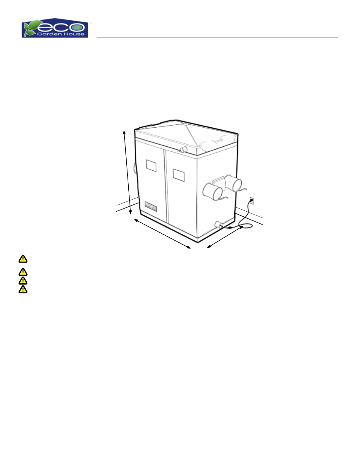
88” x 72” x 48” (1.8m x 1.2m x 2.2m)
Thank you for purchasing the Eco Garden House indoor greenhouse. Please read these
instructions thoroughly before assembling or using the Unit. The terms and conditions
contained in this Assembly Instruction Guide are the only terms which govern the sale of
the unit by The Plastics Group, Inc (TPG). and the direct or indirect use of the unit by you,
your representative, or any third party. By assembling or otherwise using the unit, you
accept and agree to be bound and abide by the terms and conditions contained herein.
The Plastics Group, Inc.
7409 S. Quincy St. Willowbrook IL 60527
1.888.449.3326
48”
(1.2m)
72”
(1.8m)
88”
(2.2m)
www.EcoGardenHouse.com
Check Out Our Site for:
• Video Assembly Guide
• Customer Support
• Join the Indoor Greenhouse
Community
Eco Garden House Assembly Guide Page 2
Important Eco Garden House information: READ ENTIRE ASSEMBLY GUIDE PRIOR TO ASSEMBLY OR
USE. FAILURE TO READ ENTIRE ASSEMBLY GUIDE PRIOR TO ASSEMBLY OR USE MAY RESULT IN INJURY
AND PROPERTY DAMAGE!
• Assemble at nal location. Unit will be able to slide short distances to nal location (Unit cannot be slid
once lled with water).
• DO NOT stand on tank during assembly.
• For easier installation and personal safety, it is recommended that two people install this product.
• Verify that Unit is disconnected from all power sources prior to assembly.
Determining Your Location
Eco Garden House Dimensions
Tools Required
Location Needs
Possible Tools Needed
Accessories Needed
• Make sure that you have measured the nal location for your Eco Garden House (length, width, & height).
• A level oor is required for the placement of the tanks due to liquid water contents.
• #2 Phillips Screwdriver
• Wire Cutter
• Step Stool
• Crescent Wrench
• Level
• Flat Head Screwdriver (Small)
• Space to t 72 ” x 48 ” x 88”
(1.8m x 1.2m x 2.2m)
• Air Ventilation
• Access to Water Supply
•Control Panel Access
•Back Access
•Power Plug (For 110V)
•Minimum of 48” x 88” (1.2m x
2.2m) at surface for assembly
•Recommended 2’ (.6m) spacing
between unit and wall
• Drill with 1/8” bit
• Rubber Mallet
• 4’ (minimum) Extension Cord for the Controller
•4’ (minimum) Extension Cord for the Water Pump
•Standard 3/4” female tting Garden Hose with enough length to connect drainage tank to drainage area
Be sure to remove all items from the box. Verify all pieces before assembly.
72”
(1.8m)
88”
(2.2m)
48”
(1.2m)
www.EcoGardenHouse.com
Check Out Our Site for:
• Video Assembly Guide
• Customer Support
• Join the Indoor Greenhouse
Community

Eco Garden House Assembly Guide Page 3
STOP
For faster resolution call: 1.888.449.3326
Or visit our website: www.EcoGardenHouse.com
In Case of Missing Parts: Please Do Not Return to Store!
Eco Garden House Assembly Guide Page 4
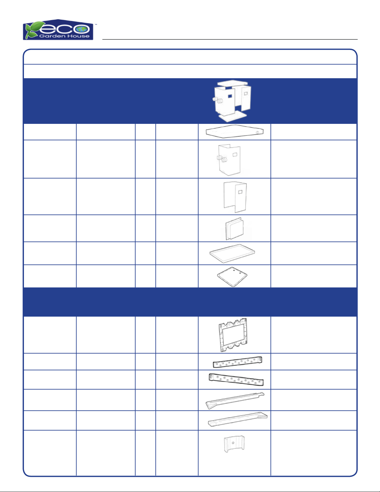
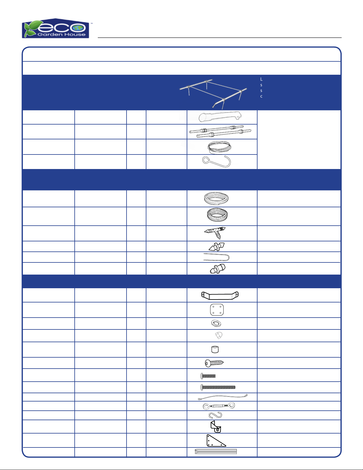
Included Components
Tent Shroud
Frame Assembly
(1)
(1)
SHR601011 Three layer Fabric, adhesive,
Mylar Tent covering with
various ttings
Note: There will be small holes in the
frame, this is due to the manufacturing
process, they will not interfere with
the integrity of the structure.
Part
Kit Qty. Part # Reference Description
(4)
(2)
(2)
(3)
(3)
(1)
(1)
(1)
(2)
(1)
(1)
Shroud Top
Left Side Shroud
Right Side Shroud
SHR601012
BRA601043
Shroud Tray
Control Cover Shroud
4” x 4”Black Shroud
Swatch
Side Wall Panel Eco-Frame
Assembly
Eco-Truss C
Eco-Truss D
Eco-Beam B
Eco-Beam A
Roof Truss Male
Section
Roof Truss Female
Section
Support Beam Male
Section
Support Beam Female
Section
(8)Metal Stampings (Component comes pre-installed
on the frame assembly)
(Components comes attached to
Left and Right Shroud with hook
and loop fasteners)
(Located in Drip Kit Pack)
Eco Garden House Assembly Guide Page 5
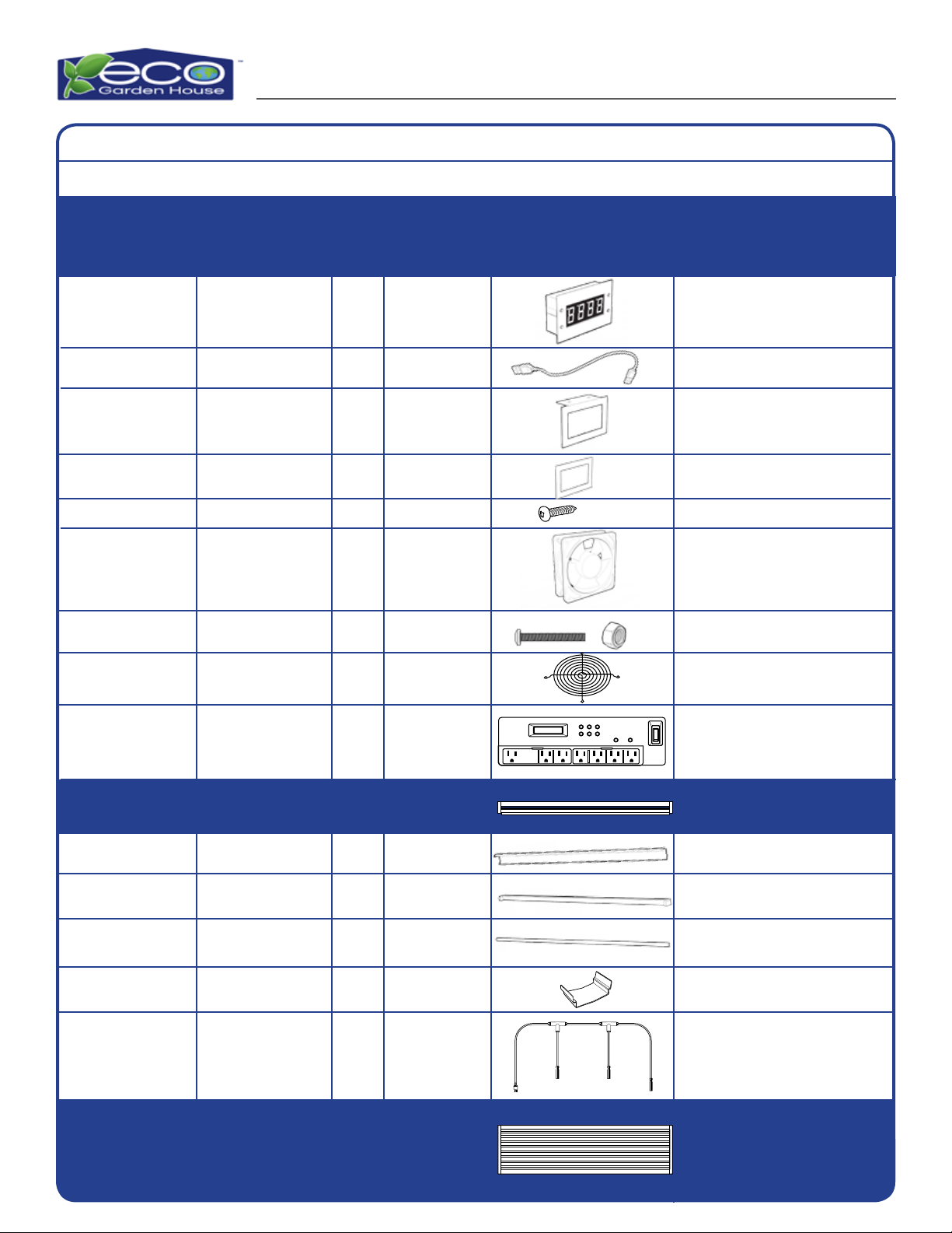
Fan/Digital Display Kit
Metal clips
DIS601014
(1)
Thermal Control Unit
USB Power Supply
Cord
Thermal Control
L-Bracket
Shim Spacer
Screw
Fan
Fan Grills
Included Components (Cont.)
(8)
(4)
(4)
(4)
(2)
(2)
Control Panel CON601010(1)
(1)
(1)
(1)
(1)
(4)
7, 110 volt outlets on two separate
timing circuits with two (2) “always
on” USB power ports with digital
programming and surge protection.
24” Power Cord
High Speed 120mm USB Fans
Pre-installed on Fan
Pre-installed to Fan.
120mm
Reector
Single Bulb Light
Unit
46 inch
Fluorescent Bulb
(4) High output full
spectrum T5 vertical
side light (4 Bulb)
LIG601012
(4)
Bulb T5 xture 1bulb (4)
(1 unit) High output
full spectrum T5
horizontal side light
(8 Bulb)
LIG601013
(8)
Bulb
xture
T5 xture 8-Bulb Overhead
Light Unit
Part
Kit Qty. Part # Reference Description
(1)
Power Cord
Nuts, Bolts (8 each)
Eco Garden House Assembly Guide Page 6
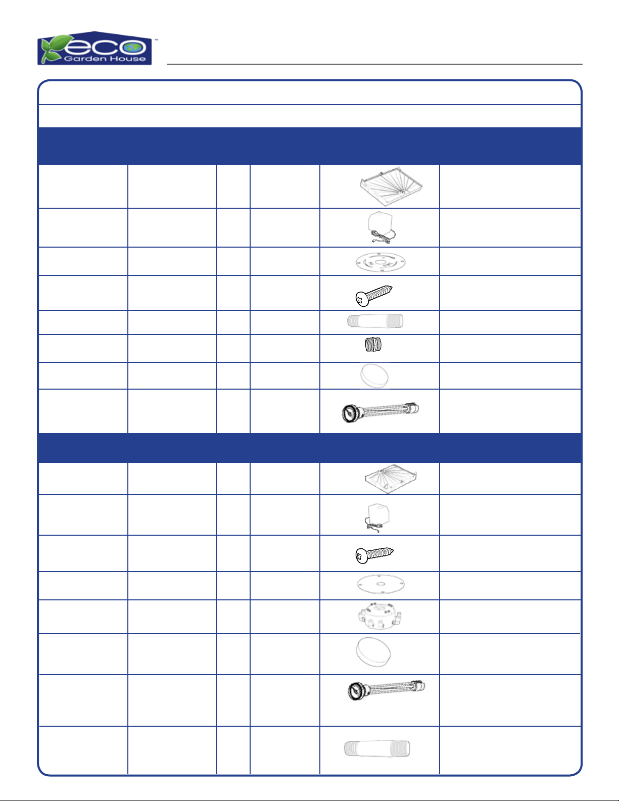
Included Components
Water Pump
Water Sump Pump
8 Way Manifold
3” Nipple
3/4” MPT Garden
Hose tting
PUM601018
PUM601018
FIT601025
FIT601026
FIT601022
(1)
(1)
(1)
(1)
(1)
110 Volt low head (approx. 4 feet) low
pressure pump (Component comes
pre-installed in freshwater tank)
110 Volt low head (approx. 4 feet)
low pressure pump (component
already installed in Gray water Tank)
“8”way swivel end manifold with in-
tegral lter, adjustable ow controls
3 inch plastic gray nipple
3/4” MPT Garden Hose tting
Fill Cap, Freshwater
Blue
Water Level Gauge
& Grommet
Fill Cap, Drainage
Grey
Water Level Gauge
& Grommet
(1)
(1)
(1)
(1)
(1)
(1)
CAP601021
CAP601028
CAP601040
CAP601040
P41420
P41420
Soft plastic water tank caps, Blue/
Purple for freshwater
Soft plastic water tank caps, Grey
for drainage
Drainage Tank Kit All parts come pre-installed in
the gray water tank
SS Drain Plate,
Freshwater
SS Drain Plate, Drain
Pla601016
PLA601023
(1)
(1)
Stainless Steel 18 gauge pump
mounting plate, laser cut
Stainless Steel 18 gauge pump
mounting plate laser cut
3” Nipple FIT601026
(1) 3 inch plastic gray nipple
NOT POTABLE
WATER
(1)Gray water
Tank
(1)
Freshwater
Tank
Eco-Tank E
Eco-Tank F
Part
Kit Qty. Part # Reference Description
SS Screws SCR601032(4) Pre-installed Screws used to mount
the SS pump mounting plates to
the tank’s structure members
SS Screws SCR601032(4) Pre-installed Screws used to mount
the SS pump mounting plates to
the tank’s structure members
All parts come pre-installed in
the freshwater tank
Freshwater Tank Kit
Eco Garden House Assembly Guide Page 7
Included Components (Cont.)
Hardware Kits
Zip Ties
Washers
KIT601042
Eco-Plate
KIT601034
KIT601034
KIT601034
KIT601034
KIT601034
KIT601041
KIT601041
KIT601041
KIT601042
KIT601042
Self Tapping Screws
Cap Nuts
Spacers
Cross Support Wires
Hook/ Hook Turnbuckles
S-Hooks
Controller Corner
Brackets
Triangular Support
Bracket- Gray
(1)
(24)
(34)
(16)
(4)
(2)
(2)
(2)
(2)
(2)
4 count 21” 50 lb. test
Attached to Cross Support Wires
Light Height
Adjustment Assembly LIG601015
(1)
Light raise/lower adjust system of two (2)
steel bars, IM handle with integral return
spring, pulleys/bobbins, pin, screws,
cordage, and“J” hooks assembled and
wrapped in cardboard sleeve
IM handle
Light Adjustment Bars
Cordage
“J” Hooks
Drip Supply Kit KIT601020
(1) Pre-bagged kit of; 25 feet of supply tubing,
30 feet of 6”spacing weeper tubing, 10
“Tees”, 10 stakes, 10 end plugs
Packaged in the Drip Supply Kit
Black Supply Tubing
(25 ft)
Brown Weeper Tubing
(30 ft) (6” spacing)
1/4” Barbed Tees
1/4” Transfer Barb
Stakes
1/4” End Plugs
(1)
(2)
(1)
(1)
(1)
(8)
(10)
(10)
(10)
(10)
Part
Kit Qty. Part # Reference Description
Pre-assembled
(2)
(8)
Plastic Plates
Stainless Steel
U-Brackets
KIT6010341/4”-20 Bolt 5” (10)
KIT6010341/4”-20 Bolt 1.75” (6)

Eco Garden House Assembly Guide Page 8
WARNINGS
1. A level oor is required for placement of the tanks due to the liquid water contents. The oor must be able
to support loads up to 125 lbs per square foot and 1,000 lbs total load for the entire unit (this includes
approximately 500 lbs. of additional load required for planting).
a. The Floor Tanks provide approximately 125 lbs per square foot of support for planting.
b. The Roof Truss members support a maximum total weight of 40 lbs (no more than 10 lbs
maximum per truss of hanging weight).
c. A combined 1,000 lbs Maximum Total Unit Load Capacity, including all water/liquid,
hanging and stationary loads inside of the unit, and anyone working around the unit.
2. Do Not mix old and new batteries
3. Do Not mix alkaline, standard, or rechargeable batteries
4. WARNING USE CAUTION. Edges may be sharp. Improper handling or use may result in personal injury or
death. Always wear work gloves, eye protection, and long sleeves when assembling or performing any
maintenance on the unit.
5. Before starting assembly, please read through the assembly instructions. Remove all of the items from
the box and arrange them in an orderly manner. Make sure to use a“Team Lift”with two (2) people
when removing the large plastic tanks, the main horizontal light unit, and any other large items from the
packaging. Take care that some items include multiple parts/components, all of which are needed for
correct assembly.
6.This unit is designed and intended to be an “Indoor Unit”only! This product is not designed for exposure to
the outside environment.
7. The included power strip/timer/controller is equipped with a“ground fault” detection system. It will indicate
when the unit is not correctly connected to a proper ground. This grounded connection is mandatory and
required for safe and proper operation of the unit. Do not bypass these grounded connections! Ensure any
circuit not providing the proper ground and voltage supply is repaired or replaced immediately!
8. The included Reective Shroud/Tent must never be exposed to direct or indirect contact with an open ame,
hot/heating electrical devices.
9. This unit is not a playhouse or a toy; it is designed, engineered and manufactured for the purpose of Indoor
Greenhouse functions and is not to be used for any other purpose.
10. All of the above and included “warnings” and “limitations” within this Assembly Instruction Manual must
be strictly followed. In the event that the terms and conditions contained herein are not strictly followed,
any warranty provided herein shall be void and you agree to release TPG from any liability hereunder or
otherwise related to the Unit and any claim, demand, suit, settlement, cause of action, judgment, liability,
loss, or expense arising out of or related to in whole or in part, the Unit and the use or misuse thereof.
Limited 1 Year Warranty
TPG warrants to you that for a period of one (1) year from the date of purchase of the Unit as evidenced by a
dated, non-faded, legible original purchase receipt (“Warranty Period”), that under normal use and service,
such Unit will materially conform to the specications set forth in this Assembly Guide and will be free from
material defects in material and workmanship. Without limiting the foregoing, Unit defects or damage caused
or arising in whole or in part by or from (i) improper, incorrect, or inappropriate handling, assembly, storage,
maintenance, or use, (ii) neglect, (iii) commercial use, or use other than for household purposes, and (iv)
alteration, including without limitation painting or coating are excluded from this limited warranty. EXCEPT
FOR THE LIMITED WARRANTY SET FORTH IN THIS PARAGRAPH, TPG MAKES NO WARRANTY WHATSOEVER WITH
RESPECT TO THE UNIT, INCLUDING ANY WARRANTY OF FITNESS FOR A PARTICULAR PURPOSE; OR WARRANTY
AGAINST INFRINGEMENT OF INTELLECTUAL PROPERTY RIGHTS OF A THIRD PARTY; WHETHER EXPRESS OR
IMPLIED BY LAW, COURSE OF DEALING, COURSE OF PERFORMANCE, USAGE OF TRADE OR OTHERWISE. IN
THE EVENT WARRANTIES EXIST AT LAW THAT MAY NOT BE DISCLAIMED, YOU AGREE THAT SUCH WARRANTIES
SHALL BE LIMITED IN DURATION TO THE WARRANTY PERIOD.

Eco Garden House Assembly Guide Page 9
Products manufactured by a third party (“Third Party Product”) may constitute, contain, be contained in,
incorporated into, attached to or packaged together with, the Unit. Third Party Products are not covered by the
TPG limited warranty. For the avoidance of doubt, TPG MAKES NO REPRESENTATIONS OR WARRANTIES WITH
RESPECT TO ANY THIRD PARTY PRODUCT, INCLUDING ANY WARRANTY OF MERCHANTABILITY; WARRANTY
OF FITNESS FOR A PARTICULAR PURPOSE; WARRANTY OF TITLE; OR WARRANTY AGAINST INFRINGEMENT OF
INTELLECTUAL PROPERTY RIGHTS OF A THIRD PARTY; WHETHER EXPRESS OR IMPLIED BY LAW, COURSE OF
DEALING, COURSE OF PERFORMANCE, USAGE OF TRADE OR OTHERWISE. TPG shall not be liable for a breach of
warranty unless: (i) you give written notice of the defect, reasonably described, to TPG within ten (10) days of
the time when you discover or ought to have discovered the defect; (ii) TPG is given a reasonable opportunity
after receiving the notice to examine such Unit and you (if requested to do so by TPG) return such Unit to
TPG at your cost for the examination to take place there; and (iii) TPG reasonably veries your claim that the
Unit is defective. With respect to any such Unit during the Warranty Period, TPG shall, in its sole discretion,
either: (i) repair or replace such Unit (or the defective part) or (ii) credit or refund the price of such Unit at the
pro rata rate reecting applicable depreciation and use provided that, if TPG so requests, you shall, at your
expense, return such Unit to TPG. IN NO EVENT SHALL TPG BE LIABLE FOR ANY CONSEQUENTIAL, INDIRECT,
INCIDENTAL, SPECIAL, EXEMPLARY, OR PUNITIVE DAMAGES, LOST PROFITS OR REVENUES OR DIMINUTION IN
VALUE, ARISING OUT OF OR RELATING TO ANY BREACH OF THE TERMS OF THIS ASSEMBLY GUIDE, WHETHER
OR NOT THE POSSIBILITY OF SUCH DAMAGES HAS BEEN DISCLOSED IN ADVANCE BY YOU OR COULD HAVE
BEEN REASONABLY FORESEEN BY YOU, REGARDLESS OF THE LEGAL OR EQUITABLE THEORY (CONTRACT, TORT
OR OTHERWISE) UPON WHICH THE CLAIM IS BASED, AND NOTWITHSTANDING THE FAILURE OF ANY AGREED
OR OTHER REMEDY OF ITS ESSENTIAL PURPOSE. IN NO EVENT SHALL TPG’S AGGREGATE LIABILITY ARISING
OUT OF OR RELATED TO THIS AGREEMENT, WHETHER ARISING OUT OF OR RELATED TO BREACH OF CONTRACT,
TORT (INCLUDING NEGLIGENCE) OR OTHERWISE, EXCEED THE TOTAL OF THE AMOUNTS PAID TO TPG FOR THE
APPLICABLE UNIT.
WARNINGS: “Third Party Products” included with the Unit:
Eco Garden House Assembly Guide Page 10
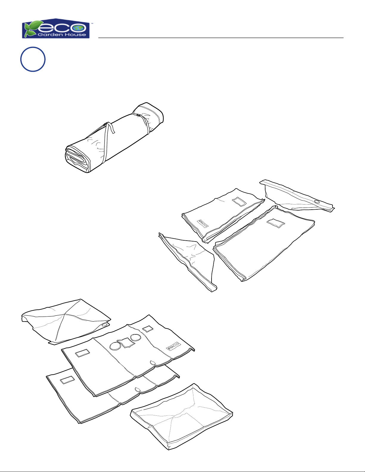
1Unwrap and Unzip Eco Garden House Shroud
Loosen and remove the
straps from the shroud.
Unroll/unfold shroud and
unzip into separate pieces.
Contents: Roof/ Top
Shroud, two Side Shrouds,
and a Shroud Tray. Set
aside everything but the
Shroud Tray.
TOP
LEFT
RIGHT
TRAY
Eco Garden House Assembly Guide Page 11
Eco Garden House Assembly Guide Page 11
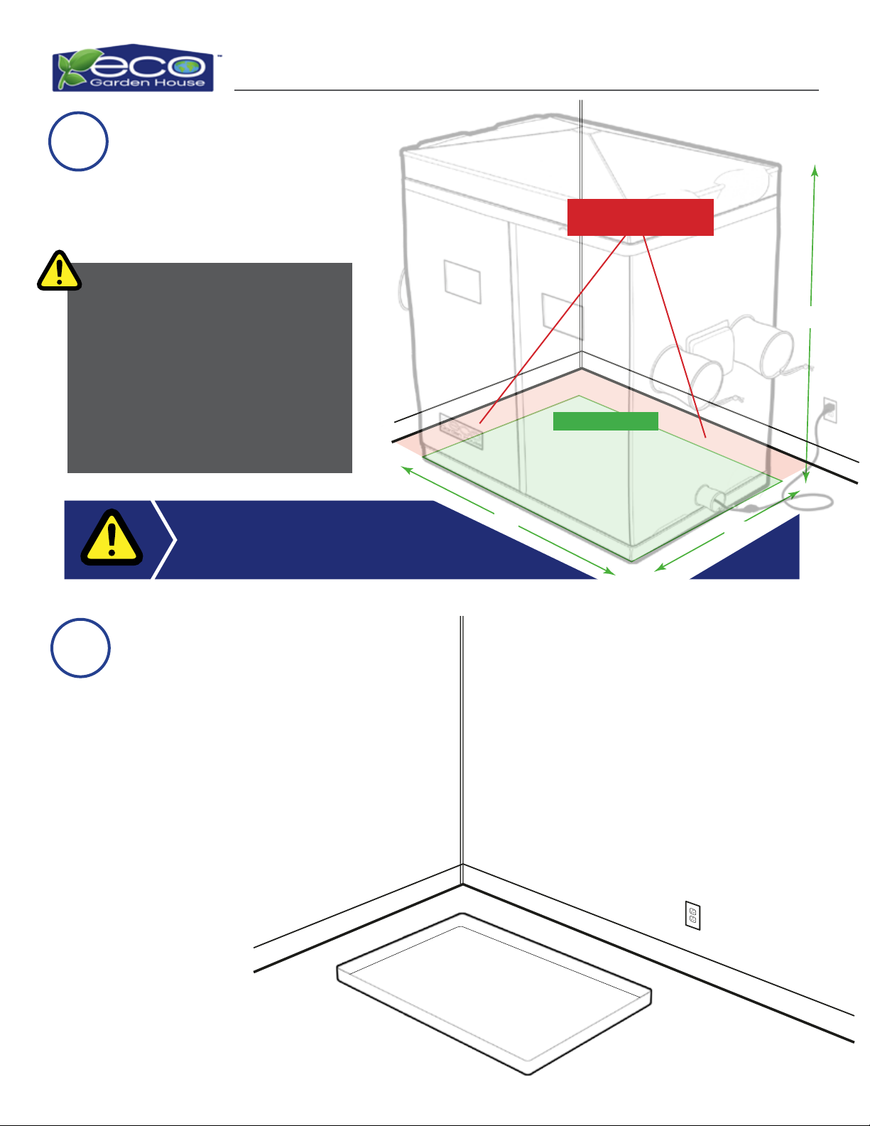
3
Select a location. Location
must be larger than (88” x
72” x 48”) and within 4’ of a
110v outlet.
2
Leave adequate space between the
walls and Eco Garden House for easy access.
This will be the nal location for the fully
assembled unit. Unit will only be able to
slide slightly for nal positioning. Please
consider the following:
· Electrical Location
· Air Ventilation
· Water Supply and Drain
·Control Panel Access
·Back Access
Place “water tight” Shroud
Tray in desired nal position.
Floor and Tank Assembly
Place Shroud Tray
72”
88”
Suggested 2’ space
between unit and wall
Footprint of unit.
48”
Eco Garden House Assembly Guide Page 12
Eco Garden House Assembly Guide Page 12
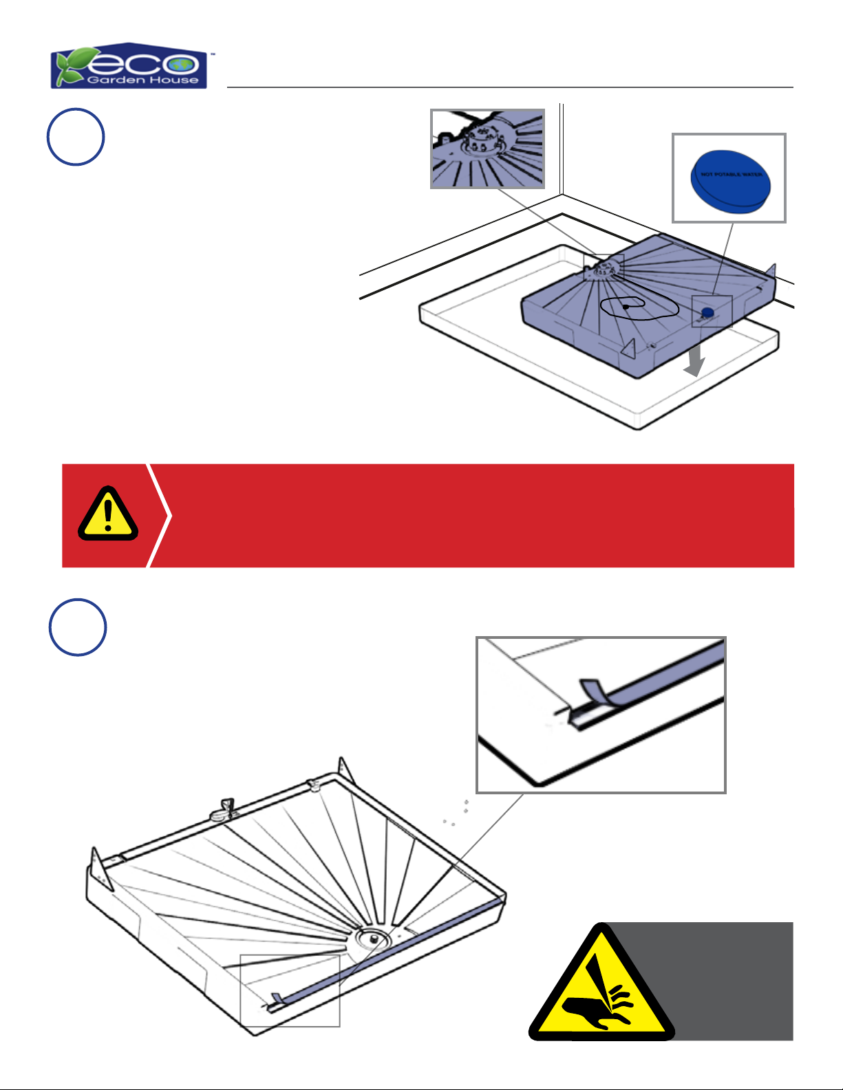
5
Place the Freshwater Tank in
the Shroud Tray on desired
control panel side.
4
VERY IMPORTANT: The Freshwater Tank will need power supplied to it. Position
it on the same side that you plan to install the Control Panel, Fans, & the Thermal
Control Unit. You can dierentiate the Freshwater Tank by the 8-Way Manifold
and the Blue Cap.
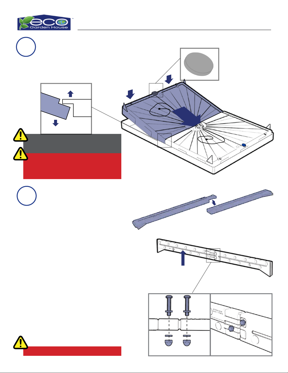
Remove the backing o of the
adhesive strip on the top of
the Gray Water Tank.
Install Freshwater Tank
Peel o Backing to Expose Adhesive on Gray Water Tank
Control Panel Side
Blue Cap on
Freshwater Tank
8-Way Manifold
USE CAUTION:
Triangular Brackets
attached to both
Tanks have
SHARP EDGES.
Eco Garden House Assembly Guide Page 13
Slip nose/ drain carrier end of Gray Water
Tank under freshwater tank during
install. DO NOT bunch adhesive.
DO NOT over-tighten Bolt!
Two People are needed to install the
Gray Water Tank.
Control Panel Side
Place the Gray water Tank in
the Shroud Tray next to the
Freshwater Tank.
6
7
Install Gray Water Tank
Connect one (1) Male Support
Beam Section to one (1) Female
Support Beam Section on a at
surface.
Secure Male and Female Support
Beam Sections Together: Gather
two (2) 1.75”Bolts, four (4)
Washers, and two (2) Cap Nuts.
Twist a Bolt with Washer into the
top Female Support Beam Foot
Section connecting both Support
Beams. Attach one Washer and Cap
Nut and use a crescent wrench to
secure the Bolt on the cord track
side of the Beam. Repeat the same
steps to secure the center of the
bottom Female foot to the Male
Support Beam. Set aside for use in
Step 16.
Assemble Upper Rear Support Beam
Top Side
Bottom Side
Tilt and Tip
Gray Cap on Gray
Water Tank
Cord track
Top View
Eco Garden House Assembly Guide Page 14
LOGO
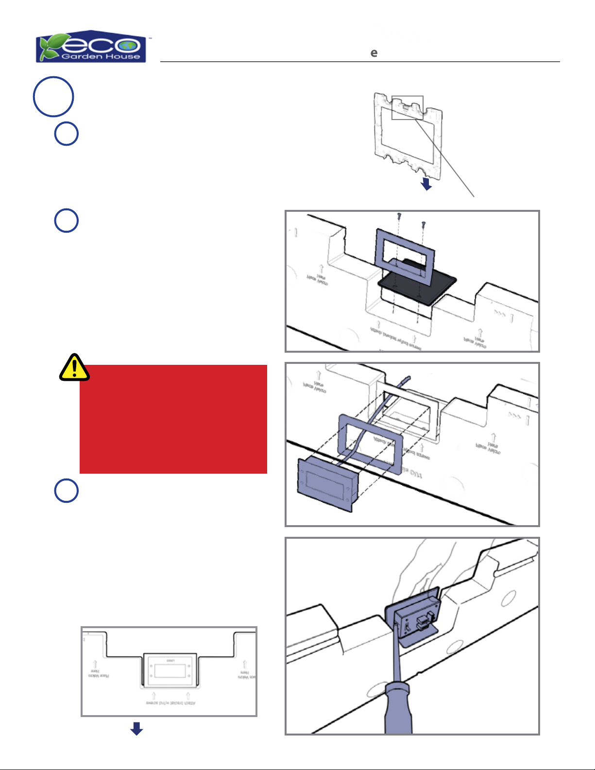
Locate the Fan Kit Box with the
“L”Bracket, Thermal Control
Unit, and the two (2) Screws.
Locate the 4”x 4”Black Shroud
Swatch (in Drip Kit package).
Mount the “L” Bracket with the
4” x 4” Black Shroud Swatch on
top (shiny side touching the
Side Wall Section) onto one of
the Wall Sections. Ensure it is
facing the side that says,“This
Side Out.”This assembly will
designate the Control Panel
Side of the unit.
Snap the Shim Spacer and the
Thermal Control Unit into the
“L” Bracket. When installing,
the text on the display should
be upside down. A screwdriver
may be needed to squeeze the
side tabs to lock in place. (Shim
Spacer may not be necessary.)
8Install Fan / Thermal Control Unit
Top Side
Control Panel
Top Side
Be sure you mount the Thermal Control
on the top section of the cross with logo
text properly oriented.
The screws will be installed using the
designated dimples.
DO NOT remove plastic from the sensor.
A
B
C
Eco Garden House Assembly Guide Page 15
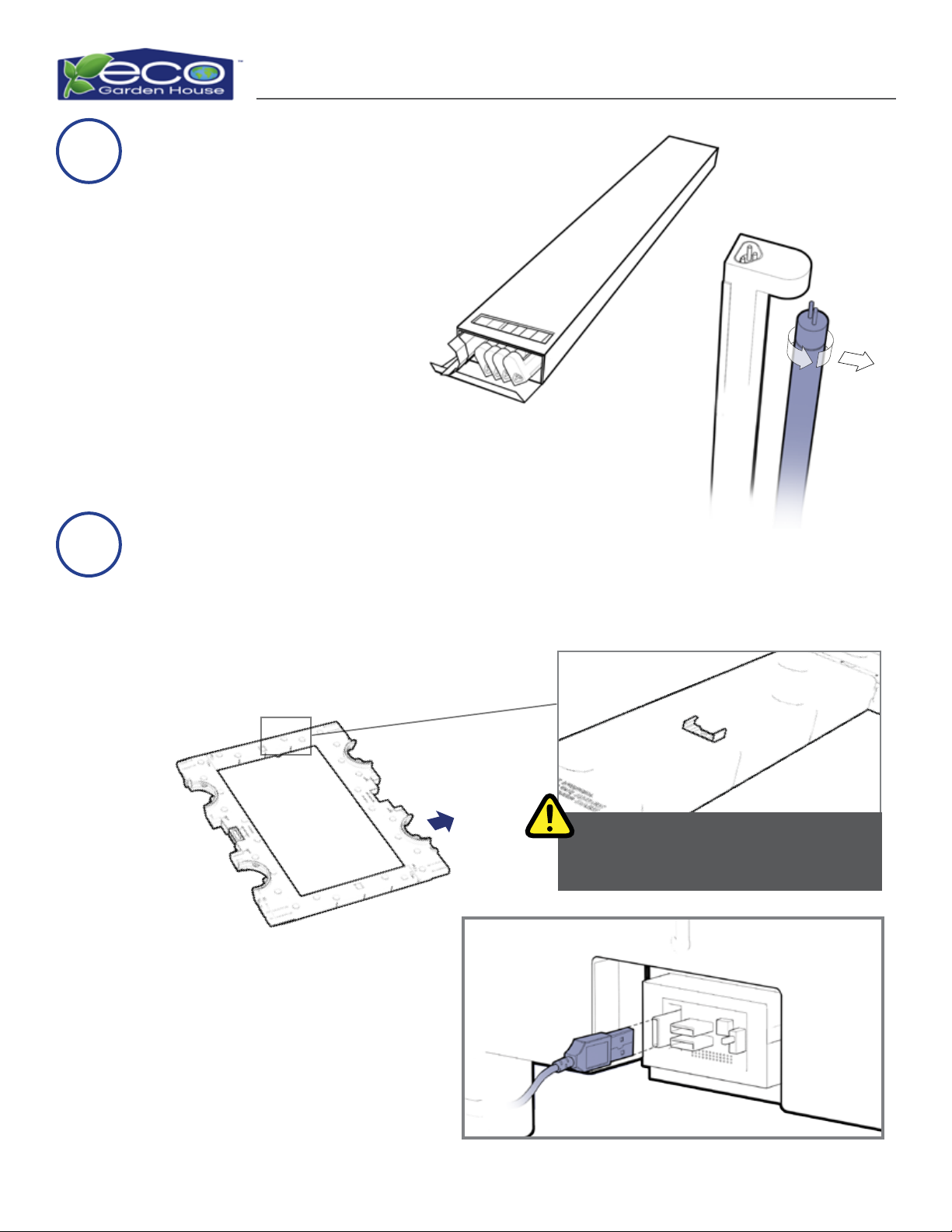
Place the Wall Section with
the Thermal Controller down
on the oor with the metal
stampings facing up.
10
Plug the USB Power Supply
Cord into the back of the
Thermal Control Unit.
Unpack the four (4) pack of
the Single Bulb Light Units.
Remove the bulb from each
of the light units by twisting.
Keep the foam on the bulbs
for protection, and safely set
them aside.
9Unpack Single Light Bulb Units
Ensure the metal stamping is facing up.
Top Side
Flip Over Control Panel Side Wall Panel & Attach the USB Power Supply Cord
Control Panel Side
Eco Garden House Assembly Guide Page 16
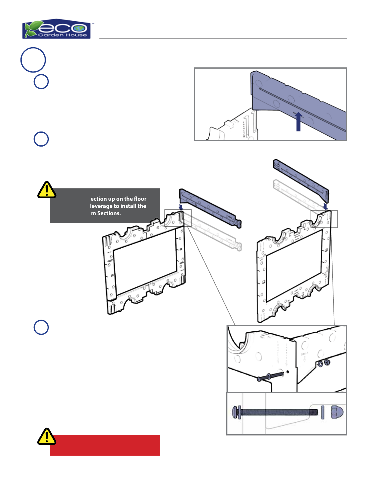
Stand Wall Section up on the oor
to get more leverage to install the
Support Beam Sections.
Female Support Beam Section
Male Support Beam Section
Gather a Male and Female Support
Beam Section and two (2) Wall
Sections. Do not use the Wall Section
with the Thermal Control Unit.
Attach both the Male and Female
Support Beam Sections to separate
Wall Sections.
Gather two (2) 5”Bolts, four (4)
Washers, and two (2) Cap Nuts.
Slide a Washer onto a Bolt. Install
the Bolt through both the Wall
Section and the Support Beam.
Slide a Washer onto the other
side of the Bolt and secure with a
Cap Nut. Use a crescent wrench to
tighten. Repeat steps to attach the
remaining Support Beam to the
remaining Wall Section.
11 Attach Center Support Beams to Wall Sections
DO NOT Over-tighten Bolts!
A
B
C
Cord Track Facing In
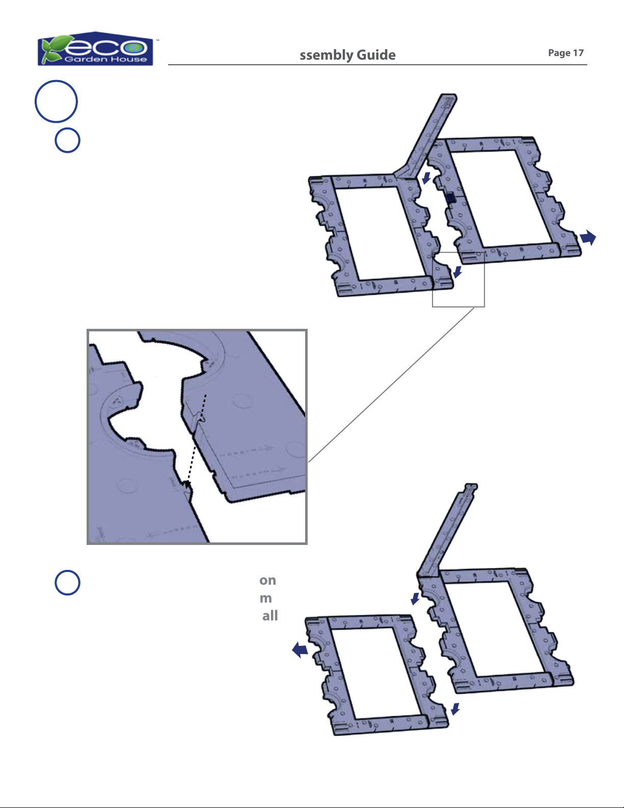
Eco Garden House Assembly Guide Page 17
Thermal Control Wall Panel
Female Support Beam Section
Place all four (4) Wall Section
pieces with the Metal
Stampings face up on a at
surface. Attach the Control
Panel Wall Section to the
Wall Section with the Female
Support Beam Section.
Attach the Wall Panel Section
with the Male Support Beam
Section to the remaining Wall
Section.
12 Assemble Side Wall Panels
A
B
Male Support Beam Section
Top Side
Top Side
Eco Garden House Assembly Guide Page 18
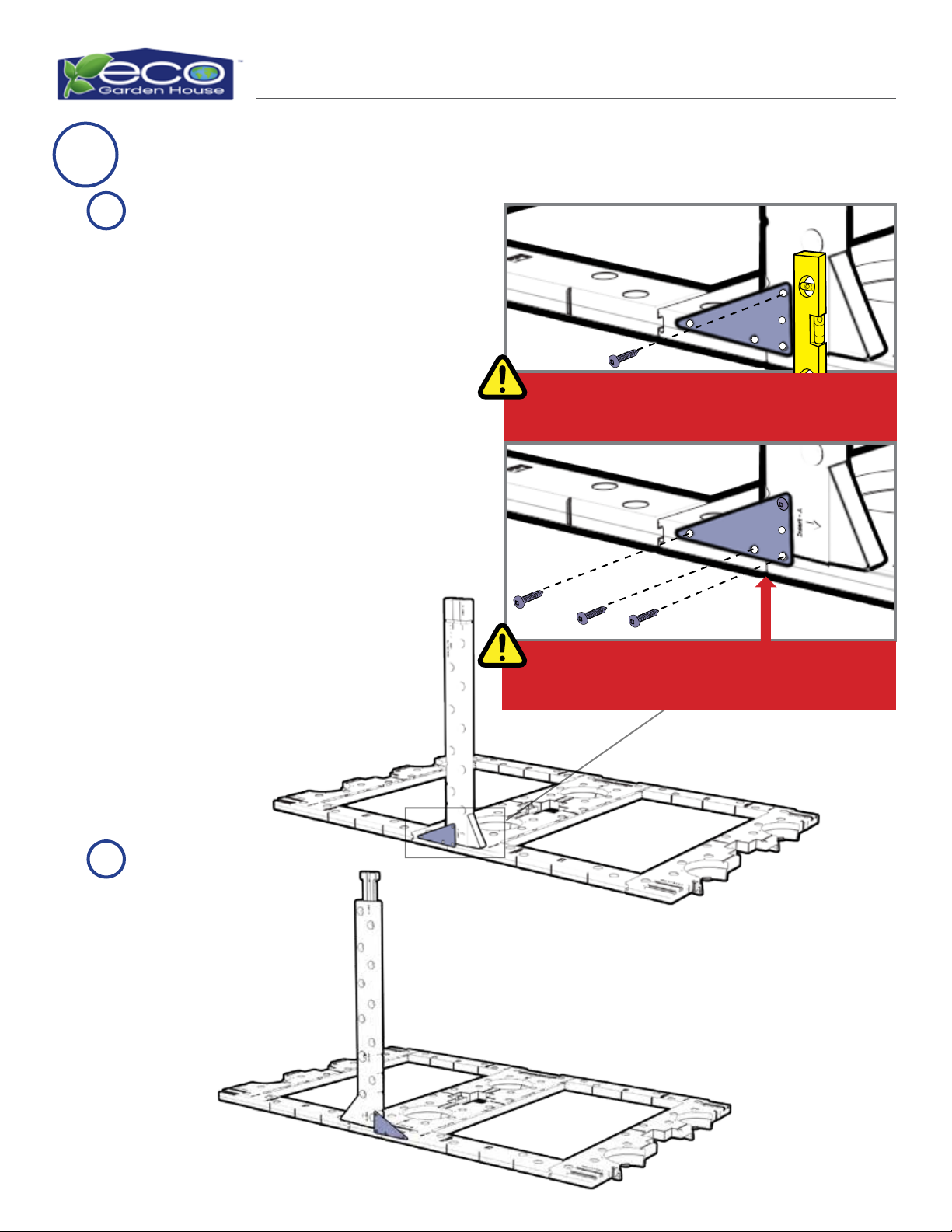
Male Support Beam Section
13 Attach Support Brackets to Middle Support Beams and Wall Panels
Gather the two (2) Triangular
Support Brackets. Position one (1)
Bracket with the shortest side of
the triangle on the Middle Support
Beam and the three holes on the
Wall Panel. Line up the longest
three hole side of the Bracket to
the parting line on the Wall Panel
and ensure the two holes closest to
each other are straddling the two
Wall Panel Sections. Screw into the
Middle Support Beam use a level
to ensure it is completely vertical
before installing the three (3)
remaining screws to the Wall
Panel. The middle hole on the
shortest side will remain open
for use in Step 17.
Repeat Step A on the
remaining Wall Panel.
A
B
TOP SIDE
TOP SIDE
Ensure the two holes straddling the Wall Panel
Sections are evenly spaced.
Use a level to ensure the Support Beam and the
Triangular Bracket are completely level.
Eco Garden House Assembly Guide Page 19
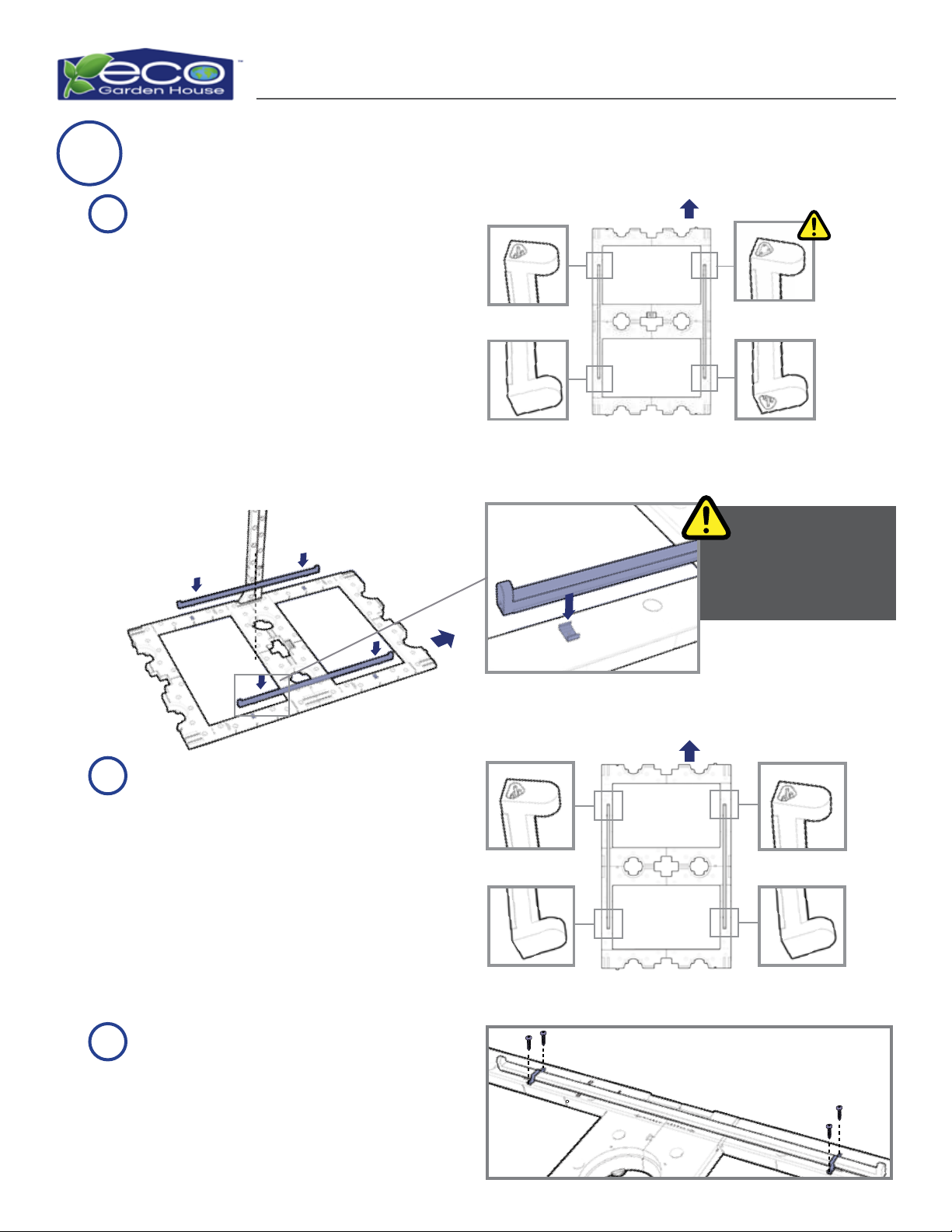
14
Snap the remaining two (2)
Single Bulb Light Units with the
open male plugs on the top side
into the left and right metal
stampings on the Side Wall
Panel without the Thermal
Control Unit.
Install Single Bulb Light Units
Gather eight (8) U-Brackets. Place
two (2) U-Brackets on each Single
Bulb Light unit, aligned with the
Metal Stampings that the Single
Bulb Unit snapped into. Attach
each U-Bracket with two (2) screws.
Control Panel
Female Plug
Male Plug
Male Plug
Top Side
Male Plug Male Plug
Male Support
Beam Wall Panel
Top Side
Top Side
A
B
C
Ensure the Single
Bulb Light Units are
centered on the Wall
Panels.
Locate the one (1) Single Bulb
Light Unit that has open female
and male plugs, and snap female
plug side up, into the metal
stampings on the right side of
the Control Panel Side Wall. Snap
another Single Bulb Light Unit
onto the metal stampings on the
left side of the Control Panel Side
Wall, with the open male plug on
the top side.
Eco Garden House Assembly Guide Page 20
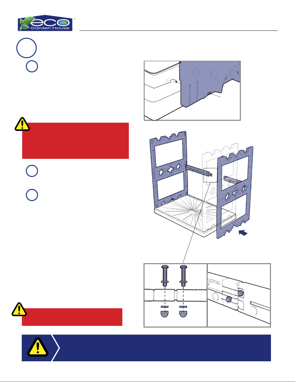
Top View
Slide both of the Side Wall Panels
with their top sides up and the
Support Beam Sections at the
back of the unit (Refer to diagrams
in Step 14) onto the tanks. Ensure
the Single Bulb Light Units are
facing inside the unit.
Attach the Male and Female
Support Beam Sections.
15 Attach Side Wall Panels
DO NOT stand on the tank during assembly.
The Side Wall Panel with the Thermal
Control Unit must be attached to the
Freshwater Tank.
Control Panel Side
Freshwater Tank
Gray Water Tank
It is recommended that two people are used to connect and hold Side Walls in
place while connecting the Center Support Beam.
DO NOT over-tighten Bolts!
Secure Male and Female Support
Beam Sections Together: Gather
two (2) 1.75”Bolts, four (4)
Washers, and two (2) Cap Nuts.
Twist a Bolt with Washer into the
top Female Support Beam Foot
Section connecting both Support
Beams. Attach one Washer and
Cap Nut and use a crescent
wrench to secure the Bolt on
the cord track side of the Beam.
Repeat the same steps to secure
the center of the bottom Female
foot to the Male Support Beam.
A
C
B
Popular Lawn And Garden Equipment manuals by other brands

Plow & Hearth
Plow & Hearth 54186 Assembly instructions

FLINQ
FLINQ FQC 8155 user manual

Craftsman
Craftsman 316.792570 Operator's manual

Echo
Echo POWER PRUNER DPPT-2600H Operator's manual

Gude
Gude GPF 300 Translation of the original instructions

PHARMTEC
PHARMTEC Elite Cedar PLANTER 3636 Assembly instructions


