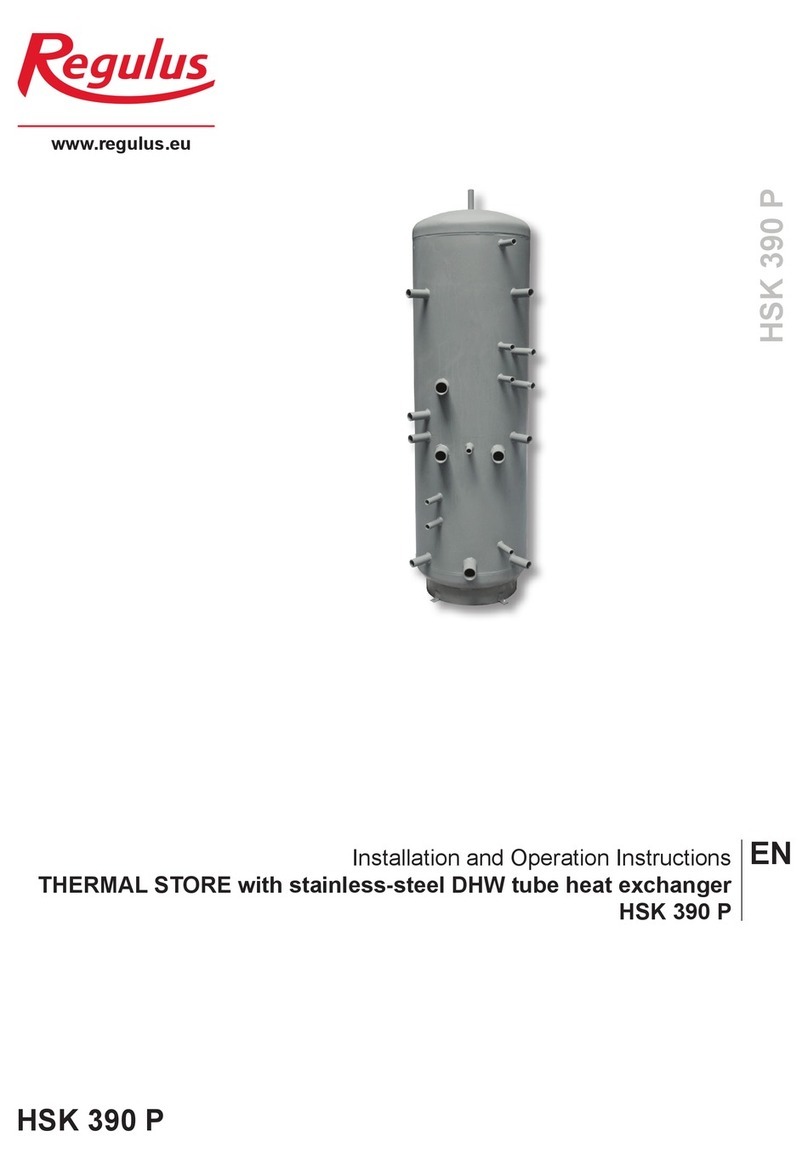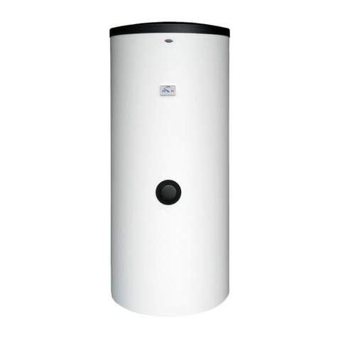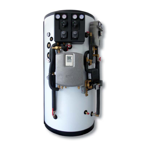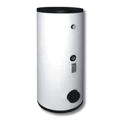
Code
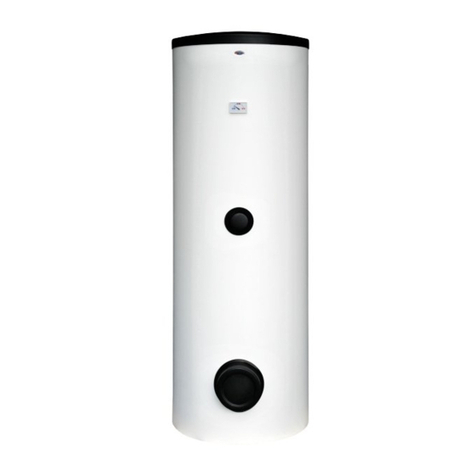
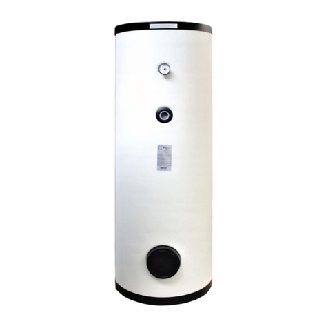
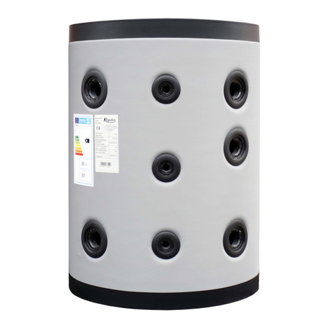
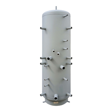
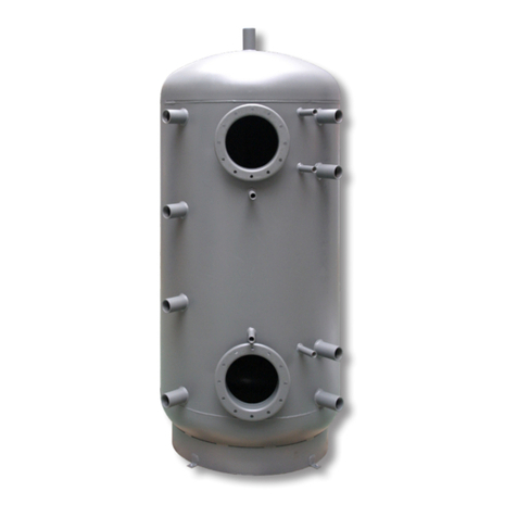
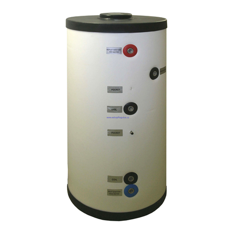
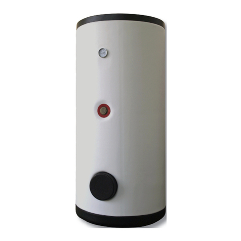
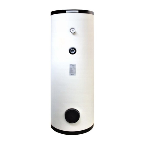
Thermal store PS 600 ES+ PS 900 ES+ PS 1100 ES+
Tank code 15527 15530 15956
Insulation code (accessor.) 16333 16340 16348
Application
Storage and subsequent distribution of thermal energy from solid-fuel boilers, heat pumps or other heat sources.
Energy efficiency data (as per EC Regulation No. 813/2013)
PS 600 ES+
w. insulation
PS 900 ES+
w. insulation
PS 1100 ES+
w. insulation
Energy efficiency class - - -
Standing loss 101 W 125 W 139 W
Storage volume 560 l 860 l 1037 l
Technical data
Total tank volume 560 l 860 l 1037 l
Max. working temperature in tank 95 °C 95 °C 95 °C
Max. working pressure in tank 3 bar 3 bar 4 bar
Material
Tank material S235JR S235JR S235JR
Dimensions, tipping height, weight
Tank diameter 650 mm 790 mm 850 mm
Tank diameter with insulation 850 mm 990 mm 1050 mm
Tank overall height 1935 mm 1975 mm 2080 mm
Tipping height without insulation 1960 mm 2015 mm 2335 mm
Heating elem. max. length / output 700 mm / 8,2 kW 815 mm / 12 kW 815 mm / 12 kW
Empty weight 62 kg 84 kg 123 kg
Accessories
Insulation code 16333 code 16340 code 16348
El. heating element models ETT-A, C, D, F, G, K, L, M
Thermal store PS 600 ES+ PS 900 ES+ PS 1100 ES+
Tipping height without
insulation
1960 mm 2015 mm 2335 mm
Marking Connection Height [mm] Connection Height [mm] Connection Height [mm]
Heating system
H1 G 6/4" 1935 G 6/4" 1975 G 6/4" 2080
H2 G 6/4" 235 G 6/4" 225 G 6/4" 255
Control and safety
C1 G 1/2" 1510 G 1/2" 1530 G 1/2" 1620
Universal inlet/outlet
U1 G 6/4" 1635 G 6/4" 1655 G 6/4" 1745
U2 G 6/4" 935 G 6/4" 955 G 6/4" 1045
Tank dimensions [mm]
VTank height 1935 Tank height 1975 Tank height 2080
Ø Di Tank diameter 650 Tank diameter 790 Tank diameter 850
Ø De Diam. w. insulation 850 Diam. w. insulation 990 Diam. w. insulation 1050
5 │
4 - Operation
In a thermal store, heating water can be heated up by several heat sources like various types of hot-water boilers,
renewable energy sources or electric heating elements.
The thermal store shall be connected to a heat source through G 6/4” threaded fittings. Connections depend on the
circuits to be connected.
5 - Installation and Commissioning
Installation must meet valid rules and may be done only by qualified staff.
Defects caused by improper installation, use or handling are not covered by warranty.
After the tank is installed and connected to an existing heating system, it is recommended to clean the entire heating
system using a suitable cleaning agent, e.g. MR-501/R or a similar one offered by Regulus.
Anti-corrosion protective liquid for heating circuits should be also used, e.g. MR-501/F.
5.1 - Connection to heat sources
Place the tank on the floor, as close to your heat source as possible. Fit the insulation, cf. Installing Insulation on the
Tank. Connect the heating circuits to inlets and outlets respecting the thermal stratification in the tank. Install a drain
valve at the lowest point of the tank. Install an air vent valve at the highest point of the system. Insulate all the conne-
cting piping.
5.2 - El. heating element installation
The G 6/4“ side tapping is designed to accommodate an electric heating rod. A thermal store can be fitted with an el.
heating rod depending on the tank diameter and rod length. It can be controlled either directly (thermostat-equipped
elements), or by a heating system controller.
Warning: Electric heating elements shall be protected by a safety thermostat.
The installation may be done by qualified staff only.
5.3 - Commissioning
This tank is not designed for DHW heating.
The tank shall be filled up together with the heating system, respecting valid standards and rules. In order to minimize
corrosion, special additives for heating systems should be used. The quality of heating water depends on the quality of
filling water at commissioning, on the top-up water and on the frequency of topping up. This has a strong influence on
the lifetime of heating systems. Poor quality of heating water may cause problems like corrosion or incrustation, esp.
on heat transfer surfaces.
Fill the heating circuits with the appropriate fluids and air-bleed the entire system. Check all connections for leaks and
verify the system pressure. Set the heating controller in compliance with the documentation and manufacturer’s reco-
mmendations. Check regularly proper function of all control and adjustment elements.
