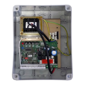
ecogate greenBOX 12 User guide

greenBOX®12
Startup Guide
Updated: May 2019
Intelligent Industrial Ventilation
Ecogate, Inc.
5669 Whitnall Hwy
North Hollywood
CA 91601, USA
Phone: +1-818-506-6016
www.ecogate.com
info@ecogate.com

2. INTRODUCTION & CONTENT
The ECOGATE®System completesdust collecting systems. The greenBOX can control gates
for twelve workstationsand a Variable Frequency Drive (VFD) to adjust fan RPM. In a typical
factory, about half of the machines arenot in use at any given time. The ECOGATE®System
automatically turns onthe vacuum system tomachinesinusewhile turning it off to those not in
use; moreover, it can control (optional) a variable frequency drive toadjust fan RPM. This
generally savesapproximately 55-70% of fan electrical consumption, and active workstations
havebetter suction. Based on thenumber of workstations in operationata giventime, a larger
number of workstations may be connected to the same system. The greenBOX also
automatically maintains minimum air flow toavoid saw dust settling.
Important Warning
Nevertouch the high-voltage terminalsin thegreenBOX. Failure to observe this warning may result in an electrical
shock. Onlyauthorized personnel should be permitted to perform installation, maintenance, inspections, or part
replacement.
Wiring
Begin wiring only after verifying that the power supply is turned OFF. Only qualified personnel
should perform wiring. Failure to observethis warning may result inan electrical shock or fire.
IMPORTANTNOTE:ECOGATE, Inc.doesnotassumeany liabilityregardingthe interpretation of theinformationinthis document.
Theinformationcontained inthisUserandInstallation Guideisarecommendedmethodforinstallingand operatingadustcollectionsystem andis
offered as aguideonly.You are individuallyresponsiblefor the safety anddesignofyourparticular dust collectionsystem. Thismanual may be
modifiedwhennecessarybecauseofimprovementsoftheproduct, modification,orchanges inspecifications.
Your particular systemmust adhere to all rules andregulationssetby federal,stateor localgoverningcodesandrequirements where applicable.
This“User andInstallationGuide” doesnotattempt to describeevery aspectofsafety, implementation,andoperation ofanyparticulardust
collectionsystem.Industrial applications alsoinvolvemanymorevariablesand trade-offdecisions as wellas strictcompliancewithOSHA and
other regulatory agencies.Especiallyimportant is tofollowrules for thecombustibledusthazards; asanintroduction, seehttp://
www.youtube.com/watch?v=3d37Ca3E4fA&feature=player_embedded orvisit CSB -US ChemicalSafety Board at http://www.csb.gov/.
Allterms inthismanual thatareknownto be trademarksor service marksarelistedbelow.Use ofa termin thismanual, whether listedbelow or
otherwise,shouldnot beregardedasaffectingthe validityofany trademark or servicemark.
All rights reserved. Product appearance and specifications are subject to change without prior notice. US Pat. No. 6,012,199; 7,146,677;
other patents pending. greenBOX®,ECOGATE®,and ECOGATE logo are registered trademarks of ECOGATE, Inc.
Thank you for purchasing the
ECOGATE®greenBOX 12control unit.
Read this User Guidethoroughly
beforesystem installation, setup, and
use.
Table of Content:
User Guide..…………….………. 3
Schematic Diagram..….……….. 4
Gate Connection…………..…… 7
VOLT Sensor..………………..... 9
CURRENT Sensor.…………..... 10
Software Installation...…………. 11
PC Software SETUP……...…… 13
PC Software STATUS.….……… 14
PC Software TEST…..….……… 15
PC Software SERVICE...….…… 16
Bypass Switch, Security Input..17,18
Fan On, Off Contactor, VFD.. 19-21
Specifications…………………… 25
Main Board Overview..………….. 23
Troubleshooting………………… 24
Specifications…………………… 25
Service & Support……………… 26

3. greenBOX 12 USER GUIDE
The ECOGATE®System completes dust collecting systems. The greenBOX controls gates at each workstation, starts and stops the
dust collector automatically by using workstation activity sensors. The greenBOX also automatically maintains minimum air flow to
avoid dust settling (if Smart Minimum airflow is set). The power supply to the greenBOX should be connected at all times. The dust
collector will start automatically with the start of any of the workstations.
All the safety and operating instructions in the Ecogate greenBOX 12 User Guide and for the other parts of the ventilation system
(fan, filter, transport) should be read before the product is operated. The dust collecting system (gates, fan, filter, cleaning
mechanisms, transport etc.) can run automatically at any time without warning. Keep hands away from gates because they are
connected to the control unit which can run the gate automatically at any time without warning.
How does automatic mode work?
If you switch any workstation ON, the greenBOX®will leave the appropriate gate open, switch the dust collector ON, and close all
the other gates. Note: some gates on non-operating machinery will remain open to maintain the minimum required air flow in the
duct system and dust collector. Turning ON further workstations will open the corresponding gates.
Similarly, turning workstations OFF will close the appropriate gates (each gate can close with a programmable delay of up to 99
seconds). Upon turning OFF the last operating workstation, the greenBOX®will switch the dust collector OFF (with a
preprogrammed delay of up to 0…99 minutes) and will open all the gates (for security reasons and for system cleaning).
Is the gate open?
To see if the gates are working, start each workstation and monitor indicators on the gate motor housing. The GREEN gate indicator
is ON when the gate is opening (about 5 seconds for 6" gate), the RED gate indicator is ON when the gate is closing (also about 5
seconds for 6" gate).
Troubleshooting
1. If any workstation sensor is active, the yellow indicator "INPUT SIGNAL" on the greenBOX main board will be ON.
2. If any gates (1…12) are open, then the corresponding green indicator "GATE OPEN" (1…12) will be ON to reflect this status.
During the gate movement (to either the open or closed position) the corresponding "GATE OPEN" indicator flashes.
3. "POWER" indicates that a power supply is present at the greenBOX.
4. Whenever the fan should be ON, the green "FAN-RUN" light will be lit.
5. If the green light marked "SECURITY" is flashing, the SECURITY INPUT is open and greenBOX will start executing
SECURITY action (typically fan will stop, gates will open).

4. SCHEMATIC DIAGRAM
This is a simplified schematic diagram
of the greenBOX 12 system.
The gates are connected to the
terminals #1…#12 by 5-wire (or 4-
wire) cable.
The sensors are connected to the
gate by 2-wire cable, the sensor
inputs are connected to the
workstations.
The fan motor speed is controlled
by Power MASTER VFD (the Fan
and Filter pressure sensors are built-in
the VFD). Controlling Power MASTER
over Modbus requires firmware F05A
or later (you check firmware version at
Service Page of PC software).
The ENABLE input of the Power
MASTER enables the fan operation
(it is required for larger dust collectors
with the air lock, transport fan, and
filter cleaning).
The power supply 24V DC is built-in
to greenBOX enclosure and is used to
power greenBOX, and gates.
A Windows PC can be connected
via USB to serial adapter – it is
required for setup only.
VOLT
SENSOR #12
GATE #12
A T T E N T I O N
A T T E N T I O N
C A U T I O N
C A U T I O N
A T T E N T I O N
A T T E N T I O N
C A U T I O N
C A U T I O N
S Y S T E M
E N A B L E D
F A N
R U N N I N G
V F D
E R R O R
A U T O M A T I C M O D E
S T O P
M A N U A L M O D E
P o w e r
M A S T E R
St a r t
St o p
?
Lo c / R e m
St a r t
St o p
?
Lo c / R e m
Modbus A
Modbus B
greenBOX 12
Electricity Saving Efficient Dust Collecting
For Industrial Shop
Ecogate®, Inc.
Ultimate In Dust Collecting
www.ecogate.com
888-ECOGATE
U.S. Patent 6,012,199
U.S. Patent 7,146,677
Chinese Patent ZL03127716.0
Chinese Patent ZL99811890.7
Other patents pending
CAUTION: Risk of electric shock;
high voltage up to 460V AC can be
connected to this unit!
Power supply: 24V DC or 18V AC,
max. 2 Amps. Type 1 enclosure;
dry indoor location only.
greenBOX 12 with Power MASTER VFD
Connected via Modbus (up to 12 workstations)
GATE #1 ...
VOLT
SENSOR #1
USB to
SERIAL
Windows PC with Ecogate Setup
and Monitoring software
(necessary only for setup)
Use cable with one
twisted-shielded pair
ECOGATE
SIGNAL
AC/DC VOLT
IN
OUT
24-230VDC orAC
ECOGATE
SIGNAL
ECOGATE
SIGNAL
AC/DC VOLT
IN
OUT
24-230VDC orAC
ECOGATE
SIGNAL
VOLT sensors inputs are connected in
parallel with cutting tool of each workstation
Options how the fan motor is controlled
Option #1: by Ecogate Power MASTER VFD (Variable Frequency Drive, see above), this is recommended option,
easiest to setup, and fully supported by Ecogate; the FAN and FILTER pressure sensors are built-in Power MASTER,
pressure values are transferred via Modbus to greenBOX. See separate Power MASTER User & Installation guide.
Option #2: by third party VFD, the fan motor speed is controlled by standard 4...20 mA signal connected from greenBOX
to VFD analog input, and VFD is started via free RUN contact connected from greenBOX to VFD digital input; installer
will need to setup the VFD parameters and debug the functionality, see schematic diagram at end of this document.
Ecogate cannot provide support for 3rd party VFD. The fan pressure transmitter (optional) can be connected via
greenBOX 4...20 mA analog input, see page 21, and 22.
Option #3: for smaller systems the fan motor can be started/stopped by a contactor (magnetic starter) controlled via
greenBOX free contact (other term is dry contact - means no voltage is provided from greenBOX). The contactor must
be supplied and installed by electrician, for schematic diagram see page 19 and 20.
Option #4: if you are using two greenBOX 12 units in MASTER-SLAVE configuration the Modbus connection for the
VFD is not available; in this case 4...20mA signal and RUN contact is used to control the VFD (same like in option 2);
proper settings of Ecogate Power MASTER is available via Ecogate Setup Assistant, See separate Power MASTER
User & Installation guide.
Fan
Motor
Enable

A
B
C
D
EM2
M1
S
-
+
#9
#9
A
B
C
D
EM2
M1
S
-
+
#11
#11
A
B
C
D
EM2
M1
S
-
+
#8
#8
A
B
C
D
EM2
M1
S
-
+
#7
#7
A
B
C
D
EM2
M1
S
-
+
#6
#6
A
B
C
D
EM2
M1
S
-
+
#5
#5
A
B
C
D
EM2
M1
S
-
+
#4
#4
A
B
C
D
EM2
M1
S
-
+
#3
#3
A
B
C
D
EM2
M1
S
-
+
#12
#12
A
B
C
D
EM2
M1
S
-
+
#10
#10
DATE
SER.
NR.
GB12H03 –11/2010
EVEN CH. ODD CH.
ECOGATE © 11/2010
greenBOX 12 Industrial Shop
Prod. # EG105 MODEL 2011
BYPASS
INPUT
I - I +
VFD
OUTPUT
4 –20 mA
4 –20 mA
VACUUM
INPUT
I - I +
SECURITY
INPUT
RUN (NO) START (NO) STOP (NC)
#1 #2 #3 #4 #5 #6 #7 #8 #9 #10 #11 #12
BYPASS
FAN –RUN
POWER 24 VDC
SECURITY
GATE OPEN
INPUT SIGNAL
OPEN COLLECTOR
24 V DC contact
INPUTS MODE
GATE OPEN
INPUT SIGNAL
GATE OPEN
INPUT SIGNAL
POWER
SUPLY
24 V DC
+ -
RS - 485
G A B
WINDOWS PC
RS - 232
A
B
C
D
EM2
M1
S
-
+
#2
#2
A
B
C
D
EM2
M1
S
-
+
#1
#1
5. greenBOX ENCLOSURE OVERVIEW
WALL MOUNTING
HOLES
DUSTSEALING
INSTALL POWER
CABLES TO START,
STOP, ANDTO RUN
TERMINALS UNDER
THIS COVER
24 V DCPOWER
SUPPLY HOLDER
AFIX LOW-VOLTAGE
CABLES (TO GATES
ANDSENSORS) TO
THESE HOLDERS
USING PLASTIC TIES
FIX POWER CABLES TO
START, STOP, ANDTO
RUN TERMINALS TO
THESE HOLDERS
USING PLASTIC TIES
OUTLETCHANNEL FOR
LOW-VOLTAGE
CABLES ONLY OUTLETCHANNEL FOR
POWER CABLES ONLY
Install the greenBOX 12 on the wall, preferably in middle of the shop to keep the cables to the gates/sensors short.
Keep the low-voltage and the power cables properly separated; the
low-voltage cables in the left outlet, power cables in the right outlet.

Installation Procedure Step-by-Step
6. POWER SUPPLY
The power supply 24V DC power
supply adapter is built-in greenBOX
12 enclosure and 24 V DC output is
connected to the “POWER SUPPLY”
greenBOX terminal, plus polarity wire
to “+” pin, minus polarity wire to “-“
pin.
The power should be preferably
connected to the greenBOX all the
time – the baseline consumption is
low (about 5 Watt).
Keep the power supply for the
greenBOX OFF for the moment; you
will switch on the power supply after
finishing all cable installations.
greenBOX 12 BOARD
OUTPUT
24V DC, 3 A
+24V DC
0V DC
Power Supply
115V AC (or 230V)
Power Supply 24V DC
1.5-3A Amp
POWER INPUT
100-240 V AC 50/60
HZ, MAX. 100W
OUTPUT
24V DC, 3 A
BYPASS
INPUT
I - I +
VFD
OUPUT
4 –20 mA
4 –20 mA
VACUUM
INPUT
I - I +
SECURITY
INPUT
RUN (NO) START (NO) STOP (NC)
POWER
SUPLY
24 V DC
+ -
WINDOWS PC
RS - 232
RS - 485
G A B

7. 4"...18" GATES
Use “#1”...“#12” greenBOX terminals
to connect up to 12 gates and 12
sensors. The 5-pin terminal should be
connected horizontally to the board.
The terminals M1 (Motor 1) and M2
(Motor 2) are used to connect the
gate (M1 at the greenBOX to M1 at
the gate, M2 at the greenBOX to M2
at the gate).
The terminals S and - are used to
connect the VOLT sensor; (left and
right -, S terminals at the gate are
connected together – serves as
junction box, see schematic below)
Notes:
1. If 2-pin and 3-pin terminals are separated
you need to physically connect them together
(by using side slot) to create a 5-pin terminal.
2. If the gate M1, M2 wires are reversed, the
gate will be open when it should be closed
and vice versa.
RECOMMENDED CABLE SPECIFICATION
(check local code if the cable rating is appropriate for shop installation)
Cable between greenBOX and gate Ecogate EG.304: Belden 5503UE or compatible, AWG 22, 5-
conductor cable stranding 7x28, outer diameter 0.162" (4.1 mm); voltage rating 300 V, temperature
rating 75C, NEC approval (article 800)
Cable between Ecogate and VOLT sensor Ecogate EG.306: Alpha Wire P/N 6632 or compatible: two
conductor AWG 22 (7x30), core wrap by Mylar tape, voltage rating 600 V RMS, temperature rating 105C
NOTES – GATES INSTALLATION: Important rule is not to install gates close to hoods, elbows, Y,
etc. because close to these places, the airflow is turbulent and causing sawdust settling inside the gate.
Our recommendation is to install the gates at a distance 3-5 times duct diameters from the hoods,
elbows, etc. The recommended position is with the motor on the top (both in the vertical and horizontal
ducts). The gate must be supported on both sides. Orient the gate in such a way that the RED and
GREEN indicator lights on the motor enclosure are visible to the workstation operator. If the gate
is installed in a vertical duct, the motor should be on top side; if the gate is installed in a horizontal duct,
the motor should be on top (indicators will be not visible). For details check “Ecogate Gates Installation
Best Practice” document.
M
2
M
1
S
_
+
M
2
M
1
S
_
+
EC OGATE(C) 20 08
LIMI T SW.
MOTO R
Fr om gre enBO X 2 nd GA T E SENS OR
DATE
SER.
NR.
GB12H 03 –11/ 20 10
EVEN CH. ODD CH.
#1 #2 #3 #4 #5
GA TE OPEN
INPUTSIGN AL
to
workstation
ECOGATE
SIGNAL
AC/DC VOLT
IN
OUT
24-230VDC orAC
ECOGATE
SIGNAL
M2
M1
S
-
+
greenBOX #1 #12
terminals
Ecogate
terminals
M2
M1
S
-
+
M2
M1
S
-
+
Gate
motor
VOLT
ECOGATE OUTIN
Ecogate
VOLT sensor
(AC or AC-DC
VOLT, or any
sensor with dry
OUTPUT contact)
BROWN
GREEN
BLUE
WHITE
RED
RED WIRE (+ 24V DC) IS NOT USED,
NO NEED TO BE CONNECTED

8. GATE TESTING
Connect the greenBOX power
supply, gates, and check security
input jumper (installed from
factory). Do not connect the
sensors. The green “POWER”
indicator at the top of the
greenBOX board should be ON.
The GATE OPEN and INPUT
SIGNAL indicators should cycle
after power on and stay off.
Test the gate function by using
the test button on the greenBOX
board; one press should open
the gate; a second press
should close the gate.
When the green indicator “GATE
OPEN” is OFF, the gate should be
closed; when the green indicator
is ON, the gate should be open (if
the indication is reversed, change
the polarity of the M1, M2 wires to
the gate).
The “GATE OPEN” indicator will
be flashing while the gate is
opening (and closing). When you
press the button, the yellow
“INPUT SIGNAL” indicator will be
flashing.
Test all connected gates.
A
B
C
D
EM2
M1
S
-
+
#9
#9
A
B
C
D
EM2
M1
S
-
+
#11
#11
A
B
C
D
EM2
M1
S
-
+
#8
#8
A
B
C
D
EM2
M1
S
-
+
#7
#7
A
B
C
D
EM2
M1
S
-
+
#6
#6
A
B
C
D
EM2
M1
S
-
+
#5
#5
A
B
C
D
EM2
M1
S
-
+
#4
#4
A
B
C
D
EM2
M1
S
-
+
#3
#3
A
B
C
D
EM2
M1
S
-
+
#12
#12
A
B
C
D
EM2
M1
S
-
+
#10
#10
DATE
SER.
NR.
GB12H03 –11/2010
EVEN CH. ODD CH.
ECOGATE © 11/2010
greenBOX 12 Industrial Shop
Prod. # EG105 MODEL 2011
BYPASS
INPUT
I - I +
VFD
OUTPUT
4 –20 mA
4 –20 mA
VACUUM
INPUT
I - I +
SECURITY
INPUT
RUN (NO) START (NO) STOP (NC)
#1 #2 #3 #4 #5 #6 #7 #8 #9 #10 #11 #12
BYPASS
FAN –RUN
POWER 24 VDC
SECURITY
GATE OPEN
INPUT SIGNAL
OPEN COLLECTOR
24 V DC contact
INPUTS MODE
GATE OPEN
INPUT SIGNAL
GATE OPEN
INPUT SIGNAL
POWER
SUPLY
24 V DC
+ -
RS - 485
G A B
WINDOWS PC
RS - 232
A
B
C
D
EM2
M1
S
-
+
#2
#2
A
B
C
D
EM2
M1
S
-
+
#1
#1
Connect all gates and the power supply; do not connect sensors yet.
One press of the button should open the gate; a second press should
close the gate.
When the GATE OPEN green indicator is ON, the gate should be
open.
As a default setting in the greenBOX the outputs are set for 5" gates, for
larger gates change gate diameters at the Windows PC Setup page, see
page 19 of this manual.

9. VOLT SENSOR
The AC/DC VOLT sensor is
activated if the sensor input wires
are connected to AC or DC voltage
in the range from 24V to 230V (use
AC VOLT sensor for 115 – 575 V
AC range). The input & output
wires are polarity independent.
Connect the VOLT sensor to a
location inside the workstation
where voltage is present when the
dust collection should be active.
On a simple workstation you can
connect the VOLT sensor at the
output of the main power switch
(see Option #3 on left).
On complex workstations, connect
the sensor to the supply of the
motor which is driving the cutting
tool or any motor that is active
when you need active dust
collection (see Option 1, 2, 4, 5).
The output of the VOLT sensor
should be connected to the gate S
and - terminals (if it is preferable
you can connect sensor output
directly to the greenBOX S and –
terminals).
CONTACTOR
Driving the
workstation
cutting tool
1
3
5
2
4
6
A1 A2
IN OUT
TO GATE
-
S
Option 1: In Parallel with Contactor Output
1
3
5
2
4
6
A1 A2
-
TO GATE
ANY
VOLTAGE
TO GATE
Option 2: In Parallel with Contactor Coil
Option 3: In Parallel with Workstation Main Switch Output
IN OUT
24 – 230 V ACor DC
(use AC VOLT for 460 – 575 V AC)
MAIN SWITCH
-
TO GATE
Option 4: In Parallel with Cutting Tool Motor
M
THE PLC that is
controlling
workstation
TO GATE
24 V DC
Option 5: PLC Output
24V DC
OUT
Workstation Activity VOLT
Sensor: Connection Options
The IN (INPUT) indicator is ON if
voltage is present at your workstation
(i.e. cutting tool is active)
The OUT (OUTPUT) indicator is ON if the sensor
INPUT is activeand the output wires are properly
connected to the gate and to the greenBOX
Connect the output wires to
the - and S terminals on the
gate (wire polarity does not
matter).
Connect the Input wires to 24 - 230
V AC or DC, in this example in
parallel to the contactor coil A1, A2
wires (sensor wire polarity does
not mater).
Notes:
1. The Input Mode selector JP1 on the greenBOX (red jumper in the middle
of the greenBOX board) must be in the "Open Collector" position and the
Volt sensors must be connected between the S and - terminals.
2. If you have an available free contact at yourworkstation that is closed
whendust collecting shouldbe active you do not need the VOLTsensor:
you can connect thedry contact directlyto the S and – gate terminals
(voltage is 24V DC, current about 8 mA).
3. The inputof the VOLT sensor cannot be connected to the output of a
variable frequency drive – high voltagepeaks can destroy the sensor; use
the VFD RUN free contact instead, connect it directly to S and – gate
terminals or use current sensor (see next page).
4. If you need to connect the VOLT sensor to 460 or 575V AC, use the AC
VOLT sensor (or a current sensor, see next page).
Contactor (relay) that is
used to the drive
cutting tool of the
workstation
A1 A2
ECOGATE
SIGNAL
AC/DC VOLT
IN
OUT
24-230VDC orAC
ECOGATE
SIGNAL
ECOGATE
SIGNAL
AC/DC VOLT
IN
OUT
24-230VDC orAC
ECOGATE
SIGNAL
ECOGATE
SIGNAL
AC/DC VOLT
IN
OUT
24-230VDC orAC
ECOGATE
SIGNAL
ECOGATE
SIGNAL
AC/DC VOLT
IN
OUT
24-230VDC orAC
ECOGATE
SIGNAL
ECOGATE
SIGNAL
AC/DC VOLT
IN
OUT
24-230VDC orAC
ECOGATE
SIGNAL
ECOGATE
SIGNAL
AC/DC VOLT
IN
OUT
24-230VDC orAC
ECOGATE
SIGNAL
TO GATE
115 or 230V AC
(use AC VOLT for
460 – 575 V AC)
115 or 230V AC
(use AC VOLT for
460 – 575 V AC)
115 or 230V AC
(use AC VOLT for
460 – 575 V AC)
CONTACTOR
Driving the
workstation
cutting tool

MOTOR
VERISINDUSTRIES
Portland,Oregon87223
1-800-3548556
Hawkeye®
Status
Closed
Status
Open
GATE
-
S
OPEN indicator (=
workstation is not active)
CLOSED indicator (=
workstation is active)
SCREW
TERMINALS
(free contact)
1 or 3-phase
power supply
10. CURRENT SENSOR
The Hawkeye H608 Current Sensor
is an alternative to the VOLT sensor.
The H608 can read current to the
motor that is driving the cutting tool
of the workstation. Put only one
phase wire inside the sensor – not
the complete cable (it will not work).
The H608 can be used both on
single-phase and 3-phase AC
motors of any voltage with current in
the range 0.5 to 175 Amper.
To increase sensitivity of the sensor
for small loads (small motors –
fraction of HP) put several loops of
the phase wire through the sensor
hole (see inset).
The output of the H608 sensor
should be connected to the gate S
and -terminals (if preferable you
can connect the sensor output
directly to the greenBOX S and -
terminals).
If current to the motor is present, the
green “CLOSED” sensor indicators
will be ON, and also the “INPUT
SIGNAL” indicator at the greenBOX
will be ON.
The current sensitivity is adjustable with a 20 turn
potentiometer. To calibrate the sensor: start the
workstation and slowly turn the sensitivity screw
counter-clockwise until the status indicator CLOSED
just turns ON. Then turn the screw an additional 1/2
turn counter-clockwise for operational margin.
Motor at the workstation which is
driving the cutting tool (or any motor
that is active when you need active
dust collection).
Sensor
dimensions:
2.5" x 2.1" x 1"
Current
Sensor
Connection
For load currents less than 0.5
Amp: wrap the monitored wire
through the center hole and
around the sensor body to
produce multiple turns through
the opening. This increases the
current measured by the sensor.
Note: Tomakeall sensors work while they are connected
between S and – terminals the Inputs Mode selector (red
JP1 jumper in the middle of the greenBOX board, see
board overviewpage forlocation) must be in "Open
Collector" position.
INPUTS MODE
OPEN COLLECTOR
24 V DC contact
JP1
Note: it is recommended to use current sensor for workstations
that use VFD (sensor should read output current).

11. SOFTWARE INSTALLATION
You should preferably purchase
Windows netbook (small notebook)
from Ecogate with all necessary
software installed (including software
for remote access).
To setup the greenBOX 12 software on
your Windows PC, you need:
1. A Windows PC with a USB port. A
netbook or notebook is preferable
for a shop environment.
2. The USB to Serial cable from
Ecogate. The USB to serial adapter
should be properly installed as
COM1...COM10; see the installation
guide on the next page.
3. The USB key (“thumb drive”) with
“Ecogate greenBOX 12 Setup and
Monitoring” software (delivered
with the system).
The “Ecogate greenBOX 12 Setup
and Monitoring” software installation:
browse the flash key and double click
the “GB12_setup_5001_expert.exe” file.
The software was tested under Windows XP,
Windows 7, Windows 8, Windows 10. Other
operating systems (Apple Mac OS, Linux etc.)
are not supported.
BYPASS
INPUT
I - I +
VFD
OUPUT
4 –20 mA
4 –20 mA
VACUUM
INPUT
I - I +
SECURITY
INPUT
RUN (NO) START (NO) STOP (NC)
POWER
SUPLY
24 V DC
+ -
WINDOWS PC
RS - 232
RS - 485
G A B
The USB to
SERIAL Adapter

STEP 1:
IFYOUR PC IS CONNECTED TO THE INTERNET - CONNECT
THE USB TO SERIAL ADAPTER TO YOUR PC AND
WINDOWS WILL START INSTALLING THE DRIVER
AUTOMATICALLY
(TO SEE THIS WINDOW, YOU MUSTCLICK ON THE
INSTALLATION MESSAGE INTHE TASKBAR)
STEP 2:
IF YOU SEE THE MESSAGE “YOUR DEVICE IS READY TO
USE” AND THE USB TO SERIAL ADAPTERIS ISTALLEDAS
A COM1 ...COM10, YOU CAN NOW CONNECT the greenBOX;
IFTHE COM PORT IS INSTALLEDAS COM 11 OR HIGHER
GO TO NEXT STEP
STEP 3a:
AT THE WINDOWS START MENU- TYPE “DEVICE
MANAGER” IN THE SEARCHBOX, SELECT DEVICE
MANAGER,IN THE DEVICE MANAGERWINDOW CLICK THE
ARROW NEXT TO “Ports (COM &LPT)”, ANDRIGHT CLICK
ON THE “USBSERIAL PORT (COMxx)”
STEP 3b:
SELECT PROPERTIES-> PORT SETTINGS –> ADVANCED.
STEP 3c:
FROMTHE “COM PORT NUMBER” LISTBOX SELECT AN
AVAILABLE PORT FROM 1..10, NEXTSELECT THE
CHECKBOX NEXT TO “Cancel If Power Off” (this will ensure
the USB to serial adapter driver restarts properly after the
computer wakes upfrom stand-by mode). PRESS OK (TWICE).
YOU CAN NOW CONNECT the greenBOX.
12. USB TO SERIAL ADAPTER
If you are using your PC you need
to install the USB to Serial adapter.
If you have netbook PC from
Ecogate, this software is already
installed.
The software drivers for the
recommended USB to serial
adapter from Ecogate are installed
automatically from Windows Update
if your PC is connected to the
internet when you plug-in the USB
to serial adapter into your PC (this
is highly recommended approach;
you can also install the drivers
downloaded from internet or from
CD, but it is much more
complicated, and less safe).
If you purchased the USB to serial adapter
from a third party, follow the corresponding
guide on how to install the drivers. Note
that some third party adapters might be not
compatible with greenBOX 12. You can
save a lot of time if you will use fully tested
USB to Serial adapter from Ecogate.
Remember to double check the
settings of the adapter in STEPS 3a
to 3c on the left.

Before using the system, you should configure the greenBOX®according to your system specifications (the system is
preconfigured from the factory for small shops – no open gates at fan stop, no dust collector off delay).
On the greenBOX®setup page:
Change workstation names and specify their gate diameters, Set Gate off delays (to keep the gate from frequently
cycling if the workstation is often turned on and off)
Enable Smart Minimum Airflow, set the desired percentage (recommended is 25-50% on properly designed on-demand
systems; if the ducting is not designed for on-demand system percentage should be higher to maintain minimum air velocity)
Set Fan Off Delay if required, Set Duct Cleaning if required
See the HELP tab in the software for details about all the setup parameters.
IMPORTANT: After making any changes, press the “Save to greenBOX” button to save the changes. Otherwise, the new
settings will be discarded.
Change the default
names to the real
workstation names
Gate diameter in inches
(if more than one gate is
connected to the same
terminal, specify each
gate in a separate
column)
Adjustable gate open
and close delays
Unused terminals (i.e.
Enable is unchecked)
are displayedin gray
VariableFrequency Drive:
start oneworkstation,
measuremain duct air
velocity – increase min. %,
and Min. Airflow % until
minimum transport air
velocity is reached (about
3,500 FPMfor sawdust);
start theall workstations,
increase max % until drop
air velocities are correct
(about 4,500 FPMfor
sawdust); leaveit at 100% if
system is not designedto
operate all workstations at a
same time
Set the dust collector (fan)
on & off delay
Enable Smart Min. Airflow
and set %: recommended
is 25–55% of gates to
keep open; If you prefer to
select manually what gates
are usedfor minimum
airflow: uncheck Smart
Minimum Airflowand select
in “Min airflow” column
gates until the % will reach
desired value
After making changes,
press Save to
greenBOX
You can Save/Load all
settings to afile on your
PC (backup)
The Cleaning function
will sweep the ductsystem
at regular intervals and/or
at system stop
13. greenBOX®12 SETUP PAGE
greenBOX is connected to
PC via COM2 port

The greenBOX® 12 Status Page displays the current status of the system, including the status of all the gates (Open or
Closed) and sensors (Active or Not active), as well as the current fan RPM (in %), and the fan pressure (the pressure
hoses from the fan inlet and outlet must be connected to the pressure transmitter in Power MASTER enclosure).The test
mode can also be enabled on this page; this gives the user manual control over the system, see the next page.
14. greenBOX®12 STATUS & MONITORING PAGE
The fan is ON
(running).
The current to the
#10 gate motor is
200mA
The number of active
sensors & open
gates
Sensor #2 is active
(YELLOW icon)
Gate #4 is open to
maintain minimal
airflow in the duct
system (BLUE icon)
Gate #10 is opening
Press to switch the
greenBOX 12 into
TESTMODE
This button opens/
closes gate #1 when
Test Mode is enabled
Gate #9 is closed
(REDcolor)
Fan speed is 74% of
RPM (if a variable
speed drive is used)
The security input is
closed (the system
function is enabled)
Workstation #11 is
disabled (not used,
GRAY icon)
Sensor #7 is NOT
active (GRAY icon)
The fan static pressure
is 14" w.c.
Smart Minimum Airflow
is Enabled
The regular duct
cleaning will start in1
hour, 29 minutes,
and 37 sec or when
the system stops.
IS THE WORKSTATION
SENSOR ACTIVE?
GATE CAN BE OPEN BY:
WORSTATION SENSOR
GATE OFF DELAY
MINIMUM AIRFLOW
CLEANING CYCLE
BYPASS SWITCH
Sensor is NOT Active
Sensor is ACTIVE
GATE ON DELAY
(Sensor is active, gate closed)
Delay complete GATE IS OPEN
GATE OFF DELAY
(sensor is not active, gate is open)
Gate open by
MINIMUM AIRFLOW
Legend:

Test mode gives the user manual control over the system – be careful to not collapse the duct system with high negative
pressure – test gate closing only when the fan is stopped and always keep a large number of gates open if you are operating
the fan. Use the numbered buttons on left to operate the gates (the gates will open and close immediately, not taking on & off
gate delays into account; you can also close a gate even if a sensor is active or if a gate is set for minimal airflow).
The fan is ON; to
change the fan RPM
move the FAN slider
(if a variable
frueqency drive is
used)
The current to active
gate motors (438 mA
to gate #8 motor)
The number of active
sensors & open
gates
Press this buttonto
open gate#1
Opens/Closes all the
gates
Gate #2 is open by
usingthe button
(yellow outer
indicator is ON,
sensor is notactive)
Gate #8 is opening
Startand Stop fan
usingthese buttons
Test all the gates while monitoring the opening/closing current to the gate motor: normal current is in the range of 150-
500 mA (smaller current for smaller gates, higher current for larger gates). If the current is too high, it indicates that there is
some mechanical problem with the gate (is the gate clean inside? - maybe the gate is not properly supported with force
pressing on the gate rotating blade). If the current is increasing when gate is reaching fully open or close position, then the
magnetic limit switches are most likely not working correctly (current will drop to zero if limit switch is reached and it is
working properly).
15. greenBOX®12 TEST PAGE

HOW MANY TIMES
WAS EACH
PARTICULAR
GATE CYCLED
1. PRESS THIS
BUTTON TO
BROWSE FORTHE
FIRMWARE FILE
ON YOUR PC
The greenBOX®12 Service Page displays the system counters (how many times each particular gate was cycled, how many
times the greenBOX was powered on) as well as the firmware and bootloader data.
The Service page gives the user an option to update the greenBOX 12 firmware from a file. To do this follow the steps below:
1. Do not disconnect the greenBOX 12 and PC power supply during the firmware update.
2. Browse for the *.GBFW file (for example GB12F03E_20110404.GBFW) by using the “…” button.
3. Press the “Update greenBOX Firmware” button. The greenBOX will program a total of 40 memory pages, it will take about 30 seconds.
HOW MANY TIMES
WAS THE
GREENBOX
STARTED (= HOW
MANY TIMES THE
POWERWAS
CONNECTED)
2. PRESS THIS
BUTTON TO
UPDATE THE
GREENBOX 12
FIRMWARE AFTER
YOU HAVE
SELECTED THE
CORRECT FILE
USING THE
BUTTON ABOVE
16. greenBOX®12 SERVICE PAGE

GND
10V
U+
U-
18VAC/24VDC
OFF
10
20
30
40
50
60 Turn
Past
MINUTES
OPEN
CLOSE
17. BYPASS INPUT (OPTIONAL)
If practical for your intended use, you
can connect the wired low-voltage
switch to the “BYPASS INPUT”.
This switch will open all gates and
start the fan.
This can be useful for factory
cleaning. Ecogate recommends using
Intermatic Auto Shut-Off Timer
(instead of a switch) that will close
the contact only for a specified
amount of time (for example 15
minutes) to avoid a problem with an
operator leaving the system in
bypass mode for prolonged time.
Recommended timer: Intermatic FF60MC
commercial duty 60 min timer with SPST
contact, (STST = Single Pole Single Throw),
60 minutes (breaks circuit at end of timing
cycle), UL & CSA Listed.
If the variable speed drive with the
contactor bypass is used to control
the fan, then bypass free contact
from the VFD must be connected to
greenBOX bypass input (to open all
gates to protect duct system against
negative pressure).
BYPASS
INPUT
I - I +
VFD
OUTPUT
4 –20 mA
4 –20 mA
VACUUM
INPUT
I - I +
SECURITY
INPUT
RUN (NO) START (NO) STOP (NC)

18. SECURITY (ENABLE) INPUT
The Power MASTER ENABLE input should be
preferably used to enable system (fan)
operation. If Power MASTER VFD is not used,
you can use greenBOX 12 SECURITY input
instead.
Function description: If the security
input is open, the greenBOX will stop
the fan and open all gates (this
behavior is programmable; see
software setup below) and the
SECURITY indicator is flashing.
It is important to use ENABLE or
SECURITY INPUT for dust collectors
with the air lock and with transport fan,
cleaning etc. The ERROR output of
the dust collector PLC should be
connected to the SECURITY INPUT of
the greenBOX.
It is not necessary to use security input contact
for a small dust collectors without air lock and
without transport fan.
The recommended SECURITY SETTINGS are:
1. Open Gates at Fan Stop = ENABLED (will
open gates if the system is in stop)
2. Security Input – Open Gates = ENABLED (if
security input is open, gates will open)
3. Security Input – Run Fan = DISABLED (if
security input is open, the fan will stop)
It is necessary that the fan START/STOP be
always controlled by the greenBOX 12 unit to
allow proper security function.
BYPASS
INPUT
I - I +
VFD
OUTPUT
4 –20 mA
4 –20 mA
VACUUM
INPUT
I - I +
SECURITY
INPUT
RUN (NO) START (NO) STOP (NC)
This contact should be open if
the air lock or the transport fan
of the dust collector is not
running properly.
Security Setting available in Setup
– Main- SECURITY SETTINGS:

Use optional motor starter controlled
by greenBOX 12 RUN contact if you
are not using Power MASTER VFD
(or 3rd party VFD).
If you don’t have a motor starter
(magnetic starter, contactor)
delivered with your dust collector, an
electrician can install the contactor
with motor overload protection
according to this schematic diagram.
The contactor size should be
selected according to the fan motor
specification (size in HP and voltage).
The contactor coil should be
preferably for 24V DC.
The RUN contact is dry (24V DC
power supply is not provided), but
according to schematic diagram you
can use 24V DC used for the
greenBOX power supply (wires from
power supply and wires to contactor
coils will be wired in parallel).
The RUN contact is closed fulltime
when dust collector should run, and
open when dust collector should stop.
19. FAN MOTOR STARTER
BYPASS
INPUT
I - I +
VFD
OUPUT
4 –20 mA
4 –20 mA
VACUUM
INPUT
I - I +
SECURITY
INPUT
RUN (NO) START (NO) STOP (NC)
POWER
SUPLY
24 V DC
+ -
WINDOWS PC
RS - 232
RS - 485
G A B
95
96
A2
A1
24V
DC
COIL
FAN
MOTOR
POWER SUPPLY
L1L2L3
1-PHASE or 3-PHASE
M
2 4 6
2 4 6
1 3 5
U V W
Overload
NC
Contactor with overload protection;
contactor specificationaccording to
fan motor size coil must be for24 V
DCvoltage
RUN Contact Specification: Max. 1A 30 V
DCor 1A 250 V AC
Check local code if it will allow toconnect high voltage
inside the greenBOX enclosure
Motor starter
(contactor, magnetic
starter) with overload
protection)
Thermal
overload
protection
The RUN contact will be
closed when fan should run The 24V DC
power supply
You can use for example EATON XTCE018C10TD Motor Starter with a
24 V DC coil, and EATON XTOB016CC1 Overload Protector. The entire
line is available via Amazon.com or www.imc-direct.com (imc-direct also
has a CHAT window where you can have advise for your installation).
Both are available at different AMP levels to handle whatever the fan
motor is specified. The red letters are the AMP level for that unit.

Use this schematic diagram if you
connect the greenBOX to a
commercial dust collector with START
and STOP buttons on the motor
starter (or equipped by REMOTE
START and STOP terminals) and you
are not using a VFD.
The greenBOX START contact
should be wired in parallel with the
START button of the motor starter.
When dust collector should start, the
START contact of the greenBOX will
be closed for about 1 sec.
The greenBOX STOP contact should
be wired in series with the STOP
button of the motor starter (if motor
starter is not prewired for an external
STOP button, it will require that one
wire be disconnected - see “X” on the
schematic diagram on the left). When
dust collector should stop, the STOP
contact will be open for about 1 sec.
If you will install a new contactor
(motor starter) for the fan motor, see
the alternative connection diagram at
previous page.
20. START/STOP FAN MOTOR
BYPASS
INPUT
I - I +
VFD
OUTPUT
4 –20 mA
4 –20 mA
VACUUM
INPUT
I - I +
SECURITY
INPUT
RUN (NO) START (NO) STOP (NC)
STOP (NC)
BUTTON
START (NO)
BUTTON
START TERMINAL
OF GREENBOX IS
CONNECTED IN
PARALLEL TO
START BUTTON
STOP TERMINAL
OF GREENBOX IS
CONNECTED IN
SERIES WITH
STOP BUTTON
ONEIDA, GRIZZLY, PENNSTATE OR SIMILAR FAN
MOTOR STARTER WITH START AND STOP BUTTONS
Contacts Specification: Max. 1A 30 V DCor 1A 250 V AC
Check local code if it will allow to connect high voltage inside the greenBOX enclosure
Popular Control Unit manuals by other brands
Teletek electronics
Teletek electronics ARGUS Installation, programming, and user's manual

Kunshan
Kunshan EW-BLED-33 manual
ProSoft Technology
ProSoft Technology MVI56E-61850S user manual
ProSoft Technology
ProSoft Technology MVI69E-MBTCP user manual
ABB
ABB ACQ810 Firmware manual
aci
aci ANALOG RESCALING Series Installation & operation instructions
WEG
WEG CFW100 series Installation, configuration and operations guide
Whadda
Whadda DS1302 user manual
Allmess
Allmess ITRON EquaScan pMIURF Assembly and Programming Instructions

hager
hager H3 x250 User instructions
Nibe
Nibe VST 20 Installer manual
SFA
SFA Smart Control Box Installation and operating manual
