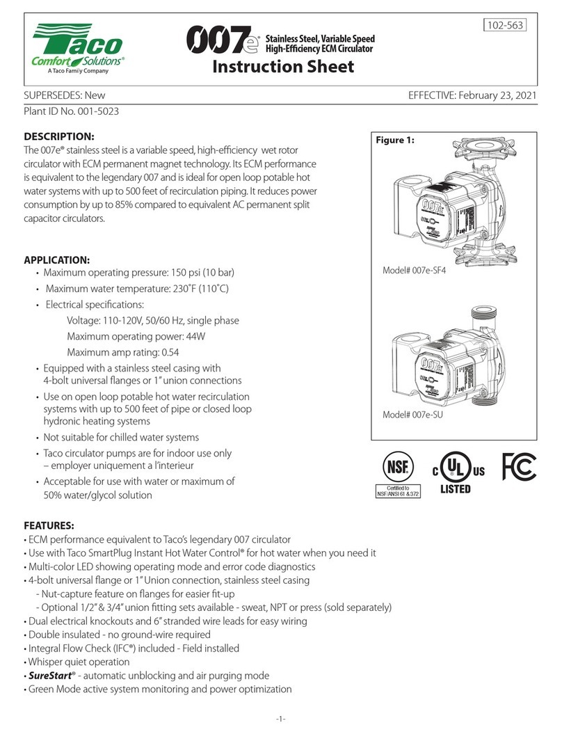
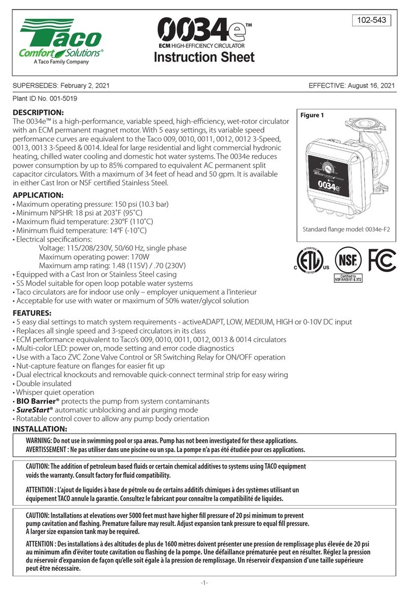
Taco Comfort Solutions 1900e Series User manual

SUPERSEDES: NEW Effective: January 21, 2019
302-388
Plant ID No. 001-5016
Instruction Sheet
1915e ECM Circulator

2
Section 1 - Installation and Operation
1.
2.
3.
3.1
4.
5.
6.
7.
8.
9.
10.
11.
12.
12.1
12.2
13
13.1
14.
14.1
15.
16.
17.
General Use........................................................
Safety...................................................................
Pump Description.................................................
Features...............................................................
Use......................................................................
Pumped Fluids.....................................................
Pump Installation.................................................
Motor Rotation.....................................................
Control Panel UI Rotation....................................
Seal Replacement................................................
System Start-up...................................................
Electrical Connections.........................................
Setup and Operation............................................
Control (UI) Panel Layout....................................
Switching On/Off..................................................
Pump Functions...................................................
Mode Descriptions...............................................
Specications.......................................................
Application...........................................................
Electrical Ratings.................................................
Standards, Protection, Connections....................
Materials of Construction.....................................
3
3
3
3
3
4
4
4
5
5
5
5
6
6
6
6
6
7
7
7
7
7
Section 2 - Controller Operation
18.
19.
20.
21.
21.1
22.
22.1
Features...............................................................
Specications.......................................................
Controller Layout..................................................
Connection Considerations..................................
Connection Examples..........................................
Fault Finding........................................................
Error Codes..........................................................
7
7
8
8
8
10
10
Limited Warranty Statement 10

3
Section 1. Installation and Operation
Warning: Installation and use of this product requires
experience and knowledge of this or similar products.
Persons with reduced physical, mental or sensory
capabilities must not use this product, unless properly
instructed and supervised. Children must not be allowed to
play with this product.
Avertissement: l'installation et l'utilisation de ce produit exigent
une expérience et des connaissances de ce produit ou de produits
semblables. Une personne aux capacités physiques, mentales ou
sensorielles réduites ne doit pas utiliser ce produit, à moins d’être
correctement instruite et supervisée. On ne doit pas laisser les enfants
jouer avec ce produit.
Introduction
This manual is broken down into two sections and describes the installation,
operation and control module for 1900e series pumps. Section 1 describes
the installation and operation features. Section 2 describes the control mod-
ule and its functions.
1 - General Information Uses
The 1900e series circulating pumps are available in 2 versions. The cast
iron version is used for the transfer of liquid media within a closed-loop
hot-water heating or air-conditioning hydronic system. They are to be used
with a water or glycol/water mixture. The stainless steel version is used
in potable DHW systems or where NSF/ANSI 61-G & 372 compliance is
required.
Both the cast iron and stainless steel versions are designed as single or
parallel main/standby operation variable-speed pumps, where the speed is
regulated by an on-board electronic device.
2 - Safety
These instructions should be studied carefully before installing or operating
the pump. They are meant to help you with installation, use and mainte-
nance and to increase your safety. Installation should be performed with re-
gards to local or national standards. Only qualied personnel should main-
tain and service these products. Failure to comply with safety precautions
could cause personal injury or machinery damage.
Warning: Do not use in swimming pool or spa areas. Pump
has not been investigated for these applications.
AVERTISSEMENT: Ne pas utiliser dans une piscine ou un
spa. La pompe n’a pas été étudiée pour ces applications.
Warning: To avoid electrical shock, disconnect the power
supply to the circulator and the main electrical unit. Follow
all local electrical and plumbing codes.
AVERTISSEMENT: Pour éviter tout choc électrique,
débranchez l’alimentation électrique vers le circu-lateur et
l’unité électrique principale. Respectez tous les codes de
plomberie et électriques locaux.
Warning: Hot surfaces can cause burns. The motor can
also reach temperatures that could cause injury.
AVERTISSEMENT: Les surfaces chaudes peuvent provo-
quer des brûlures. Le moteur peut également atteindre des
températures qui peuvent entraîner des blessures.
Warning: The addition of petroleum based uids or certain
chemical additives to systems using TACO equipment voids
the warranty.
AVERTISSEMENT: L’ajout de liquides à base de pétrole ou
de certains additifs chimiques à des systèmes utilisant un
équipement TACO annule la garantie.
Warning: Use supply wires suitable for 90°C.
Warning: Misconnection or overload of electrical or signal
connections could cause pump to shut-down or cause per-
manent damage.
AVERTISSEMENT: Employer des ls d’alimentation ade-
qauts pour 90°C.
AVERTISSEMENT: Toute erreur de raccordement ou sur-
charge des connexions électriques ou de signali-sation
peut entraîner un arrêt de la pompe ou des dommages
permanents.
Warning: Do not operate pump without the electrical cover
securely attached.
AVERTISSEMENT: Ne pas actionner la pompe si le cou-
vercleélectrique n’est pas correctement xé.
Warning: Pump motor, electronics enclosure and conden-
sate drain openings should not be thermally insulated as
it could interfere with cooling and condensate drainage.
AVERTISSEMENT: Lemoteur depompe, l’enceinte électro-
nique et les ouvertures de drainage de condensat doivent
être thermiquement isolés car il peut y avoir interférence
avec l’évacuation de condensat et deliquide de refroidisse-
ment.
3 - Pump Description
The high efciency, electronically commutated, close coupled 1900e series
pumps consist of two main parts; the centrifugal pump and the electronic
control. The hydraulic section is sealed from the motor assembly by a me-
chanical seal. 1900e series pumps are powered by an electronically com-
mutated permanent magnet motor (ECM) which does not consume energy
to magnetize the rotor, providing superior energy efciency.
The ECM motor is run by an on-board frequency converter. The converter
estimates current ow and head from the motor load. With this information
the self-sensing ECM pump constantly calculates pump pressure and ow
and adapts motor speed to the appropriate ow.
3.1 - Features
• 10 easy to set modes to match system requirements.
º4 - Constant Pressure modes.
º3 - Constant Speed modes.
º1 - Proportional Pressure mode.
º1 - 0-10v mode.
º1 - 2-pump operation mode.
• ECM performance equivalent to the versatile 1900 & 1600 series
pumps.
• Fully rotational User Interface (UI) to accommodate any pump position.
• LED status display showing power on and error code diagnostics.
• Mechanically sealed for easy maintenance.
4 - Use
All 1900e series pumps equipped with a cast iron casing are intended for
circulation of solid-free uid in pressurized, hot and chilled hydronic sys-
tems. All 1900e series pumps equipped with a stainless steel casing are
intended for DHW and potable water applications and are NSF Commercial
Hot (180°F water) rated and suitable for sanitizing applications.

4
6 - Pump Installation
The 1900e series pump is protected with a double box during shipping. It
can be lifted from the box by the heat sink.
Warning: Pump may be heavy. Provide yourself help if
needed.
Warning: The majority of mechanical seal failures are due
to poor media (uid) quality in the system. To maximize
seal life, media quality must be maintained in the system,
and TDS (Total Dissoled Solids)/TSS (Total Suspended
Solids) should not exceed 500ppm with standard carbon/
Silicon-Carbide seals. The use of inhibitor based glycols is acceptable,
but additional inhibitors should not be added. Always follow the glycol
manufacturer's specication for system preparation and water quality.
Treatment with silicates should not be used. Failure to maintain media
quality will void the standard Taco warranty.
AVERTISSEMENT: La plupart des défaillances des garnitures mé-
caniques sont dues à une mauvaise qualité de caloporteur. Pour pro-
longer la durée des joints, on doit maintenir la qualité du uide dans le
système et les solides dissouts totaux (SDT)/matières en suspension to-
tales (MES) ne doivent pas dépasser 500 ppm avec des joints standard
en carbone/carbure de silicium. L'utilisation de glycols/inhibiteurs com-
binés est acceptable, mais on ne doit y ajouter aucun inhibiteur supplé-
mentaire. Suivez toujours les spécications du fabricant du glycol pour la
préparation du système et la qualité du uide. On ne doit pas utiliser de
traitement aux silicates. Ne pas maintenir la qualité du uide annulera la
garantie standard de Taco.
AVERTISSEMENT: La pompe est lourde. Veillez à de-
mander de l’aide si nécessaire.
It is recommended that the1900e series pumps be installed with at least 5 to
10 pipe diameters of straight pipe on the inlet and outlet of the pump. Use all
nuts and bolts to attach companion anges to the pump anges.
The 1900e series model pumps can be installed with the motor shaft in the
horizontal position or the vertical position with the control module facing up
(see Figure 1). The cover can be rotated independent of the pump to adjust
orientation of the User Interface – the cable glands should never be pointed
upward to mitigate water ingress. The desired conduit box orientation can
be achieved by rotating the motor housing on the pump casing.
Caution: When reassembling, care should be taken to avoid damaging the
o-ring and insuring a good seal.
Figure 1.
Preferred Installation
Positions
Acceptable Installation
Positions
UNAUTHORIZED
Installation Positions
Attention! Installing pumps in UNAUTHORIZED positions may result in voiding the warranty.
Flange Bolt
Size FLANGE DIMENSIONS
Model (Flange
Size)
Bolt Hole
Diameter
Flange
Thickness
Minimum Bolt
Size Qty.
1915e (1 1/2”) 0.672 0.688 5/8” x 2 1/4” 2
PERMITTED AMBIENT AND MEDIA TEMPERATURE
Ambient
Temperature [°F]
Fluid Temperature
Min. [°F] Max. [°F]
Up to 75 36 230
85 36 212
95 36 203
105 36 175
Ambient
Temperature [°C]
Fluid Temperature
Min. [°C] Max. [°C]
Up to 25 2 110
30 2 100
35 2 90
40 2 80
Attention! Operation outside recommended conditions may shorten pump
lifetime and void the warranty.
7 - Motor Rotation Procedure
Caution: If system is lled and pressurized, shut off valve before and after
the 1900e series pump. Allow to cool if system uid is hot.
Notice! It is recommended to always change the orientation of the motor
before installing pump in piping.
5 - Pumped Fluids
In hot and chilled hydronic systems, use water or water/glycol mixtures only.
Water/glycol mixtures must be HVAC-system compatible and should have
no more than 50% concentration of glycol. The uid shall not consist of
aggressive or explosive additives, mixtures of mineral oils or solid or brous
particles. The pump should not be used for pumping ammable, explosive
uids, or in an explosive environment.
Desired pump orientation can be achieved by rotating the pump casing.
The pump is mounted to the volute with four screws. By removing those
the head can be turned. See detailed Motor Rotation Procedure 7 below.
Cast Iron Flange Kit 1600-031RP
Stainless Steel Flange Kit 198-3084RP

5
8 - Control Panel UI Rotation Procedure
a. Disconnect and lockout the electrical supply to the pump.
b. Remove the 4 screws securing the Control Panel UI to the Control Box.
c. Gently remove the Control Panel UI away from the Control Box.
Note: The control panel is connected to the High Voltage Power
Unit by a ribbon cable. The cable is long enough to accommodate
rotation without disconnecting the cable from the UI.
d. Rotate the Control Panel UI to the position desired.
e. Insert the screws and tighten in a crossing pattern.
9 - Seal Replacement
Mechanical Seal Options Seal Kit Number*
Standard Seal
Carbon/Silicon-Carbide/EPDM 198-3079RP
NSF Compatible Seal
Carbon/Silicon-Carbide/Viton 198-3080RP
Impeller Assembly, Standard Seal
Carbon/Silicon-Carbide/EPDM 198-3249RP
Impeller Assembly, NSF Compatible Seal
Carbon/Silicon-Carbide/Viton 198-3250RP
* Includes Gaskets (Casing, Flange and Drive Casing).
a. Disconnect and lockout the electrical supply to the pump.
b. Remove the conduit box cover and disconnect the electrical connec-
tions to the pump.
c. Relieve the system pressure, reduce the system temperature to ambi-
ent and drain the water from body.
d. Close isolation valves on suction and discharge sides of the pump. If
valves are not present, the system may need to be drained.
e. Remove ange nuts/bolts and the pump from the piping.
f. Loosen and remove the four body bolts that attach the motor assembly
to the pump body. Carefully remove the motor and control assembly
from the pump body.
g. Remove the User Interface (UI) cover from the motor/heat sink assem-
bly exposing the slotted pump shaft access port through the center of
the High Voltage Power Module.
h. Disconnect the ribbon cable from the UI panel.
i. Place the motor assembly in a horizontal position with the impeller and
slotted shaft end easily accessible.
j. The impeller is fastened to the shaft using a REVERSE (Left-Handed)
thread. To remove the impeller, carefully place the at end of a screw-
driver into the slotted shaft end. While holding the rotor/shaft in place
with the screwdriver, turn the impeller clockwise using your free hand to
remove the impeller from the shaft and gain access to the mechanical
seal.
NOTE: The impeller is made from a polymeric material, use caution
not to crack or otherwise damage the impeller.
k. Remove the complete seal assembly from the shaft.
l. Remove the seal face plate by gently prying it away from the housing.
m. Remove the old seal seat and cup from the seal face plate.
n. Thoroughly clean the impeller shaft before installing the new seal.
o. Lubricate the new cup with soapy water and install new parts in the face
plate recess.
p. Replace the face plate to its original position. Carefully tap the face
plate evenly into the recess in the motor housing assembly.
q. For DHW applications, lubricate the impeller shaft with soapy water, for
all other applications use the lubricant supplied with the seal kit.
NOTE: Do NOT install the new seal on a dry impeller shaft or dam-
age to the seal may result.
NOTE: Do NOT use any other oil or grease.
r. Slide the new carbon seal and spring assembly onto the shaft until it
contacts the seal seat.
s. While holding the shaft in place as used in the impeller removal steps,
thread the impeller onto the shaft in a counter-clockwise direction until
it stops. Check to make sure the impeller/shaft assembly will rotate. If
the impeller does not spin freely, contact Taco Technical Support at 1
(401) 942-8000.
t. Reconnect the ribbon cable from the High Voltage Power Module to the
UI panel.
u. Clean the gasket surfaces between the pump casing and Impeller/Motor
assembly. Using the new gasket provided with the seal kit, reassemble
the Impeller/Motor assembly to the casing and secure with the four body
bolts. Use caution not to pinch the body gasket or leaks may result.
Tighten the four bolts evenly in a crisscross pattern to 70 in-lb. of torque.
v. Reinstall the pump into the system using the new ange gaskets sup-
plied with the seal kit if required. Be sure that the arrow on the casing is
pointing in the right direction of ow.
w. Reconnect the electrical wiring. Do not turn on the electrical supply to
the pump until all “Start-Up” steps are complete.
x. Follow procedure outlined under START-UP section.
Caution: Do NOT remove the High Voltage Power Mod-
ule. Removal of the High Voltage Power Unit will void the
manufacturer’s warranty and may pose the Risk of Elec-
tric Shock.
10 - System Start-Up
a. The pump must always be lled with system uid and the system vented
as the pump uses a mechanical seal which requires uid lubrication.
b. Partially unscrew the highest point 1/8” NPT drain plug in the pump cas-
ing until only water trickles from the screw threads. Retighten the drain
plug as needed to seal the system.
c. The motor stator openings and stator housing should not be insulated.
The thermal insulation may prevent motor cooling and prohibit conden-
sate from escaping from the motor housing when used in high humidity
environments where the uid temperature is below the motor tempera-
ture.
d. Prior to pump start-up, closed heating and cooling systems should be
thoroughly cleaned and drained.
e. Open isolation valves and rell system with clean water. Check for any
leaks.
f. Vent all air from system at an air vent located at a high point in the sys-
tem and at the highest point 1/8" NPT casing drain plug.
g. Start the pump and check for proper operation.
NOTE: Pump casing includes three 1/8” NPT drain plugs to evacuate air
from the mechanical seal chamber prior to operation.
11 - Electrical Connections
a. Connection of the pump must comply with local electrical codes and
be carried out by qualied personnel. When connecting the pump, the
following must be considered:
b. Local or national electrical code requirements supersede Taco’s spec-
ication.
c. Install an electrical disconnect to comply with national electrical code.
d. Connection of the power supply electrical cable must be done in a man-
ner that ensures it does not contact the motor housing and volute of the
device, due to potential high temperatures of both.
e. The pump has built-in over current fuse protection, temperature pro-
tection, and basic overvoltage protection. It does not require additional
overload protection devices unless required by local electrical codes.
Power supply cabling should be capable of carrying rated power and be
properly fused. Grounding connection is essential for safety and should
be connected rst. System piping should be grounded separately.
f. Connect the black wire of the pump to the “Hot/ Live” wire of the system.
Typically black, or red wire if no black wire is present. When no black
Tools Required:
• 3/16” ball-end hex wrench
• ¼” or 3/8” at tip screw driver
a. With the motor in a vertical position, use the 3/16” ball-end hex wrench
to loosen and remove the 4 body bolts.
b. Using a at tip screwdriver if necessary, gently pry the motor away from
the pump housing. The motor is now ready to be rotated.
c. Rotate the motor so that the conduit box is in the desired position.
Note: The Control Panel UI is designed so that it can be rotated
separately. (see Section 8 Control Panel UI Rotation Procedure)
d. Reinstall the motor assembly to the pump housing being sure not to
damage the seal and the impeller is inserted into the wear ring of the
casing.
e. Insert the bolts and tighten in a crossing pattern.
6
12 - Setup and Operation
12.1 - Control (UI) Panel Layout
1
2
3
4
5
6
7
8
1. Status LED
2. Constant Pressure Mode Setting LED
3. Constant Speed Mode Setting LED
4. Proportional Pressure Mode LED
5. 0-10v Mode LED
6. 2 Pump Operation LED
7. [^] Select Mode Button
8. [O] Set Mode Button
12.2 - Switching the Pump On and Off
When the pump is powered for the rst time, it operates with the factory
default setting in Constant Pressure mode equal to 45ft of head.
The pump requires dry contact to run and comes with a jumper across the
ENABLE INPUT (J4) contacts found on the Control Panel UI. The pump
will run when connected to a power source when the jumper is connected.
Turning the pump on/off remotely is accomplished by accessing the EN-
ABLE INPUT (J4) contacts on the UI control board located under the UI and
connecting the contacts to an external relay. Access is gained by removing
the 4 screws located in each of the UI panel’s four corners.
13 - Pump Functions
[^] Select Mode Button
Short press: Change Mode
• Scrolling through operational modes upwards. Current operation-
al mode LED blinking. To accept the new mode press the Set
Mode button.
Long Press – LOCKOUT
• Pressing and holding the [^] Select Mode Button for 10 seconds
activates or deactivates pump LOCKOUT. In LOCKOUT, the cur-
rently selected mode is active only. No changes can be made
while in LOCKOUT. LOCKOUT activation or deactivation is ac-
knowledged by all LED’s blinking on/off 5 times.
[O] Set Mode Button
Short press: Conrm Selection
• To conrm the mode currently selected. Selected operational
mode LED solid.
NOTE: Pump returns to previous operational mode if Set Mode
is not pressed.
[^] Select Mode Button + [O] Set Mode Button
Long press (3 seconds): 2 Pump Operation
• To select or deselect 2 pump (lead/lag) operation.
13.1 - Pump Modes, 0-10Vdc and Parallel Pump Operation
The pump can operate in 9 different modes. Set the pump in the most ap-
propriate mode depending on the system where the pump operates.
The pump modes are:
Constant Pressure: 4 settings - 65ft, 45ft, 35ft, 25ft (Changes impeller
speed to maintain pressure as ow increases)
• The pump maintains the selected pressure from 0 ow to maximum
power. At maximum power the pressure begins to drop.
Constant Speed: 3 settings - 35ft, 25ft, 15ft (Maintains speed at selected
head at 0 ow)
• In Constant Speed mode the impeller speed is maintained through the
entire range of ow.
Automatic Mode: 1 setting (Proportional Pressure - increases impeller
speed to increase differential head as ow increases)
• In automatic mode the pump sets the operating pressure depending on
the system resistance.
• The parameters are preset and cannot be changed.
0 – 10Vdc:
• In this mode, all automatic curves are deactivated for full control via an
external signal. A dry contact from the external source is used to acti-
vate or deactivate the pump. Pump speed is controlled via a 0-10V DC
signal. Loss of the 0-10V DC signal defaults pump to 50% of full speed.
There is a 0-10V DC feedback signal to the BAS.
To switch between modes (except 2-Pump Operation) depress the [^] Se-
lect Mode button for 1 second. The selected mode LED will begin blinking.
Continue pressing the [^] Select Mode button to scroll through the avail-
able modes indicated by the mode’s blinking LED. Press the [O] Set Mode
button to accept the desired operating mode.
2-Pump Operation: 1 setting
• This option is selected when 2 pump alternation is desired.
• Pumps will alternate run-time every 24 hours (not adjustable).
• In this mode the lead pump will control the operation of the lag pump.
1. Set both pumps to the same Mode
2. Turn main power off to both pumps
3. Connect Primary Pump “P1” relay output common and NO to
“P2” Enable Input (see 21.1 - Connection Examples Parallel
Pump Operation). NOTE: Remove factory installed jumper
from “P2” Enable Input
4. Connect “P2” 0 – 10Vdc Output to “P1” 0-10Vdc Input, positive
to positive and negative to negative
5. NOTE: Between pump standard 18ga unshielded
communication wire is sufcient
To activate or deactivate 2-Pump Operation, press the [^] Select Mode
button + [O] Set Mode button together and hold for 3 seconds. The 2-Pump
Operation LED will light indicating 2-Pump Operation activation. The LED
will go out upon deactivation.
wire is present, a red wire is a sec-
ondary live wire found in some 220/1
circuits. Connect the white wire of
the pump to the white or gray neutral
wire of the system. The installation
green ground wire is connected to the
grounding terminal inside the pump
electrical box. See g 2 noted to the
left.
Figure 2
Electrical opening: ½” 14 MPSM standard thread

7
14 - Specication
14.1 - Application
• Maximum Operating Pressure: 175 PSI (12 bar)
• Water Temperature Range: 36°– 230°F (2.2°– 110°C)
• Ambient Operation Temperature Range: 32°– 104°F (0°– 40°C)
• Relative Humidity: Max. 95%
• Central heating application is designed for closed loop heating and cool-
ing systems pumping water or a water/glycol mixture.
• DHW application is designed for open loop potable water systems.
Rated NSF/ANSI 61-G & 372 Commercial Hot (180 °F)
• NPSHr - Minimum static inlet pressure at pump suction to avoid cavita-
tion and mechanical seal damage:
Fluid Temperatures PSI / bar
112°F (50°C) 7.3 / 0.5
176°F (80°C) 11.6 / 0.8
230°F (110°C) 20.3 / 1.4
14.2 - For indoor use only - employer uniquement a l’interieur.
15 - Electrical Ratings
Pump Ratings 1 phase, 200-240V, 47-63Hz
Power Consumption (HP) 0.027-0.75 HP
Power Consumption (W) 20-650W
Rated Current
(1 phase, 230V) 0.25-3.8A
Relay Output 30 VDC Max. Load up to 2A
24VAC Max. Load up to 3A
Analog Input Input Voltage: 0-10V, 10mA
Output Voltage: 0-10V, 10mA
16 - Standards, Protection and Connection
• Insulation: Class H (180 °C)
• Enclosure: Type 2
• Integrated Motor Protection (electronically protected)
• Continuous Duty
• UL778, 1004-1, 508C
• CAN/CSAC22.2#108, #100, #107.1, EMC (89/366EEC):EN61000
• Flange Connections: 2-bolt
17 - Materials of Construction
• Casing
• Impeller
• Shaft
• Bearing
Section 2. Controller Operation
18 - Features
This section describes the controller features for 1900e series of pumps.
The controller is used for various remote control applications, including:
• Remote on/off
• Analog 0 - 10 V voltage control
• Status relay feedback
There are several possible connection congurations. Not all functions can
be used simultaneously.
• on/off + 0 - 10 V + relay output
19 - Specications
Tables to the right provide an overview of Controller specications. For de-
tails, please refer to appropriate sections of this manual.
General Data
Ambient Humidity < 95% relative,
non-condensing
Also see appropriate pump
data for other ambient spec-
ications.
Analog Signals
Input Voltage Range 0 to 10V dc When used as input. 10 mA
max. drive required.
Output Voltage Range 0 to 10V dc When used as output. 10
mA max. load allowed.
Input Resistance ~3 kΩ
Relay Specications
Connection Type Terminal Block
Rating 24V AC, 3A
30V DC, 2A
HVAC application: Ductile Iron, Cataphoresis Coated
DHW application: Stainless Steel
PPS
Stainless Steel
Sealed for Life Ball Bearings, 6002 Series

8
20 - Controller Layout
Terminal Designation Description
RELAY OUTPUT Used to enable alarm output, Relay is closed during normal operation and open during alarm.
Used to enable slave pump when in 2 pump operation. The primary pump relay is used to turn on/off the slave pump
through the slave enable input.
ENABLE INPUT Jumper must be connected for pump to run. (DEFAULT CONFIGURATION)
Use with external dry contact relay for remote on/off
0 - 10V DC Input Used to receive speed control from an external control.
Used to receive input from Slave pump when in 2 pump operation to verify operation.
0 - 10V DC Output Used to send signal to Master in 2 pump operation
Used to control the speed of the pump from external controller
MOTOR CONTROLLER
RIBBON CABLE
Connects High Voltage Power Module to UI. If the cable becomes disconnected, reconnect to “MOTOR CONTROL
RIBBON CABLE” connector.
21 - Connection Considerations
• All cables connected must be heat-resistant to at least +185 °F.
• All cables connected must be installed in accordance with The National
Electric Code NFPA 79 / EN 60204-1.
• All wires to the communications module must be connected to the termi-
nals or cut. No loose wiring permitted.
Warning: Voltages over 24V AC/DC are possible on NO,
C, NC Terminals.
Cable outer layer must not be stripped longer than 0.59
inches.
Warning: Before performing any work on the module, make
sure that the pump and module electricity supply has been
switched off and that it cannot be accidently switched on.
21.1 - Connection Examples
DEFAULT (FACTORY) Conguration
REMOTE START - Analog Control 1
REMOTE START - Analog Control 2

9
REMOTE START - Analog Control 3 2-PUMP OPERATION - Lead Pump
2-PUMP OPERATION - Lag Pump
Analog Control Curve
RUN Voltage MAX Voltage Function
> 1 V < 3 V Pump at minimum speed.
= 0 V < 2 V Pump is at 1/2 speed.
> 3 V 3 to 10 V Speed is proportional to voltage regulation.

22 - Fault Finding
The pump’s LEDs will ash RED to display Error Codes to help you diagnose a fault condition.
The following LED ashing sequences will show up on UI.
Error Code (blinks in
1/2 second intervals) Description Probable Cause(s)
1 blink Locked Rotor Impeller is unable to turn - debris in system
2 blinks Over Current High Motor Load
3 blinks Over Temperature Motor might be faulty or viscous medium is present.
High Motor Load, Water Temperature too hot, Pump running dry.
4 blinks Over Voltage Line voltage is too high.
5 blinks Under Voltage Line voltage is too low for proper operation.
6 blinks Communication Fault
7 blinks Motor Temperature Fault Control temperature near maximum limit.
Control reduces rpm to reduce heat.
8 blinks Staging Fault
22.1 - Error Codes
LIMITED WARRANTY STATEMENT
Taco, Inc. will repair or replace without charge (at the company’s option) any
commercial pump product or part which is proven defective under normal
use within one (1) year from the date code.
Seals provided on commercial pumps are not covered by this warranty.
In order to obtain service under this warranty, it is the responsibility of the
purchaser to promptly notify the local Taco stocking distributor or Taco in
writing and promptly deliver the subject product or part, delivery prepaid, to
the stocking distributor. For assistance on warranty returns, the purchaser
may either contact the local Taco stocking distributor or Taco. If the subject
product or part contains no defect as covered in this warranty, the purchaser
will be billed for parts and labor charges in effect at time of factory
examination and repair.
Any Taco product or part not installed or operated in conformity with Taco
instructions or which has been subject to misuse, misapplication, the
addition of petroleum-based uids or certain chemical additives to the sys-
tems, or other abuse, will not be covered by this warranty.
If in doubt as to whether a particular substance is suitable for use with a
Taco product or part, or for any application restrictions, consult the
applicable Taco instruction sheets or contact Taco at [401-942-8000].
Taco reserves the right to provide replacement products and parts which
are substantially similar in design and functionally equivalent to the
defective product or part. Taco reserves the right to make changes in details
of design, construction, or arrangement of materials of its products without
notication.
TACO OFFERS THIS WARRANTY IN LIEU OF ALL OTHER EXPRESS
WARRANTIES. ANY WARRANTY IMPLIED BY LAW INCLUDING
WARRANTIES OF MERCHANTABILITY OR FITNESS IS IN EFFECT
ONLY FOR THE DURATION OF THE EXPRESS WARRANTY SET
FORTH IN THE FIRST PARAGRAPH ABOVE.
THE ABOVE WARRANTIES ARE IN LIEU OF ALL OTHER WARRAN-
TIES, EXPRESS OR STATUTORY, OR ANY OTHER WARRANTY OBLI-
GATION ON THE PART OF TACO.
TACO WILL NOT BE LIABLE FOR ANY SPECIAL, INCIDENTAL, INDI-
RECT OR CONSEQUENTIAL DAMAGES RESULTING FROM THE USE
OF ITS PRODUCTS OR ANY INCIDENTAL COSTS OF REMOVING OR
REPLACING DEFECTIVE PRODUCTS.
This warranty gives the purchaser specic rights, and the purchaser may
have other rights which vary from state to state. Some states do not allow
limitations on how long an implied warranty lasts or on the exclusion of in-
cidental or consequential damages, so these limitations or exclusions may
not apply to you.
A Taco Family Company
2019
This manual suits for next models
3
Table of contents
Other Taco Comfort Solutions Water System manuals

Taco Comfort Solutions
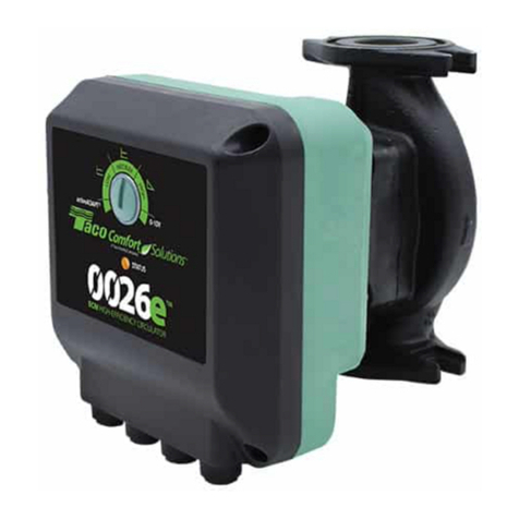
Taco Comfort Solutions 0026e User manual

Taco Comfort Solutions
Taco Comfort Solutions 0018e-SF4 User manual

Taco Comfort Solutions
Taco Comfort Solutions 0034e User manual

Taco Comfort Solutions
Taco Comfort Solutions Plumb n' Plug 00 Series User manual

Taco Comfort Solutions
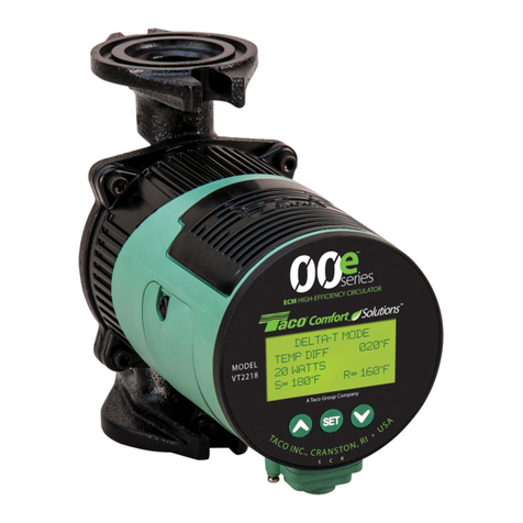
Taco Comfort Solutions 00e VT2218 Series User manual

Taco Comfort Solutions
Taco Comfort Solutions 0015-MSF-IFC User manual

Taco Comfort Solutions
Taco Comfort Solutions 2400 Series User manual

Taco Comfort Solutions
Taco Comfort Solutions 007e Series User manual

Taco Comfort Solutions
Taco Comfort Solutions 007e-2 User manual