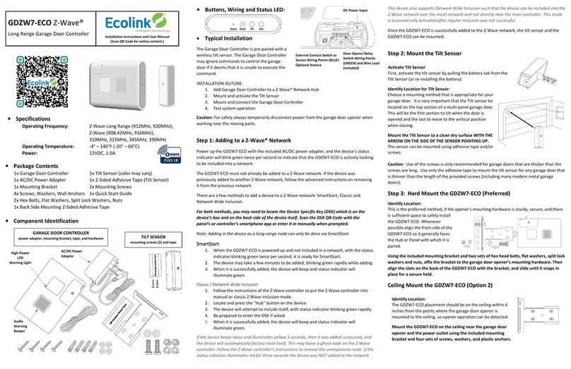
Ecolink GDZW7-ECO User manual

1 | P a g e
Z-Wave™ Long Range
Garage Door Controller
User Manual
M/K: GDZW7-ECO
Revision 2
Product Overview
The Garage Door Controller is a security device for users to wirelessly control and monitor their garage door.
It monitors and reports the state of the garage door through use of a paired wireless (or wired) tilt sensor. It
can also determine when the garage door is active by utilizing an accelerometer to detect specific vibration
patterns. The Garage Door Controller may ignore commands to control the garage door if it deems that is
unsafe to execute the command.
Product Specification
•Supports Z-Wave™ Long Range (must be added via SmartStart)
•Indoor use only
•Operating Frequency: 345MHz, Z-Wave (908.42MHz, 916MHz), Z-Wave Long Range (912MHz,
920MHz)
•Operating Temperature: 0°F to 120°F
•Power: 12VDC, 1.0A
•Accelerometer 2-16G I2C/SPI
•External contact for installer to opt in using magnetic contact instead of using tilt sensor for
determination of the garage door’s state
•Temperature sensor
•S2 Encryption

2 | P a g e
Definitions
•Panel or Controller are used interchangeably here and is what you are pairing the device with.
•Device Specific Key (DSK) –PIN Code and QR-Code Used for inclusion and to setup encrypted S2
communication.
•S2 –Secure Communication Technology.
•SmartStart –New method for easy inclusion.
•Inclusion / Adding / Pairing –Adding to a device to a Z-Wave network.
•Exclusion / Removal / Unpairing –Removing a device from a Z-Wave network or at least unpairing a
device from a network that it had been added to previously.
•Node Info Frame –Used for inclusion/Exclusion carrying information about the device.
Adding to or Removing from a Z-Wave Network
Adding:
Power up the Garage Door Controller, and the device’s status indicator will blink green three times every six
seconds to indicate that the Garage Door Controller is actively looking to be included into a network. The
Garage Door Controller must not already be added to a Z-Wave network. If the device is added to a Z-Wave
network, follow instructions below on removing. There are a few methods to add a device to a Z-Wave
network: SmartStart, Classic and Network Wide Inclusion.
For both methods, you may need to locate the Device Specific Key (DSK) which is on the device’s box and on
the back side of the device itself. Scan the DSK QR-Code with the panel’s or controller’s smartphone app or
enter it in manually when prompted.
***Note: Adding in the device as a long range node can only be done via SmartStart.
SmartStart:
1. When the Garage Door Controller is powered up and not included in a network, it is ready for
SmartStart. The status indicator will blink green three times every six seconds.
2. The device may take a few minutes to be added.
3. When it is successfully added, the device will beep and blink green once.
Classic / Network-Wide Inclusion
1. Follow the instructions of the Z-Wave controller to put the Z-Wave controller into manual or classic
Z-Wave inclusion mode.
2. Locate and press the hub button on the device.
3. The device will attempt to include itself.
4. Be prepared to enter the DSK if asked.
5. When it is successfully added, the device will beep and blink green once.
If the device beeps twice and blinks yellow once, then it was added unsecured, and the device will
automatically factory reset itself. This may leave a ghost node on the Z-Wave controller. Follow the Z-Wave
controller’s instructions to remove the unresponsive node.
This device also supports Network Wide Inclusion such that the device can be included into the Z-Wave
network over the mesh network and not directly near the main controller. This mode is automatically
activated after regular inclusion was not successful.

3 | P a g e
Removal:
There are two methods to removing the Garage Door Controller from a Z-Wave network: exclusion and
performing a factory reset (see section on Factory Reset).
1. Follow the Z-Wave controller’s instructions on putting the Z-Wave controller into removal/exclusion
mode.
2. Locate and press the hub button.
3. Device’s status indicator will blink red and beep three times to indicate successful removal.
Mounting and Connections to Garage Door Opener
Mount the tilt sensor to the top panel of the garage door. Mount the Garage Door Controller to the garage
door opener’s hardware using the included mounting bracket. Alternatively, you can mount the Garage Door
Controller on the ceiling near the garage door opener and the power outlet. Connect the Garage Door
Controller’s relay switch wires to the pushbutton wall console terminals on the garage door opener. Make
sure not to disconnect any wires that are already connected to the garage door opener.
Factory Reset
Please use this procedure only when the network primary controller is missing or otherwise inoperable.
Factory resetting the Garage Door Controller will default it to factory settings and reset the tilt sensor pairing
to the original tilt sensor.
1. Locate the reset button.
2. Insert a paperclip into the hole until you feel the button depress. There will be a short beep.
3. Hold the button down for ten seconds. The status indicator will blink red while the reset button is
pressed and will go out after ten seconds.
4. The device’s status indicator will turn green when the reset operation is complete. The device is now
ready to be added to a Z-Wave network.
Note: Factory reset only works when the device is already added into a Z-Wave network. If the Garage Door
Controller is not included in a network, then it cannot be factory reset.
Adding a Tilt Sensor
The Garage Door Controller pairs with the tilt sensor to monitor the state of the garage door.
The original (included with the Garage Door Controller) tilt sensor does not need to be added. To add a
different Ecolink ClearSky tilt sensor:
1. Locate and press the tilt button. There will be a short beep.
2. Remove pull-tab from the tilt sensor or reinsert the battery into the tilt sensor.
3. If pairing is successful, the device’s warning light will blink white and beep for one second.

4 | P a g e
Adding an External Contact
Alternatively, the Garage Door Controller can pair with an external contact to monitor the state of the garage
door.
To add a hardwired external contact:
1. Connect the external contact’s wires to the Garage Door Controller’s blue terminal block
2. Locate and press the tilt button. There will be a short beep.
3. Trigger the external contact to the “open” state.
4. If pairing is successful, the device’s warning light will blink white and beep for one second.
What is Z-Wave?
The Z-Wave protocol is an interoperable, wireless, RF-based communications technology designed
specifically for control, monitoring and status reading applications in residential and light commercial
environments. Mature, proven and broadly deployed (with over 35 million products sold worldwide), Z-Wave
is by far the world market leader in wireless control, bringing affordable, reliable and easy-to-use 'smart'
products to many millions of people in every aspect of daily life. Certified Z-Wave devices regardless of
manufacturer can work together to form a Z-Wave mesh network. Always on Z-Wave devices can act as
repeaters in the mesh increasing range and redundancy.
For a more complete look at Z-Wave technology for non-technologists, and to learn more about Z-Wave's
role as a key enabling technology for the Internet of Things and connected objects, please visit z-wave.com.
What is Z-Wave Long Range?
Engineered to provide significantly extended wireless range and support robust networks, Z-Wave LR extends
Z-Wave connectivity beyond the boundaries of the home and accelerates the adoption of Z-Wave in other
verticals such as light commercial, hospitality, and multi-dwelling units (MDU). Z-Wave Long Range is an extra
100kbps DSSS OQPSK modulation addition to the Z-Wave protocol. The modulation is treated as a fourth
channel –allowing gateways to add LR nodes to the existing Z-Wave channel scanning. At this time, Z-Wave
LR is only available for the US market however, the Technical Workgroup is evaluating and testing to ensure
compliance and to be able to support Europe and APAC regions in the future.
Z-Wave Device Class and Command Class Information
This device is a Z-Wave generic Device Class of GENERIC_TYPE_ENTRY_CONTROL (0x40), and a specific device
class of SPECIFIC_TYPE_SECURE_GATE (0x06).
Manufacturer Specific
•Manufacturer ID: 0x014A
•Product Type: 0x0007
•Product ID: 0x4731

5 | P a g e
Mapping of the Basic Command Class
The Garage Door Controller has the Basic Command Class mapped to the Barrier Operator Command Class
such that a Basic Set of a value is the equivalent of a Barrier Operator Set of a target value. A Barrier Operator
Report with a state of 0x00 will map to a Basic Report with a current value of 0x00. And a Barrier Operator
Report with a state > 0x00 will map to a Basic Report with a current value of 0xFF.
Z-Wave Command Classes
Command Class
Version
Secured via S2
Z-Wave Plus Info
2
Association
2
√
Association Group Info
3
√
Barrier Operator
1
√
Configuration
4
√
Device Reset Locally
1
√
Firmware Update Metadata
5
√
Indicator
3
√
Manufacturer Specific
2
√
Multichannel Association
3
√
Multilevel Sensor
11
√
Notification
8
√
Power Level
1
√
Security 2
1
Security 0
1
Supervision
1
Transport Service
2
Version
3
√
Association
The Garage Door Controller supports one Association group: the “Lifeline” group which can have one node in
the group. All unsolicited Z-Wave messages are transmitted to the node in the Lifeline group such as Barrier
Operator, Device Reset Locally notifications, Indicator, and Notification.
Barrier Operator
The Garage Door Controller supports the Barrier Operator Command Class which is used to control and query
the status of the garage door. A Barrier Operator Set Command of 0xFF will initiate an unattended open, and
a command of 0x00 will initiate an unattended close. Before an unattended close command is executed, it
will have a minimum wait period of 5 seconds, during which the warning light will flash, and the speaker will
beep. If the state of the garage door changes or the garage door is active during this unattended wait period,
the original close command will be ignored.

6 | P a g e
Any state/command pair not specified in the following figure will not cause any action:
The Garage Door Controller will not respond to Set Commands if any of the following issues are detected:
- No tilt sensor is paired
- Tilt sensor is tampered
- Tilt sensor counter is out of sync
-Tilt sensor is lost (Garage Door Controller hasn’t heard from the tilt sensor in 2 hours)
- Tilt sensor is in the wrong state
A timeout error will occur if the tilt sensor does not change states after an unattended open/close command
is executed. After a timeout error occurs, Barrier Operator Set open/close commands will be ignored until
the garage door operator is manually triggered by the user and the tilt sensor changes states.
Whenever the Garage Door Controller receives and ignores a Barrier Operator Set Command, the Garage
Door Controller’s warning light will blink 3 times.
The “Stopped” state is removed because the tilt sensor only reports open or closed: there is no way to
confidently know that the garage door is stopped.
Barrier Operator Signal Set Commands can be sent but will not cause any action to the audible or visual
subsystems.
Configuration
The Garage Door Controller supports the six configuration parameters listed below.
1. Unattended Wait Period
Description
Unattended close operation wait period in seconds.
Size
1
Format
Unsigned Integer

7 | P a g e
Read only
No
Min Value
5
Max Value
60
Default Value
5
2. Relay Switch Period
Description
Number of milliseconds to turn on relay switch for.
Size
2
Format
Unsigned Integer
Read only
No
Min Value
100
Max Value
5000
Default Value
1000
3. Door Open Timeout
Description
Seconds allowed for garage door to open until timeout.
Size
1
Format
Unsigned Integer
Read only
No
Min Value
5
Max Value
60
Default Value
20
4. Door Close Timeout
Description
Seconds allowed for garage door to close until timeout.
Size
1
Format
Unsigned Integer
Read only
No
Min Value
5
Max Value
60
Default Value
15
5. Accelerometer Sensitivity
Description
Accelerometer vibration detection sensitivity: 1 is least sensitive, 100 is most
sensitive.
Size
1
Format
Unsigned Integer
Read only
No
Min Value
1
Max Value
100
Default Value
96

8 | P a g e
6. Application-Level Retries
Description
Number of attempts on top of the stack-level retries to try to reach the
controller/hub with Z-Wave messages.
Size
1
Format
Unsigned Integer
Read only
No
Min Value
0
Max Value
10
Default Value
3
Indicator
Indicator
ID
Name
Binary
Level
Time
Out
Seconds
On-Off
Period
One
Time
On-Off
Period
On-Off
Cycles
0x50
Identify
0x02
0x01
0x07
0x03
0x05
0x04
The indicators supporting properties On-Off Period, One Time On-Off Period, and On-Off Cycles can safely
interrupt the other indicators, and the other indicators if active will resume.
The Identify indicator flashes the device’s status indicator.
Multilevel Sensor
The temperature is reported through the Multilevel Sensor Command Class. The temperature sensor is polled
every 30 seconds and any change in temperature will send a Multilevel Sensor Report. A Multilevel Sensor
Report will also be sent if the temperature has not changed in the past hour. Temperature is reported in
Celsius with a precision of one (e.g. a decimal value of 212 would be equivalent to 21.2 °C).
Notification
The following Notifications are supported and sent to the Lifeline Association Group.
Type
Event
Access Control (0x06)
Window/door is open (0x16)
Window/door is closed (0x17)
Barrier motor has exceeded manufacturer’s operational time limit
(0x42)
Barrier unable to perform requested operation due to UL requirements
(0x44)
Barrier sensor not detected / supervisory error (0x49)
Barrier sensor low battery warning (0x4A)
System (0x09)
Tampering, product cover removed (0x06)
Supervision
When included with S2, all unsolicited Z-Wave messages from the device to the Z-Wave controller are
encapsulated in a Supervision Get command to ensure proper decoding, so the device must see both an ACK
and a corresponding Supervision Report to consider the message communicated successfully.

9 | P a g e
Indicator (LED and Beeper) States
Event
LED Behavior
Beeper Behavior
Beeper Tone
SmartStart
3 green blinks (500ms on/off), off
for 3 seconds
None
None
Classic Inclusion
3 green blinks (500ms on/off), off
for 3 seconds
None
None
Inclusion in progress
repeated green blinks (100ms
on/off)
None
None
Secured pairing
completed
3 seconds green
1 second beep
Good tone
(2240 Hz)
Unsecured pairing
completed
3 seconds yellow
2 quick beeps: 200ms
on, 100ms off
Bad tone
(1050 Hz)
Inclusion failed
3 seconds red
None
None
Learn timeout
3 alternating red and green blinks
(500ms on/off)
None
None
Exclusion
3 seconds red
3 quick beeps: 200ms
on, 100ms off
Bad tone
(1050 Hz)
Factory Default Wait
red blinks(250ms on/off) for 10
seconds
None
None
Factory Default Success
5 seconds green
None
None
Powered on when
included
5 seconds green
None
None
Any button press
None
200ms beep
Button press
(2790 Hz)
Tilt sensor or external
contact pairing
successful
1 second white
1 second beep
Good tone
(2240 Hz)
Barrier Set Command
was ignored due to a
tilt sensor error or
safety issue
3 white blinks (250ms on/off)
None
None
Unattended close wait
period
repeated white blinks(100ms on,
150ms off)
repeated beeps:
100ms on, 150ms off
Good tone
(2240 Hz)
OTA Firmware Update
100ms green/100ms red, every
10 seconds
None
None

10 | P a g e
Troubleshooting
Problem
Possible Cause
Solution
Unable to add device
to Z-Wave network
Device was not properly
excluded from a previous Z-
Wave network
Try removing the device by putting the Z-Wave
controller into exclusion mode and then
pressing the Garage Door Controller’s Hub
button.
You can also factory reset the device in the
case of a missing or inoperative Z-Wave
controller.
Z-Wave open/close
commands don’t do
anything and warning
lights flashes 3 times
One of the following:
- Tilt sensor is lost
- Tilt sensor is tampered
- Tilt sensor counter is out of
sync
- Previous close/open
operation timed out
To determine the cause, check the Notification
Report which is sent in response to an ignored
Z-Wave open/close command.
If the tilt sensor is tampered, make sure the
sensor covering is properly closed.
For all other causes, manually operate the
garage door opener via the pushbutton wall
console to resync the tilt sensor and Garage
Door Controller.
Device flashes and
beeps during the
unattended wait
period, but the door
does not move
Device detected a vibration
during the unattended wait
period and cancelled the
original close command.
Send the close command again. If this is a
recurring issue, consider lowering the
accelerometer sensitivity (Configuration
Parameter #5)
Device’s relay switch is
activated, but the door
does not move
Incorrect wiring
Make sure the relay switch wires are
connected to the correct terminals on the
garage door opener terminal. They should be
connected to the garage door opener’s
pushbutton wall console terminals. Do not
disconnect any wires from the garage door
opener.

11 | P a g e
FCC Compliance Statement
FCC ID: XQC-GDZW7
IC ID: 9863B-GDZW7
This device complies with part 15 of the FCC Rules. Operation is subject to the following two conditions:
(1)
This device may not cause harmful interference, and
(2)
this device must accept any interference received, including interference that may cause undesired operation.
This equipment has been tested and found to comply with the limits for Class B digital devices, pursuant to Part 15 of the FCC Rules. These limits are
designed to provide reasonable protection against harmful interference in a residential installation. This equipment generates uses and can radiate radio
frequency energy and, if not installed and used in accordance with the instruction manual, may cause harmful interference to radio communications.
However, there is no guarantee that interference will not occur in a particular installation. If this equipment does cause harmful interference to radio or
television reception, which can be determined by turning the equipment off and on, the user is encouraged to try to correct the interference by one or more
of the following measures:
•
Re-orient or relocate the receiving antenna
•
Increase the separation between the equipment and receiver
•
Connect the equipment to an outlet on a different circuit from the receiver
•
Consult the dealer or an experienced radio/TV contractor for help.
Warning: Changes or modifications not expressly approved by Ecolink Intelligent Technology Inc. could void the user’s authority to operate the
equipment.
IC Compliance Statement
This device complies with Industry Canada licence-exempt RSS standard(s). Operation is subject to the following two conditions:
(1)
this device may not cause interference, and
(2)
this device must accept any interference, including interference that may cause undesired operation of the device.C’et appareil est conforme la norme
d'Industrie Canada exempts de licence RSS. Son fonctionnement est soumis aux deux conditions suivantes: (1) c’et appareil ne peut pas provoquer
d'interférences, et (2) c’et appareil doit accepter toute interférence, y compris les interférences qui peuvent causer un mauvais fonctionnement de la
dispositif.
Warranty
Ecolink Intelligent Technology Inc. warrants that for a period of 1 year from the date of purchase that this product is free from defects in material and
workmanship. This warranty does not apply to damage caused by shipping or handling, or damage caused by accident, abuse, misuse, misapplication,
ordinary wear, improper maintenance, failure to follow instructions or as a result of any unauthorized modifications.
If there is a defect in materials and workmanship under normal use within the warranty period Ecolink Intelligent Technology Inc. shall, at its option, repair
or replace the defective equipment upon return of the equipment to the original point of purchase.
The foregoing warranty shall apply only to the original buyer, and is and shall be in lieu of any and all other warranties, whether expressed or implied and of
all other obligations or liabilities on the part of Ecolink Intelligent Technology Inc. neither assumes responsibility for, nor authorizes any other person
purporting to act on its behalf to modify or to change this warranty, nor to assume for it any other warranty or liability concerning this product.
The maximum liability for Ecolink Intelligent Technology Inc. under all circumstances for any warranty issue shall be limited to a replacement of the
defective product. It is recommended that the customer check their equipment on a regular basis for proper operation.
© 2021 Ecolink Intelligent Technology Inc.
Other manuals for GDZW7-ECO
1
Table of contents
Other Ecolink Controllers manuals