Emerson Fisher 3610J User manual

www.Fisher.com
Errata Sheet
for
3610J and 3620J Series Positioners,
D200149X012, June 2008
This errata sheet includes updated electromagnetic
compatibility (EMC) information for the 3622
electro-pneumatic converter.
DReplace the portion of the Typical
Performance for 3610J, 3610JP, 3620J, and
3620JP Positioners with 1051, 1052, and1061
Actuators section titled Electromagnetic
Interference (EMI),found in Table 1. Specifications,
with the following updated information:
Electromagnetic Compatibility for 3622
electro-pneumatic converter
Meets EN 61326-1 (First Edition)
Immunity—Industrial locations per Table 2 of the
EN 61326-1 standard. Performance is shown
in table 2 below.
Emissions—Class A
ISM equipment rating: Group 1, Class A
The electromagnetic compatibility
specifications also apply to 3620J, 3620JP,
and 3621JP electro-pneumatic positioners.
DReplace Table 2. EMC Immunity Performance
Criteria for 3620J, 3620JP, 3621JP and 3622 with
the updated table 2 below.
Note
Neither Emerson, Emerson Process
Management, nor any of their affiliated
entities assumes responsibility for the
selection, use, or maintenance of any
product. Responsibility for the
selection, use, and maintenance of any
product remains with the purchaser
and end-user.
Table 2. 3622 Electro-Pneumatic Converter(1) EMC Summary Results—Immunity
Port Phenomenon Basic Standard Test Level Performance
Criteria(1)
Enclosure
Electrostatic Discharge (ESD) IEC 61000-4-2 4 kV contact; 8 kV air A
Radiated EM field IEC 61000-4-3
80 to 1000 MHz @ 10V/m with 1 kHz AM at 80%
1400 to 2000 MHz @ 3V/m with 1 kHz AM at 80%
2000 to 2700 MHz @ 1V/m with 1 kHz AM at 80%
A
Rated power frequency magnetic field IEC 61000-4-8 60 A/m at 50 Hz A
I/O signal/control
Burst IEC 61000-4-4 1 kV A
Surge IEC 61000-4-5 1 kV (line to ground only, each) B
Conducted RF IEC 61000-4-6 150 kHz to 80 MHz at 3 Vrms A
Specification limit = ±1% of span
1. The information contained in the table also applies to 3620J, 3620JP, and 3621JP electro-pneumatic positioners.
2. A=No degradation during testing. B = Temporary degradation during testing, but is self-recovering.
Errata Sheet
February 2009 3610J and 3620J Positioners

3610J and 3620J Positioners Errata Sheet
February 2009
2
Emerson Process Management
Marshalltown, Iowa 50158 USA
Sorocaba, 18087 Brazil
Chatham, Kent ME4 4QZ UK
Dubai, United Arab Emirates
Singapore 128461 Singapore
EFisher Controls International LLC 2009; All Rights Reserved
www.Fisher.com
The contents of this publication are presented for informational purposes only, and while every effort has been made to ensure their accuracy, they
are not to be construed as warranties or guarantees, express or implied, regarding the products or services described herein or their use or
applicability. All sales are governed by our terms and conditions, which are available upon request. We reserve the right to modify or improve the
designs or specifications of such products at any time without notice. Neither Emerson, Emerson Process Management, nor any of their affiliated
entities assumes responsibility for the selection, use or maintenance of any product. Responsibility for proper selection, use, and maintenance of
any product remains solely with the purchaser and end-user.
Fisher is a mark owned by one of the companies in the Emerson Process Management business division of Emerson Electric Co. Emerson
Process Management, Emerson, and the Emerson logo are trademarks and service marks of Emerson Electric Co. All other marks are the property
of their respective owners.

www.Fisher.com
3610J and 3620J Series Positioners
Contents
Introduction 2. . . . . . . . . . . . . . . . . . . . . . . . . . . . . . .
Scope of Manual 2. . . . . . . . . . . . . . . . . . . . . . . . .
Description 2. . . . . . . . . . . . . . . . . . . . . . . . . . . . . .
Type Number Description 5. . . . . . . . . . . . . . . . . .
Specifications 5. . . . . . . . . . . . . . . . . . . . . . . . . . . .
Educational Services 5. . . . . . . . . . . . . . . . . . . . . .
Installation 6. . . . . . . . . . . . . . . . . . . . . . . . . . . . . . . .
Special Instructions for “Safe Use” and
Installation in Hazardous Locations 6. . . . . . .
CSA 6. . . . . . . . . . . . . . . . . . . . . . . . . . . . . . . . . . .
FM 6. . . . . . . . . . . . . . . . . . . . . . . . . . . . . . . . . . . .
ATEX Intrinsic Safety 7. . . . . . . . . . . . . . . . . . . .
ATEX Type n 7. . . . . . . . . . . . . . . . . . . . . . . . . . .
ATEX Flameproof 8. . . . . . . . . . . . . . . . . . . . . . .
SAA Intrinsic Safety/Type n 8. . . . . . . . . . . . . . .
SAA Flameproof 8. . . . . . . . . . . . . . . . . . . . . . . . .
Mounting 3610J, 3610JP,
3620J, and 3620JP Positioners 9. . . . . . . . . .
Changing Cams—Actuator
Styles A, B, C, and D 10. . . . . . . . . . . . . . . . . .
Mounting 3611JP and 3621JP Positioners
on 585 and 585R Actuators 12. . . . . . . . . . . . .
Mounting 3611JP and 3621JP Positioners
on 585C and 585CR Actuators 12. . . . . . . . . .
Installing the 3622
Electro-Pneumatic Converter 14. . . . . . . . . . .
Changing Positioner Types 14. . . . . . . . . . . . . . .
Pressure Connections 14. . . . . . . . . . . . . . . . . . . .
Supply Connection 16. . . . . . . . . . . . . . . . . . . . .
Output Connections 17. . . . . . . . . . . . . . . . . . . . .
Instrument Connection 17. . . . . . . . . . . . . . . . . .
Diagnostic Connections 18. . . . . . . . . . . . . . . . .
Vent Connection 18. . . . . . . . . . . . . . . . . . . . . . . . .
Electrical Connections
for 3620J Series Positioners 19. . . . . . . . . . . .
Calibration 19. . . . . . . . . . . . . . . . . . . . . . . . . . . . . . .
Minor Loop Gain Adjustment 20. . . . . . . . . . . . . .
Crossover Adjustment 20. . . . . . . . . . . . . . . . . . . .
3610J or 3620J Positioner,
Spring and Diaphragm Actuators 20. . . . . . .
3610JP, 3611JP, 3620JP, or 3621JP
Positioner, Piston Actuators 21. . . . . . . . . . .
Zero and Span Adjustments 22. . . . . . . . . . . . . . .
(continued on page 2)
3610J POSITIONER AND BYPASS VALVE WITH
1052 ACTUATOR AND ECCENTRIC DISC ROTARY VALVE
3620JP POSITIONER WITH 1061
ACTUATOR AND V500 VALVE
W4920−1 / IL
W3949 / IL
Figure 1. Typical Positioners
Instruction Manual
D200149X012
June 2008 3610J and 3620J Positioners

3610J and 3620J Positioners
Instruction Manual
June 2008
2
Contents (continued)
Changing Positioner Action 23. . . . . . . . . . . . . . .
Changing to Direct Action 23. . . . . . . . . . . . . . . .
Changing to Reverse Action 24. . . . . . . . . . . . .
Split Range Operation 24. . . . . . . . . . . . . . . . . . . .
Characterized Cams for 3610J, 3610JP,
3620J, and 3620JP Positioners 25. . . . . . . . .
Principle of Operation 26. . . . . . . . . . . . . . . . . . . . .
Maintenance 28. . . . . . . . . . . . . . . . . . . . . . . . . . . . .
Positioner Disassembly 30. . . . . . . . . . . . . . . . . . .
Removing the Positioner from the Actuator 30
Disassembling the Bypass Valve 30. . . . . . . . .
Disassembling the Gauge Block 31. . . . . . . . . .
Disassembling the 3622
Electro-Pneumatic Converter 32. . . . . . . . . .
Disassembling the Feedback
Lever Assembly 32. . . . . . . . . . . . . . . . . . . . . .
Disassembling the Reversing
Plate and Gasket 32. . . . . . . . . . . . . . . . . . . .
Disassembling the Relay 32. . . . . . . . . . . . . . . .
Disassembling the Summing Beam
Assembly 33. . . . . . . . . . . . . . . . . . . . . . . . . . .
Disassembling the Nozzle Assembly 33. . . . . .
Disassembling the Input Module 34. . . . . . . . . .
Positioner Reassembly 34. . . . . . . . . . . . . . . . . . .
Assembling the Input Module 34. . . . . . . . . . . .
Assembling the Nozzle Assembly 35. . . . . . . . .
Assembling the Summing Beam Assembly 35
Assembling the Relay 36. . . . . . . . . . . . . . . . . . .
Assembling the Reversing Plate
and Gasket 37. . . . . . . . . . . . . . . . . . . . . . . . . .
Assembling the Gauge Block 37. . . . . . . . . . . . .
Assembling the 3622
Electro-Pneumatic Converter 37. . . . . . . . . .
Assembling the Feedback Lever Assembly 38
Assembling the Bypass Valve Assembly 38. . .
Changing Positioner Types 38. . . . . . . . . . . . . . .
Parts Ordering 40. . . . . . . . . . . . . . . . . . . . . . . . . . . .
Parts Kits 40. . . . . . . . . . . . . . . . . . . . . . . . . . . . . . .
Parts List 41. . . . . . . . . . . . . . . . . . . . . . . . . . . . . . .
Positioner Common Parts 41. . . . . . . . . . . . . . .
3622 Electro-Pneumatic Converter 43. . . . . . .
Diagnostic Connections 44. . . . . . . . . . . . . . . . .
Loop Schematics/Nameplates 53. . . . . . . . . . . . . .
Introduction
Scope of Manual
This instruction manual includes installation,
operation, calibration, maintenance, and parts
ordering information for 3610J and 3620J Series
positioners. (i.e. 3610J, 3610JP, 3611JP,
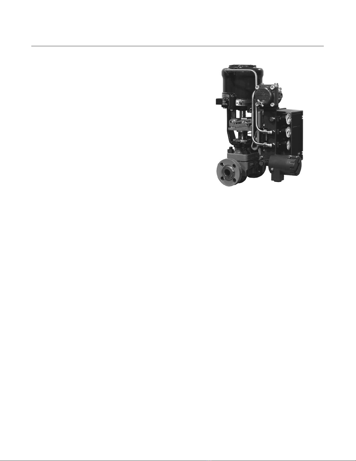
W6594 / IL
Figure 2. 3621JP Positioner with 585C Actuator
3620J, 3620JP, and 3621JP). This manual also
provides field installation information for the 3622
electro-pneumatic converter. Refer to separate
instruction manuals for information on the actuator
and control valve. Contact your Emerson Process
Managementtsales office if assistance is needed
in obtaining actuator or control valve instruction
manuals.
Do not install, operate or maintain a 3610J or 3620J
Series positioner without first Dbeing fully trained
and qualified in valve, actuator and accessory
installation, operation and maintenance, and D
carefully reading and understanding the contents of
this manual. If you have any questions about these
instructions, contact your Emerson Process
Management sales office.
Description
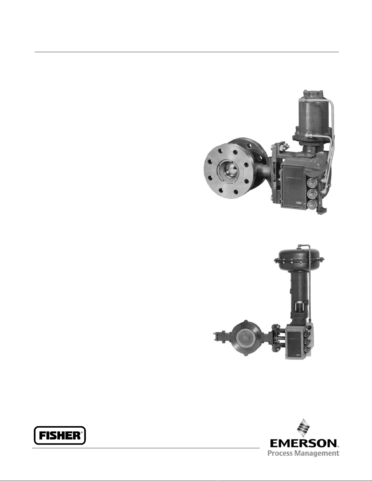
3610J or 3610JP pneumatic positioners and 3620J
or 3620JP electro-pneumatic positioners are used
with diaphragm rotary actuators and piston rotary
actuators as shown in figure 1. 3611JP and 3621JP
positioners are used with 585, 585R, 585C, or
585CR sliding stem actuators as shown in figure 2.
The positioner mounts integrally to the actuator
housing and provides a valve ball, disk, or plug
position for a specific input signal. The positioner
accepts either a pneumatic or milliampere input
signal. Refer to the Type Number Description for a
detailed explanation of type numbers.

3610J and 3620J Positioners
Instruction Manual
June 2008
3
Table 1. Specifications
Unless otherwise specified, the specifications
listed are for all positioner type numbers
Available Configurations
Refer to the type number description
Input Signal
3610J, 3610JP, and 3611JP: Standard: J0.2 to
1.0 bar (3 to 15 psig), J0.4 to 2.0 bar (6 to 30
psig), or Jsplit range, see table 12
Adjustable: Zero is adjustable from 0.07 to 1.5 bar
(1 to 22 psig) for standard valve rotations or valve
travels. Span is adjustable from 0.2 to 2.0 bar (3.2
to 28.8 psi) for standard valve rotations or valve
travels. Adjustment locations are shown in
figure 13.
3620J, 3620JP, and 3621JP: 4 to 20 mA DC
constant current with 30 VDC maximum
compliance voltage. Minimum terminal voltage is
2.4 VDC at 20 mA. Split range is also available,
see table 12.
Equivalent Circuit
3620J, 3620JP, and 3621JP: 120 ohms shunted
by three 5.6 V zener diodes
Output Signal
Pneumatic pressure as required by the actuator
up to full supply pressure
Action(1):Field-reversible between Jdirect and
Jreverse within the pneumatic positioner
Typical Performance for 3610J, 3610JP, 3620J,
and 3620JP Positioners with 1051, 1052, and
1061 Actuators
Independent Linearity
Direct-Acting 3610J and 3620J: ±1.5% of output
span
Reverse-Acting 3610J and 3620J: ±0.75% of
output span
Direct-Acting 3610JP and 3620JP: ±1.25% of
output span
Reverse-Acting 3610JP and 3620JP: ±0.5% of
output span
Hysteresis
3610J: 1.0% of output span
3620J: 0.75% of output span
3610JP: 0.5% of output span
3620JP: 0.6% of output span
Deadband: 0.1% of input span
Refer to table 3 for typical performance for
3611JP and 3621JP Positioners
Electromagnetic Interference (EMI)
3620J, 3620JP, 3621JP and 3622: Tested per
IEC 61326-1 (Edition 1.1). Meets emission limits
for Class A equipment (industrial locations) and
Class B equipment (domestic locations). Meets
immunity requirements for industrial locations
(Table A.1). Immunity performance is shown in
table 2.
Maximum Supply Air Demand(2)
3610J and 3620J:
1.4 bar (20 Psig) Supply: 13 normal m3/hour
(490 scfh)
2.4 bar (35 Psig) Supply: 17 normal m3/hour
(640 scfh)
3610JP, 3620JP, 3611JP, and 3621JP:
5.2 Bar (75 Psig) Supply: 37 normal m3/hour
(1380 scfh)
6.9 Bar (100 Psig) Supply: 46 normal m3/hour
(1700 scfh)
Operating Influences for 3610J, 3610JP, 3620J,
and 3620JP
Supply Pressure Sensitivity: A 10% change in
supply pressure changes the valve shaft position
less than the following percentages of valve
rotation:
3610J and 3620J: 1.0% at 1.4 bar (20 psig)
supply pressure
3610JP and 3620JP: 1.5% at 4.1 bar (60 psig)
supply pressure
Supply Pressure(3)
Minimum Recommended: 0.3 bar (5 psig) above
actuator requirement [1.4 bar (20 psig) for a 0.2 to
1.0 bar (3 to 15 psig) nominal actuator signal; 2.4
bar (35 psig) for a 0.4 to 2.0 bar (6 to 30 psig)
nominal actuator signal]
Maximum: 10.3 bar (150 psig) or maximum
pressure rating of the actuator, whichever is
lower.
Supply Medium: Air or natural gas(4)
3620J, 3620JP, 3621JP positioners and the
3622 electro-pneumatic converter are not
approved for use with natural gas as the
supply medium.
−Continued -

3610J and 3620J Positioners
Instruction Manual
June 2008
4
Table 1. Specifications (Continued)
Steady-State Air Consumption(2)
3610J: 0.40 normal m3/hour (15 scfh) at 1.4 bar
(20 psig) supply pressure
3610JP: 0.64 normal m3/hour (24 scfh) at 6.9 bar
(100 psig) supply pressure
3620J: 0.49 normal m3/hour (18.2 scfh) at 1.4 bar
(20 psig) supply pressure
3620JP: 0.93 normal m3/hour (35.0 scfh) at 6.9
bar (100 psig) supply pressure
Operative Temperature Limits(3)
−40 to 82_C (−40 to 180_F)
Hazardous Area Classification for 3610J, 3610JP,
and 3611JP
Complies with the requirements of ATEX Group II
Category 2 Gas and Dust
Electrical Classification for 3620J, 3620JP, and
3621JP
Hazardous Area:
Explosion proof, Dust-Ignition proof,
DIV 2, Intrinsic Safety, Type n
APPROVED
Explosion proof, Dust-Ignition proof,
Non-incendive, Intrinsic Safety, Type n
ATEX Intrinsic Safety, Type n, Flameproof
(Gas Atmospheres Only)
SAA Intrinsic Safety, Type n, Flameproof
Refer to Special Instructions for “Safe Use” and
Installation in Hazardous Locations, tables 4, 5, 6,
and 7 and figures 31, 32, 33, 34, and 35 for
additional information.
Housing Classification for 3620J, 3620JP, and
3621JP
CSA Type 3 Encl., NEMA 3, IP54 per IEC 60529;
Instrument should be mounted with vent on side
or bottom to meet weatherproofing classification
Pressure Connections
1/4 NPT internal
Conduit Connection for 3620J, 3620JP, and
3621JP
1/2 NPT internal (standard), M20 or PG13
adapter (optional)
Rotary Valve Rotation
60, 75, or 90 degrees
Sliding Stem Valve Travel
mm Inches
11
19 to 51
29 to 51
51 to 102
0.4375
0.75 to 2
1.125 to 2
2 to 4
Approximate Weight
3610J Series: 2.5 kg (5.6 pounds)
3620J Series: 3.6 kg (8.0 pounds)
Declaration of SEP
Fisher Controls International LLC declares this
product to be in compliance with Article 3
paragraph 3 of the Pressure Equipment Directive
(PED) 97 / 23 / EC. It was designed and
manufactured in accordance with Sound
Engineering Practice (SEP) and cannot bear the
CE marking related to PED compliance.
However, the product may bear the CE marking
to indicate compliance with other applicable
European Community Directives.
NOTE: Specialized instrument terms are defined in ANSI/ISA Standard 51.1 −Process Instrument Terminology.
1. For direct action, an increasing input signal extends actuator rod. For reverse action, an increasing input signal retracts actuator rod.
2. Normal m3/hr—Normal cubic meters per hour (0_C and 1.01325 bar, absolute). Scfh—Standard cubic feet per hour (60_F and 14.7 psia).
3. The pressure and temperature limits in this document, and any applicable code or standard should not be exceeded.
4. Natural gas should contain no more than 20 ppm of H2S.
Table 2. EMC Immunity Performance Criteria for 3620J, 3620JP, 3621JP and 3622
Port Phenomenon Basic Standard Test Level Performance Criteria(1)
Enclosure
Electrostatic Discharge (ESD) IEC 61000-4-2 4 kV contact; 8 kV air A
Radiated EM field IEC 61000-4-3 80 to 1000 MHz @ 10V/m with 1 kHz AM at 80% A
Rated power frequency magnetic field IEC 61000-4-8 60 A/m at 50 Hz A
I/O signal/control
Burst IEC 61000-4-4 1 kV A
Surge IEC 61000-4-5 1 kV (line to ground only, each) B
Conducted RF IEC 61000-4-6 150 kHz to 80 MHz at 3 Vrms A
Specification limit = ±1% of span
1. A= No degradation during testing. B= Temporary degradation during testing, but is self-recovering.

3610J and 3620J Positioners
Instruction Manual
June 2008
5
Table 3. Typical Performance Specifications(1) for 3611JP and 3621JP Positioners with 585, 585R, 585C, and 585CR Actuators
Characteristic 585C and 585CR
Size 25 Actuator(2) 585C and 585CR
Size 50 Actuator(2)
585 and 585R
Size 100 Actuator
Standard
585 and 585R
Size 100 Actuator
with Boosters(3)
Deadband(1) 0.1% of input span 0.1% of input span 0.1% of input span 0.1% of input span
Step Response(1,4,5) 0.3 seconds 0.3 seconds 2 seconds 0.3 seconds
Steady-State Air Consumption(6,7) 0.01 normal m3/min
(0.4 scfm)
0.01 normal m3/min
(0.4 scfm)
0.01 normal m3/min
(0.4 scfm)
0.01 normal m3/min
(0.4 scfm)
Hysteresis(3) 0.5% of output span 0.5% of output span 0.5% of output span 0.5% of output span
Terminal-Based Linearity(8) 1% of output span 1% of output span 1% of output span 1% of output span
Frequency Response(1) (−6 dB) 2 Hz 2 Hz 0.2 Hz 2 Hz
Supply Pressure Sensitivity 10% change in supply pressure changes the actuator stem position less than 0.1%
1. Performance tests are based on 6.9 bar (100 psig) supply pressure and lightest actuator springs. Performance will vary with other pressures and springs.
2. Size 25 and 50 actuators tested with appropriate parallel flexure (key 179).
3. Equipped with two 2625 boosters with 1/2 inch supply and exhaust ports.
4. Step response is the time for the actuator to reach 63 percent of expected travel after a 10 percent step change in input signal.
5. 3621JP positioner step response equals 0.4 seconds.
6. At 6.9 bar (100 psig) supply pressure. Normal m3/min-cubic meters per minute (0_C and 1.01325 bar). Scfm--standard cubic feet per minute (60_F and 14.7 psia).
7. 3621JP positioner steady-state air consumption equals 0.02 normal m3/min (0.58 scfm).
8. 3621JP positioner terminal-based linearity equals ±2.25%.
Type Number Description
The following descriptions provide specific
information on the different positioner constructions.
If the type number is not known, refer to the
nameplate on the positioner. For the nameplate
location, refer to key 157, figure 25.
3610J: A single-acting pneumatic rotary valve
positioner for use with 1051 and 1052 actuators.
3610JP: A double-acting pneumatic rotary valve
positioner for use with 1061 and 1069 actuators.
3611JP: A double-acting pneumatic sliding stem
valve positioner for use with 585, 585R, 585C, and
585CR actuators.
3620J: A single-acting electro-pneumatic rotary
valve positioner for use with 1051 and 1052
actuators.
3620JP: A double-acting electro-pneumatic rotary
valve positioner for use with 1061 and 1069
actuators.
3621JP: A double-acting electro-pneumatic sliding
stem valve positioner for use with 585, 585R, 585C,
and 585CR actuators.
3622: An electro-pneumatic converter used for
conversion of a 4 to 20 milliampere DC input signal
to a 0.2 to 1.0 bar (3 to 15 psig) input signal for the
pneumatic positioner. Use this unit in combination
with a 3610J, 3610JP, or 3611JP positioner to make
a 3620J, 3620JP or a 3621JP positioner.
Specifications
WARNING
This product is intended for a specific
range of pressure, temperatures and
other application specifications.
Applying different pressure,
temperature and other service
conditions could result in malfunction
of the product, which could cause
property damage or personal injury.
Specifications for the valve positioners are shown in
table 1. Performance specifications for 3611JP and
3621JP positioners are shown in table 3.
Educational Services
For information on available courses for 3610J and
3620J positioners, as well as a variety of other
products, contact:
Emerson Process Management
Educational Services, Registration
P.O. Box 190; 301 S. 1st Ave.
Marshalltown, IA 50158−2823
Phone: 800−338−8158 or
Phone: 641−754−3771
FAX: 641−754−3431
e-mail: [email protected]

3610J and 3620J Positioners
Instruction Manual
June 2008
6
Installation
Normally, a positioner is shipped with the actuator. If
so, the factory mounts and calibrates the positioner
and connects the positioner to actuator tubing. If the
positioner is ordered separately from the actuator,
perform the appropriate mounting procedure, and
follow the Calibration procedures in this instruction
manual. Refer to the appropriate instruction manuals
for actuator and valve mounting procedures.
WARNING
Avoid personal injury from sudden
release of process pressure. Before
mounting the positioner:
DAlways wear protective clothing
gloves, and eyewear when performing
any installation operations to avoid
personal injury.
DWhen installing 3620J Series
positioners in a hazardous area, turn
off control signals until installation is
complete. Be sure all safety barriers,
connections, and the converter
housing cap and O-ring are properly
installed before applying a control
signal to the unit.
DIf installing into an existing
application, also refer to the WARNING
at the beginning of the Maintenance
section.
DCheck with your process or safety
engineer for any additional measures
that must be taken to protect against
process media.
WARNING
Personal injury or property damage
may result from fire or explosion if
natural gas is used as the supply
medium and preventive measures are
not taken. Preventive measures may
include: Remote venting of the unit,
re-evaluating the hazardous area
classification, ensuring adequate
ventilation, and the removal of any
ignition sources.
3620J, 3620JP, 3621JP positioners and
the 3622 electro-pneuamtic converter
do not meet third party approvals for
use with natural gas as the supply
medium. Use of natural gas as the
supply medium can result in personal
injury or property damage from fire or
explosion.
Special Instructions for “Safe Use” and
Installation in Hazardous Locations
Certain nameplates may carry more than one
approval, and each approval may have unique
installation/wiring requirements and/or conditions of
“safe use”. These special instructions for “safe use”
are in addition to, and may override, the standard
installation procedures. Special instructions are
listed by approval.
WARNING
Failure to follow these conditions of
“safe use” could result in personal
injury or property damage from fire or
explosion, and area re-classification.
CSA
3620J, 3620JP, and 3621JP
Special Conditions of Use
No conditions of safe use.
Refer to table 4 for additional information, figure 31
for CSA loop schematics, and figure 32 for the
CSA/FM approvals nameplate.
FM
3620J, 3620JP, and 3621JP
Special Conditions of Use
No conditions of safe use.
Refer to table 5 for additional information, figure 33
for the FM loop schematic, and figure 32 for the
CSA/FM approvals nameplate.

3610J and 3620J Positioners
Instruction Manual
June 2008
7
Table 4. Hazardous Area Classifications for 3620J, 3620JP, and 3621JP—CSA (Canada)
Certification Body Certification Obtained Entity Rating Temperature Code Enclosure Rating
CSA
(Intrinsic Safety)
Zone
Ex ia IIC T4/T5/T6 per drawing GE28591
Class/Division
Class I, II Division 1 GP A,B,C,D,E,F,G
T4/T5/T6 per drawing GE28591
Vmax = 30 VDC
Imax = 150 mA
Pi= 1.25 W
Ci= 0 nF
Li= 0 mH
T4 (Tamb v82°C)
T5 (Tamb v62°C)
T6 (Tamb v47°C)
CSA Type 3 Encl.
(Explosion Proof)
Zone
Ex d IIC T5
Class/Division
Class I, Division I, GP A,B,C,D T5
−−−T5 (Tamb v82°C) CSA Type 3 Encl.
(Type n)
Zone
Ex nA IIC T6
−−−T6 (Tamb v82°C) CSA Type 3 Encl.
Class I, Division 2, GP A,B,C,D T6
−−−
T6 (Tamb v82°C)
CSA Type 3 Encl.
Class II, Division 1, GP E,F,G T5 T5 (Tamb v82°C)
Class II, Division 2, GP F,G T6 T6 (Tamb v82°C)
Table 5. Hazardous Area Classifications for 3620J, 3620JP, and 3621JP—FM (United States)
Certification Body Certification Obtained Entity Rating Temperature Code Enclosure Rating
FM
(Intrinsic Safety)
Zone
Class 1 Zone 0 AEx ia IIC T4/T5/T6
per drawing GE28590
Class/Division
Class I, II, III Division 1 GP A,B,C,D,E,F,G
T4/T5/T6 per drawing GE28590
Vmax = 30 VDC
Imax = 150 mA
Pi= 1.25 W
Ci= 0 nF
Li= 0 mH
T4 (Tamb v82°C)
T5 (Tamb v62°C)
T6 (Tamb v47°C)
NEMA 3, IP54
(Explosion Proof)
Zone
Class 1 Zone 1 AEx d IIC T5
Class/Division
Class I, Division I, GP A,B,C,D T5
−−−T5 (Tamb v82°C) NEMA 3, IP54
(Type n)
Zone
CL 1 Zone 2 AEx nA IIC T5
−−−T5 (Tamb v82°C) NEMA 3, IP54
Class I, Division 2, GP A,B,C,D T5
Class II, Division 1, GP E,F,G T5
Class II, Division 2, GP F,G T5
−−−NEMA 3, IP54
ATEX Intrinsic Safety
3620J, 3620JP, and 3621JP
Special Conditions of Use
This equipment is intrinsically safe and can be used
in potentially explosive atmospheres.
The electrical parameters of certified equipment
which can be connected to the device must not
exceed the following values:
U0v30 VDC
I0v150 mA
P0v1.25 W
Ambient temperature:
T6, at Tamb = 47_C
T5, at Tamb = 62_C
T4, at Tamb = 82_C
Refer to table 6 for additional information, and
figure 34 for the ATEX approvals nameplate.
ATEX Type n
3620J, 3620JP, and 3621JP
Special Conditions for Safe-Use
No conditions of safe use.
Refer to table 6 for additional information, and
figure 34 for the ATEX approvals nameplate.

3610J and 3620J Positioners
Instruction Manual
June 2008
8
Table 6. Hazardous Area Classifications for 3620J, 3620JP, and 3621JP—ATEX
Certificate Certification Obtained Entity Rating Temperature Code Enclosure Rating
ATEX
II 1 G
Gas
EEx ia IIC T4/T5/T6—Intrinsic Safety
Ui= 30 VDC
Ii= 150 mA
Pi= 1.0 W
Ci= 0 nF
Li= 0 mH
T4 (Tamb v82°C)
T5 (Tamb v62°C)
T6 (Tamb v47°C)
IP54
II 2 G
Gas
EEx d IIB T5/T6 —Flameproof
−−−T5 (Tamb v82°C)
T6 (Tamb v74°C) IP54
II 3 G
Gas
EEx nA IIC T6 —Type n
−−−T6 (Tamb v82°C) IP54
Table 7. Hazardous Area Classifications for 3620J, 3620JP, and 3621JP—SAA (Australia)
Certification Certification Obtained Temperature Code Enclosure Rating
SAA
Ex ia IIC —Intrinsic Safety T4 (Tamb v82°C) IP54
Ex n IIC —Type n T4 (Tamb v82°C) IP54
Ex d IIB —Flameproof T6 (Tamb v82°C) IP54
ATEX Flameproof
3620J, 3620JP, and 3621JP
Special Conditions for Safe-Use
Electrical connections are typically made using
either cable or conduit.
DIf using a cable connection, the cable entry
device shall be certified in type of explosion
protection flameproof enclosure “d”, suitable for the
conditions of use and correctly installed.
For ambient temperatures over 70_C, cables and
cable glands suitable for at least 90_C shall be used.
DIf using a rigid conduit connection, an EEx d
certified sealing device such as a conduit seat with
setting compound shall be provided immediately to
the entrance of the enclosure.
For ambient temperatures over 70_C, the wiring and
setting compound in the conduit seal shall be
suitable for at least 90_C.
Refer to table 6 for additional information, and
figure 34 for the ATEX approvals nameplate.
SAA Intrinsic Safety/Type n
3620J, 3620JP, and 3621JP
Conditions of Certification
1. It is a condition of safe use that the following
parameters are taken into consideration during
installation when the equipment is used as an EX ia
apparatus:
Input Parameters 2-Way Terminal Block
Maximum Input Voltage Ui
Maximum Input Current Ii
Maximum Internal Capacitance Ci
Maximum Internal Inductance Li
32 V
150 mA
0 μF
0 mH
2. It is a condition of safe use that the input voltage
does not exceed 32 Volts when the equipment is
used as an Ex n apparatus.
3. It is a condition of safe use that the equipment
shall be mounted such that the exhaust vents will be
self-draining.
4. It is a condition of safe use that the cable gland or
conduit adaptor with an ingress protection rating of
IP54 must be used in the conduit entry in order to
maintain the IP rating of the enclosure.
5. It is a condition of safe use that the irrelevant
explosion protection marking codes on the
certification label are permanently scribe off upon
completion of commissioning.
Refer to table 7 for additional information, and
figure 35 for the SAA approvals nameplate.
SAA Flameproof
3620J, 3620JP, and 3621JP
Conditions of Certification
1. It is a condition of safe use that the enclosure
must be connected to external circuits via Standards
Australia certified Ex d cable gland or conduit
adaptor with a minimum rating of IP54.

3610J and 3620J Positioners
Instruction Manual
June 2008
9
2. It is a condition of safe use that the equipment
must be mounted in position between upward and
horizontal such that the vent is facing downwards or
horizontally.
3. It is a condition of safe use that the irrelevant
explosion protection marking codes on the
certification label are permanently scribed off upon
completion of commissioning.
Refer to table 7 for additional information, and
figure 35 for the SAA approvals nameplate.
Mounting 3610J, 3610JP, 3620J, and
3620JP Positioners
During the following mounting procedures, refer to
figure 3 for part locations. Refer to figure 28 for key
number locations unless otherwise indicated.
1. Mark the positions of the travel indicator and
actuator cover. Then, remove the actuator travel
indicator machine screws, travel indicator, and
actuator cover cap screws.
2. Remove the positioner plate from the actuator
housing.
3. For actuator styles A and D, proceed to the note
before step 7. For actuator styles B and C, continue
with step 4.
4. Disconnect the actuator turnbuckle from the lever
arm.
Note
Do not change the position of the rod
end bearing on the end of the
turnbuckle.
5. Loosen the lever clamping bolt in the lever.
6. Mark the lever/valve shaft orientation, and
remove the lever.
Note
Cams A, B, and C have the letter D
(direct acting) on one side and the
letter R (reverse acting) on the other
side. Always install the cam with the
letter D on the same side as the cam
mounting screw heads (key 83,
figure 3).
7. Install the desired cam (key 82) on the actuator
lever with the cam mounting screws (key 83). Cams
B and C use the cam adjustment indicator (key 84)
between the screw heads and the cam. Align the
cam adjustment indicator with the desired total valve
rotation indication on the cam. Cam A does not use
the cam adjustment indicator and does not require
adjustment.
8. For actuator styles A and D, proceed to step 11.
For actuator styles B and C, continue with step 9.
9. Slide the lever/cam assembly (cam side first)
onto the valve shaft. Orient the lever with the shaft
as noted in step 6, and tighten the lever clamping
bolt.
Note
Refer to the appropriate actuator
instruction manual to determine the
distance required between the housing
face and the lever face and to
determine the proper tightening torque
for the lever clamping bolt.
10. Connect the turnbuckle and the lever arm.
11. Remove the positioner cover (key 41) from the
positioner. Slide the positioner into the actuator
housing so the cam roller (key 39) rests on the cam.
Insert and tighten the socket head screws (key 54)
to secure the positioner to the actuator housing.
12. Replace the actuator cover and the travel
indicator in the positions that were marked in step 1.
CAUTION
To avoid parts damage, do not
completely stroke the actuator while
the actuator cover is removed.
WARNING
To avoid personal injury from moving
parts, keep fingers and tools clear
while stroking the actuator with the
cover removed.
Note
To aid cover alignment on 1051 and
1052 actuators, use a regulated air
source to move the actuator slightly
away from its upper travel stop. If hole
alignment is still not possible,
temporarily loosen the cap screws that
secure the housing to the mounting
yoke, and shift the housing slightly.

3610J and 3620J Positioners
Instruction Manual
June 2008
10
TRAVEL INDICATOR
ACTUATOR
COVER
POSITIONER
PLATE
LEVER ARM
ROLLER (KEY 39)
POSITIONER COVER
(KEY 41)
FEEDBACK LEVER
ASSEMBLY (KEY 117)
CAM MOUNTING
MACHINE
SCREWS (KEY 83)
CAM ADJUSTMENT INDICATOR
(KEY 84, NOT USED ON CAM A) CAM
(KEY 82)
FEEDBACK
LEVER
ASSEMBLY
(KEY 117)
ACTUATOR WITHOUT POSITIONER
ACTUATOR AND POSITIONER WITH ACTUATOR COVER REMOVED
STYLE A OR D
STYLE B OR C
48A7851−C
14A7222−G14A7224−D
11B4045−A
58A7810−W
C0572−2/IL
ACTUATOR
ROD
TURNBUCKLE
SPLINED END
OF SHAFT
LEVER CLAMPING
BOLT
CAM (KEY 82)
Figure 3. Typical Mounting Details for 3610J and 3620J Series Positioners on Rotary Actuators
Changing Cams—Actuator Styles A, B,
C, and D
During the following procedures, refer to figure 3 for
part locations and refer to figure 28 for key number
locations unless otherwise indicated.
1. Mark the positions of the travel indicator and
actuator cover. Then, remove the actuator travel
indicator machine screws, travel indicator, and
actuator cover cap screws.
2. Remove the positioner plate from the actuator
housing.
3. For actuator styles A and D, proceed to the note
before step 7. For actuator styles B and C, continue
with step 4.
4. Disconnect the actuator turnbuckle from the lever
arm.
Note
Do not change the position of the rod
end bearing on the end of the
turnbuckle.
5. Loosen the lever clamping bolt in the lever.

3610J and 3620J Positioners
Instruction Manual
June 2008
11
BUTTON HEAD
SCREW
(KEY 173)
POSITIONER
COVER (KEY 41)
CAPTIVE
COVER SCREWS
3611JP
POSITIONER
STEM
BRACKET SLOTS
FEEDBACK LEVER
ASSEMBLY (KEY
117 OR KEY 170)
POSITIONER
ADAPTER
(KEY 113)
49A3788-A
A3231-2 / IL
CONTROL VALVE ASSEMBLY WITH ACTUATOR FRONT YOKE COVER PLATE REMOVED
Figure 4. Typical Mounting Details for 3611JP and 3621JP Positioners on 585 Series Actuators
6. Mark the lever/valve shaft orientation, and
remove the lever.
Note
Cams A, B, and C have the letter D
(direct acting) on one side and the
letter R (reverse acting) on the other
side. Always install the cam with
the letter D on the same side as the
cam mounting screw heads (key 83,
figure 3).
7. Install the desired cam (key 82) on the actuator
lever with the cam mounting screws (key 83). Cams
B and C use the cam adjustment indicator (key 84)
between the screw heads and the cam. Align the
cam adjustment indicator with the desired total valve
rotation indication on the cam. Cam A does not use
the cam adjustment indicator and does not require
adjustment.
8. For actuator styles A and D, proceed to step 11.
For actuator styles B and C, continue with step 9.
9. Slide the lever/cam assembly (cam side first)
onto the valve shaft. Orient the lever with the shaft
as noted in step 6, and tighten the lever clamping
bolt.
Note
Refer to the appropriate actuator
instruction manual to determine the
distance required between the housing

3610J and 3620J Positioners
Instruction Manual
June 2008
12
face and the lever face and to
determine the proper tightening torque
for the lever clamping bolt.
10. Connect the turnbuckle and the lever arm.
11. Replace the actuator cover and the travel
indicator in the positions that were marked in step 1.
CAUTION
To avoid parts damage, do not
completely stroke the actuator while
the actuator cover is removed.
WARNING
To avoid personal injury from moving
parts, keep fingers and tools clear
while stroking the actuator with the
cover removed.
Note
To aid cover alignment on 1051 and
1052 actuators, use a regulated air
source to move the actuator slightly
away from its upper travel stop. If hole
alignment is still not possible,
temporarily loosen the cap screws that
secure the housing to the mounting
yoke, and shift the housing slightly.
Mounting 3611JP and 3621JP
Positioners on 585 and 585R Size 100
Actuators
Refer to figure 4 for part locations. Refer to figure 29
for key number locations unless otherwise indicated.
1. Refer to the appropriate actuator instruction
manual. Loosen the four screws, and remove the
front yoke cover plate from the actuator.
2. Stroke the actuator from the top stop to the
bottom stop, and record the travel distance.
3. Loosen the four captive cover screws and
remove the positioner cover (key 41, figure 28).
4. Refer to the appropriate actuator instruction
manual. Loosen the four screws, and remove the
actuator blanking plate.
5. Attach the positioner adapter (key 113) to the
actuator with four socket head screws (key 54).
6. Disconnect the positioner range spring (key 150,
figure 25) from the range spring hanger (key 130,
figure 25).
7. Attach the roller (key 175) and washers (key 184)
to the adjuster assembly (key 174) and secure with
the retaining ring (key 172).
8. Apply pressure to the actuator piston and move
the actuator to approximately the mid-travel position.
9. Install the positioner on the actuator so the
feedback lever assembly (key 170) is under the stem
bracket and secure the positioner to the adapter
(key 113) with the four socket head screws (key 54).
10. With the actuator still at mid-travel and the top
edge of the feedback lever assembly perpendicular
to the actuator stem, install the adjuster
assembly/roller in the appropriate stem bracket slot
with the button head screw (key 173) so the roller is
centered over the correct actuator travel marked on
the feedback lever assembly (key 170) as shown in
figure 4.
11. Tighten the button head screw (key 173) and
replace the range spring (key 150, figure 25).
12. For size 100 actuators with greater than a 51
mm (2-inch) travel, install the feedback lever spring
(key 185).
13. Replace the positioner cover.
14. Replace the front actuator cover plate.
15. Discard the actuator blanking plate and the four
screws.
Mounting 3611JP and 3621JP
Positioners on 585C and 585CR Size 25
and 50 Actuators
The 3611JP pneumatic positioner and the 3621JP
electro-pneumatic positioner can be mounted on
either a 585C or 585CR piston actuator. A positioner
adaptor (key 113) attaches to the back of the
positioner and serves as the interface to the
mounting bracket (key 194). Refer to the 585C and
585CR actuators instruction manual (part number
D102087X012) for additional information on the
actuator.

3610J and 3620J Positioners
Instruction Manual
June 2008
13
FEEDBACK
ROLLER
(KEY 175)
STEM BRACKET
(KEY 195)
HEX NUT
(KEY 197)
FEEDBACK ROLLER
BUTTON HEAD
SCREW
(KEY 173) HEX SOCKET
CAP SCREW
(KEY 54)
HEX NUT
(KEY 197)
POSITIONER MOUNTING
BRACKET
(KEY 194)
HEX HEAD
CAP SCREW
(KEY 196)
POSITIONER ADAPTOR
(KEY 113)
3621JP
POSITIONER
A6841 / IL
Figure 5. Typical Mounting Details for 3611JP and 3621JP Positioners on 585C Actuator
Refer to figure 5 for parts identification.
1. Stroke the actuator from the top stop to the
bottom stop, and record the travel distance.
2. Loosen the four captive cover screws and
remove the positioner cover (key 41, figure 28).
3. Mount the stem bracket (key 195) to the actuator
with two hex nuts (key 197).
4. Disconnect the positioner range spring (key 150,
figure 25) from the range spring hanger (key 130,
figure 25).
5. Attach the feedback roller (key 175) to the stem
bracket (key 195) with the button head screw
(key 173).
6. Attach the positioner adaptor (key 113) to the
mounting bracket (key 194) with four hex nuts
(key 197) and four hex socket cap screws (key 54).
7. Remove the positioner cover. Attach the 3611JP
or 3621JP positioner to the positioner
adaptor/mounting bracket assembly with four hex
socket cap screws (key 54).
8. Apply pressure to the actuator piston and move
the actuator to approximately the mid-travel position.
MOUNTING HOLES FOR SIZE 50 ACTUATOR
MOUNTING HOLES
FOR SIZE 25 ACTUATOR
MOUNTING BRACKET
SLOT
A6840/IL
Figure 6. Positioner Mounting Bracket
9. Thread one of the three hex head cap screws
(key 196) into the yoke leg threaded hole
approximately two (2) turns.

3610J and 3620J Positioners
Instruction Manual
June 2008
14
FLAPPER
OFFSET TAPER
STRAIGHT TAPER
3610JP, 3611JP,
3620JP AND 3621JP
POSITIONERS
3610J AND 3620J
POSITIONERS
36A5654-A
A3234-1/IL
Figure 7. Nozzle Block Assembly
10. Install the assembly from step 7 to the 585C
or 585CR actuator by sliding the mounting bracket
slot (see figure 6) onto the yoke leg cap screw. As
you attach this assembly to the actuator, center the
spring-loaded feedback arm under the feedback
roller (key 175) on the stem bracket (key 195). Align
the mounting bracket top holes (see figure 6) with
the cylinder holes and install the remaining two hex
head cap screws (key 196). Tighten all screws.
11. With the actuator still at mid travel and the top
edge of the feedback lever assembly perpendicular
to the actuator stem, install the adjuster
assembly/roller in the appropriate stem bracket slot
with the button head screw (key 173) so the roller
(key 175) is centered over the correct actuator travel
marked on the feedback lever assembly.
12. Tighten the feedback roller button head screw
(key 173) and replace the range spring (key 150,
figure 25).
13. Replace the positioner cover.
Installing the 3622 Electro-Pneumatic
Converter
If installing the converter on an existing pneumatic
positioner, refer to the Gauge Block Disassembly
procedures in the Maintenance section. The
converter module replaces the original pneumatic
gauge block. Refer to the 3622 Electro-pneumatic
Converter Assembly procedure to install the
converter. When calibrating the electro-pneumatic
positioner for a 4 to 20 milliampere DC input range,
use the range spring hole that corresponds to a 0.2
to 1.0 bar (3 to 15 psig) input range [0.8 bar (12
psig) span]. See tables 10 and 11 and figure 15 for
the range spring and range spring hole selection.
Changing Positioner Types
All 3610J and 3620J Series positioners have the
same basic construction. For 3611JP or 3621JP, a
parallel flexure (key 179, figure 13) is added (not
required on 585 size 100 actuator). When changing
positioner types, other parts may require changing,
such as the nozzle assembly (key 116, figure 25),
the feedback lever assembly (key 117 or 170, figure
29), and the range spring (key 150, figure 25). Refer
to the Parts List for part number identification.
Changing parts may require partial disassembly and
reassembly as described in the Maintenance
section. Figure 7 illustrates the slight difference in
nozzle assemblies between the single-acting (3610J
and 3620J) and double-acting (3610JP, 3620JP,
3611JP and 3621JP) positioners. See the Changing
Positioner Types procedure in the Maintenance
section for additional information.
Pressure Connections
WARNING
The positioner is capable of providing
full supply pressure to connected
equipment. To avoid personal injury or
equipment damage caused by parts
bursting from system overpressure,
make sure the supply pressure never
exceeds the maximum safe working
pressure of any connected equipment.

3610J and 3620J Positioners
Instruction Manual
June 2008
15
OUTPUT A
CONNECTION
(PLUGGED)
208
(8.19)
63.5
(2.50) GAUGE
BLOCK
INSTRUMENT
CONNECTION
OUTPUT A
CONNECTION
(PLUGGED ON
3610J)
OUTPUT B
CONNECTION
SUPPLY
CONNECTION
49.3
(1.94)
153.9
(6.06)
17.5
(0.69)
63.5
(2.50)
122.2
(4.81)
3622
100.1
(3.94)
208
(8.19)
208
(8.19)
63.5
(2.50) 63.5
(2.50)
103.9
(4.09)
GAUGE
BLOCK
31.8
(1.25)
BYPASS
VALVE
INSTRUMENT
CONNECTION
OUTPUT B
CONNECTION
111.3
(4.38)
SUPPLY
CONNECTION
OUTPUT A
CONNECTION
(PLUGGED ON
3620J)
OUTPUT B
CONNECTION
SUPPLY
CONNECTION
111.3
(4.38)
50.8
(2.00)
1/2 NPT
CONDUIT
CONNECTION
19A1442-D
19A1444-C 11B2612-E
C0681-3 / IL
TYPICAL 3610J SERIES POSITIONER WITHOUT BYPASS VALVE
3610J POSITIONER WITH BYPASS ASSEMBLY 3620J OR 3620JP POSITIONER
NOTE:
INSTRUMENT, OUTPUT, AND SUPPLY CONNECTIONS ARE 1/4 NPT mm
(INCH)
1
1
1
1
1
1
1
1
1
1
1
1
103.9
(4.09)
111.3
(4.38)
CENTERLINE
OF BODY
119.1
(4.69)
CENTERLINE
OF BODY
CENTERLINE
OF BODY
Figure 8. Typical Mounting Dimensions and Connections
To complete the installation of a 3610J or 3620J
Series positioner requires connecting tubing and
fittings between the positioner and the actuator. The
fittings, tubing, and mounting parts required depend
on the type number and optional equipment: such as
filter, regulator, and bypass valve. Positioner
pressure connection locations are shown in figure 8.
All pressure connections to the 3610J and 3620J
Series positioners are 1/4 NPT internal. Use 3/8-inch
tubing or 1/4-inch pipe for all tubing connections.
Refer to the Vent Connection section for remote vent
connections.

3610J and 3620J Positioners
Instruction Manual
June 2008
16
19A1486-C
11B2613-C
B2151-2 / IL
208
(8.19)
146
(5.75)
93.0
(3.66)
63.5
(2.50)
63.5
(2.50)
63.5
(2.50)
146
(5.75) 50.8
(2.00)
100
(3.95)
208
(8.19)
87.4
(3.44)
153.9
(6.06)
49.3
(1.94)
3621JP POSITIONER
3611JP POSITIONER
SUPPLY
CONNECTION
OUTPUT B
CONNECTION
1
1
SUPPLY
CONNECTION
OUTPUT B
CONNECTION
1
1
OUTPUT A
CONNECTION
1
INSTRUMENT
CONNECTION
1
OUTPUT A
CONNECTION
1
1/2 NPT
CONDUIT
CONNECTION
NOTE:
INSTRUMENT, OUTPUT, AND SUPPLY CONNECTIONS ARE 1/4 NPT
1
3622 I/P
CONVERTER
GAUGE
BLOCK
CENTERLINE
OF BODY
17.5
(0.69)
Figure 8. Typical Mounting Dimensions and Connections (Continued)
Supply Connection
WARNING
Severe personal injury or property
damage may occur from process
instability if the instrument supply
medium is not clean, dry and oil-free
air, or noncorrosive gas. While use
and regular maintenance of a filter that
removes particles larger than 40
microns in diameter will suffice in
most applications, check with an
Emerson Process Management field
office and industry instrument air
quality standards for use with
corrosive gas or if you are unsure
about the proper amount or method of
air filtration or filter maintenance.
WARNING
3620J, 3620JP, 3621JP positioners and
the 3622 electro-pneumatic converter
do not meet third party approvals for
use with natural gas as the supply

3610J and 3620J Positioners
Instruction Manual
June 2008
17
12B8050-A
A6081-1 / IL
GAUGE
STEM PROVIDED
WHEN GAUGE
IS SPECIFIED
BODY
BODY PROTECTOR
NOTE:
BODY PROTECTOR AND BODY NOT
REQUIRED WITH THE 3610J POSITIONER.
1
Figure 9. FlowScannertDiagnostic System Connections for
3610J and 3610JP Positioners
medium. Use of natural gas as the
supply medium can result in personal
injury or property damage from fire or
explosion.
Supply pressure must be clean, dry, and oil-free air
or noncorrosive gas. Use of a 67CFR Filter
Regulator, or equivalent, to filter and regulate supply
air should suffice in most applications. The 67CFR
filter regulator can be integrally mounted with the
positioner. Use 3/8-inch tubing or 1/4-inch pipe for
the supply line.
CAUTION
To avoid equipment damage caused
by excessive pressure, do not exceed
the maximum pressure rating of the
actuator or positioner. Refer to the
appropriate instruction manual to
determine the maximum pressure
rating of the actuator, and to table 1
for the maximum pressure rating of the
positioner.
The supply pressure should be high enough to
permit setting the regulator 0.3 bar (5 psi) above the
upper limit of the appropriate pressure range, for
example: 1.4 bar (20 psig) for a 0.2 to 1.0 bar (3 to
15 psig) range. However, do not exceed the
maximum allowable supply pressure of 10.3 bar
(150 psig) nor the pressure rating of any connected
equipment.
Output Connections
For the 3610J or 3620J positioner, the OUTPUT A
connection must be plugged. Connect the OUTPUT
B connection to the actuator diaphragm casing
12B8051-B
A6083-1 / IL
GAUGE
STEM PROVIDED
WHEN GAUGE
IS SPECIFIED
BODY
BODY PROTECTOR
NOTE:
BODY PROTECTOR AND BODY NOT
REQUIRED WITH THE 3620J POSITIONER.
1
Figure 10. FlowScannertDiagnostic System Connections for
3621J and 3620JP Positioners
connection. Figure 8 shows a positioner with a
bypass valve. When the bypass valve is used,
connect the OUTPUT connection on the bypass
valve to the diaphragm casing connection on the
actuator. A manifold in the bypass body adapter
internally connects OUTPUT B to the bypass valve.
Use 3/8-inch tubing between the actuator and the
positioner.
For the 3610JP or 3620JP positioner, connect the
OUTPUT A connection to the lower actuator cylinder
connection and the OUTPUT B connection to the
upper actuator cylinder connection. Figure 1 shows
the positioner connected to a piston actuator. Use
3/8-inch tubing between the actuator and positioner.
For the 3611JP or 3621JP positioner, connect the
OUTPUT A connection to the lower actuator cylinder
connection and the OUTPUT B connection to the
upper actuator cylinder connection. Figure 2 shows
the positioner connected to a 585C actuator. Use
3/8-inch tubing between the actuator and the
positioner.
Instrument Connection
Use 3/8-inch tubing to connect the output from the
control device to the INSTRUMENT connection on a
pneumatic positioner. For the electro-pneumatic
positioner, refer to the Electrical Connections
section.

3610J and 3620J Positioners
Instruction Manual
June 2008
18
A5577 / IL
EARTH
GROUND
TERMINAL
BLOCK
FIELD WIRING
−
CONVERTER
HOUSING
CONTROL
DEVICE
+
+
−
FOR TROUBLESHOOTING OR MONITORING OPERATION,
AN INDICATING DEVICE CAN BE A VOLTMETER ACROSS
A 250 OHM RESISTOR OR A CURRENT METER.
1
NOTE:
Figure 11. Typical Field Wiring Diagram
Diagnostic Connections
To support diagnostic testing of
valve/actuator/positioner/accessory packages,
special connectors and hardware are available. The
hardware used includes 1/8 NPT connector bodies
and body protectors. If the diagnostic connectors are
ordered for a positioner with gauges, 1/8-inch stems
are also included.
Install the connectors on the 3610J Series positioner
gauge block or bypass block assembly as shown in
figure 9. For 3620J Series positioners, install the
connectors on the 3622 housing as shown in figure
10. Before installing the connectors on the
positioner, apply sealant to the threads. Sealant is
provided with the diagnostic connections and
hardware.
Vent Connection
3610J and 3620J Series positioner relays exhaust
actuator pressure through the positioner case and
into the 1051, 1052, 1061, and 1069 actuator
housings. These actuator housings provide a 1/4
NPT connection and a screen is normally installed in
this connection to prevent blockage from debris or
insects. Restricting this vent area can produce a
pressure buildup in the case and degrade positioner
performance. There also is a 1/4 NPT connection on
the 3622 converter housing where the vent (key 28)
is installed. 585, 585R, 585C, and 585CR actuators
do not have a 1/4-inch vent connection.
4-20 mA
60 OHMS
60 OHMS
5.6 V 5.6 V 5.6 V
21B2335-D
A5578-1 / IL
Figure 12. 3622 Converter Equivalent Circuit
WARNING
Personal injury or property damage
could result from fire or explosion of
accumulated gas if a flammable gas is
used as the supply pressure medium
and the positioner/actuator is in an
enclosed area. The positioner/actuator
assembly does not form a gas-tight
seal, and a remote vent line is
recommended. However, a remote vent
line cannot be relied upon to remove
all hazardous gas, and leaks may still
occur. Provide adequate ventilation
and necessary safety measures. Vent
line piping should comply with local
and regional codes and should be as
short as possible with adequate inside
diameter and few bends to reduce
case pressure buildup.
WARNING
3620J, 3620JP, 3621JP positioners and
the 3622 electro-pneumatic converter
do not meet third party approvals for
use with natural gas as the supply
medium. Use of natural gas as the
supply medium can result in personal
injury or property damage from fire or
explosion.
If a remote vent is required, the vent line must be as
short as possible with a minimum number of bends
and elbows. Vent line piping should have a minimum
inside diameter of 19 mm (3/4 inches) for runs up to
6.1 m (20 feet) and a minimum inside diameter of 25
mm (1 inch) for runs from 6.1 to 30.5 meters (20 to
100 feet).
Other manuals for Fisher 3610J
1
This manual suits for next models
1
Table of contents
Other Emerson Valve Positioner manuals
Popular Valve Positioner manuals by other brands

Axis
Axis T99A Series installation guide

Baker Hughes
Baker Hughes Masoneilan SVi 1000 quick start guide

Spirax Sarco
Spirax Sarco SP7-11 Installation and maintenance instructions

Omron
Omron H8PS instruction manual

Baker Hughes
Baker Hughes Masoneilan SVI FF quick start

Radius
Radius RX-500 Series instruction manual