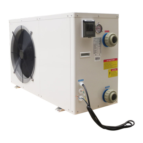
Ecoplus SWBM-10.5H-B/P-S User manual

Installation & Instruction Manual
LOW AMBIENT
HEAT PUMP WATER HEATER
MODEL:
SWBM-10.5H-B/P-S
SWBM-17.5H-B/P-S
SWBM-35.0H-B-S


Ⅰ.To our customers
Ⅱ.Product Introducing-----------------------------------------------------------------------2
Ⅲ.Work principle------------------------------------------------------------------------------3
Ⅳ.Performance Data--------------------------------------------------------------------------4
Ⅴ.Dimension------------------------------------------------------------------------------------5
Ⅵ.Operation introductions------------------------------------------------------------------8
Ⅶ.Wire Circuit Diagram--------------------------------------------------------------------14
Ⅷ.Installation instructions-----------------------------------------------------------------16
Ⅸ.Maintenance--------------------------------------------------------------------------------20
----------------------------------------------------------------------------1
CONTENTS
Water heater
Contents

Ⅰ.To our customers Water heater
1
Dear Sir:
In order to use this machine safely, please read this INTRUCTION MANUAL carefully
before using and installation. Heat pump water heater is a professional machine, it may
cause damage or hazard when wrong installed, it should be installed by a competent
person in accordance with the relevant standards for the country of use.
WARNING:
ELECTRICAL POWER MUST BE SWITCHED OFF
BEFORE STARTING ANY WORK ON JUNCTION BOXES
1.Before installing the heat pump, please ensure that the electrical supply corresponds
to the specification indicated on the unit's rating label before proceeding with the
connection in accordance with the wiring diagram supplied. Please check carefully
on the rating label and the wiring diagrams that pasted on each heat pump unit.
2.The unit must be EARTHED to avoid any risks caused by insulation defects. It is
forbidden to start any work on the electrical components without switching off the
electrical supply to the unit. Electric leakage switch protection device MUST be
installed.
3.It is forbidden to start any work on the electrical components if water or high
humidity is present on the installation site.
4.When the unit is being connected, ensure that no impurities are introduced into the
pipe work and the water circuits.
5.All maintenance or repair of the heat pump must be performed by competent
technicians.
6.It could be hurtful when generated hot water reaches 52 ℃, please mix with cold
water before using.
7. To prevent any damage to the fan or any accidents, it is forbidden to put your
fingers or any other objects into the air outlet. Kids or children should be kept
away from the heat pump.
8. This appliance is not intended for use by persons (including children) with
reduced physical, sensory or mental capabilities, or lack of experience and
knowledge, unless they have been given supervision or instruction concerning
use of the appliance by a person responsible for their safety.
9.Children should be supervised to ensure that they do not play with the appliance.

Ⅱ.Product Introducing Water heater
2
Product Introducing
Safe and Reliable
Unlike traditional electric water heater, heat pump water heater do not directly generate
heat by electricity , it use less electricity to move heat from one place to another , electric
circuit is separated from water circuit ,which is also not easy for electric shock,
inflammable , explosion and poisoning ! Safer and more reliable!
Highly efficient & Energy saving
Heat pump water heater absorb plenty of heat from free ambient air, and can supply same
hot water volume as electric heater. Electricity consumption is only 1/4 compared to
electric heater, very energy saving!
Environmental Friendly
Heat pump not only use less electricity to get heat from ambient air , but are also able to
combine using with solar equipment , will not cause pollution and no poison gas
exhausting .
All Round The Year Hot Water
Heat pump water heaters are not affected by seasonal climate, provide hot water all year
round even in cloudy or rainy days!
Durable and long-lasting time
Heat pump spare parts such as compressor and 4-way-valve are made by famous brand
manufacturer , and casing panel is corrosion resistance, very durable and long-lasting
time .
Convenient Installation
Installation site for heat pump can be the roof, the garage , the kitchen, the storing room ,
the basement and so on, very convenient on installation .
Wide Application
Heat pump water heaters are applicable for family, factory, school, hotel , hospital , and
laundry ,etc. Wide application for different using request.

Power supply Temp adjustor
90 Around℃
Condenser
Tap water 18 ℃
Hot water
Supply60℃
Compressor
Gas and liquid
separated controller
Air energy supply
Evaporator
Liquid tank Dry filter Expand valve
IC
Economizer
Swichable
maghtism
valve
Electronic
Expansion
Valve
Ⅲ.Work principle Water heater
3
Work principle
The low temperature and low pressure refrigerant gas come from the evaporate to the
compressor, After the compressor compress it , the refrigerant gas became high
temperature and high pressure.Then the gas come into the water condensation into
liquid, emit a lot of condensation heat,condensing heat absorbed by water, making the
water temperature increased, and then the liquid refrigerant come through the expansion
valve, with a fan , the evaporate heat in the air, after all evaporation , the low pressure
compressor refrigerant gas inhalation in the compressor, after working through the
compressor, a high temperature and high pressure of the refrigerant gas from the
compressor to exhaust emissions, such reciprocating cycle.

Performance Data
Measuring conditions:
Heating: dry bulb 7℃, wet bulb 6℃, water inlet 40℃,water outlet 45℃ .
Ⅳ.Performance Data Water heater
Model
Rated Heating Capacity BTU/h
KW
Power Supply
Compressor Type
Compressor Nos.
Fan Motor Nos.
Fan Motor Input
Fan Speed
Noise
Water Connections
Water Flow Volume
Water Pressure Drop
L
W
H
Paking
Dimension
Net Weight
Gross Weight
Unit
Dimension
L
W
H
Weight kg
Kpa
Water pump Power
Head M
KW
RPM
dB(A)
inch
3
m /h
mm
mm
W
V/PH/Hz
COP W/W
Running Current Heating A
Heating Input Power W
Scroll
SWBM-17.5H-B/P-S
17.5
60000
4800
7.6×3
3.7
380/3/50
1
2
360
1380
56
1
4.5
34
1.0
20
1300
500
1370
1440
570
1550
160
215
SWBM-35.0H-B-S
35
120000
9700
15.3×3
3.6
380/3/50
2
4
720
1380
58
1.5
10
34
--
--
1508
590
1850
1650
650
2030
235
325
4
SWBM-10.5H-B/P-S
10.5
36000
2800
4.5×3
3.7
380/3/50
1
1
180
1380
54
1
2.3
34
0.5
16
900
500
1510
1070
590
1700
100
130

Water heater
Ⅴ.Dimension
Measure: mm
The dimension for air source heat pump water heater
SWBM-10.5H-B/P-S
5
804
1510
1362
565
460
420
500

Measure: mm
The dimension for air source heat pump water heater
SWBM-17.5H-B/P-S
low ambient
Ⅴ.Dimension Water heater
6
1300
765
420
1370
460
500

The dimension for low ambient air source heat pump water heater
SWBM-35.0H-B-S
Ⅴ.Dimension Water heater
Measure: mm
7
1850
1580 508
1790
880
460
500

Operation introductions
1. Initialization
◎ Under start-up state, LCD screen left side displays the water inlet setting temperature,
right side displays the actual water inlet temperature ; Under stand-by state, LCD main
interface only displays the actual water inlet temperature on the right side .
◎ Under start-up state, LCD screen displays heating symbol ; Stand-by state , LCD
screen does not display heating symbol ;Defrosting state, flashes
◎ When setting the time of Timer On / Timer Off , LCD screen displays timer symbol
"ON""OFF".
2. Definition of LCD Controller Buttons.
2.1 " "for ON /OFF and Return
2.1.1 On main interface, Press “ ” to turn on or turn off the heat pump.
2.1.2 After entering parameter or clock setting, press “ ” once to return to
main interface.
Start-up state
Stand by state
1
2
Initialization
Ⅵ.Operation introductions Water heater
2.2 " "for Status Inquiry
2.2.1 Press “ ”once to enter parameter inquiry,
2.2.2 Long press " " for 5 seconds to enter parameter setting status inquiry.
2.3 " "&" "for Up and Down
2.3.1 Under start-up state, press “ ” and “ ” to directly adjust/set the hot
water temperature .
2.3.2 Press“ ”and “ ”/ “ ”to check and adjust the parameters.
2.4 " "for Clock and Auxiliary Heater setting
2.4.1 Press “ ”once to enter Clock setting, meanwhile press “ ”/ “ ”
to adjust the time.
2.4.2 Long press “ ”for 5 seconds to switch on or off the auxiliary heater
function . When Auxiliary heater symbol “ ”is displayed, system allows
to start the Auxiliary heater function.
8

Operation introductions
Ⅵ.Operation introductions Water heater
2.5 " "for Timer
2.5.1 Press to enter the setting of Timer On and Timer Off (Totally you may set 3
sets of different Timer On and Timer Off), and press “ ”/ “ ” may
change the time, details see Timer On/Off setting.
3. Wire Controller Operation
3.1 Turn on and turn off the mp
3.1.1 Press “ ” once to turn on or turn off the heat pump.
3.2 Keyboard Lock & Unlock
3.2.1 Under unlocked state, press both “ ”and “ ” at the same time for 5
seconds, after “Dee — ”sound, keyboard is locked.
3.2.2 Under locked state, press both “ ”and “ ” at the same time for 5
seconds, after“Dee — ” sound, keyboard is unlocked.
heat pu
Clock setting
3.3 Clock Setting
3.3.1 On main interface, press “ ” once, to enter clock setting interface, at this
moment, the hour time for clock setting shows and flashes.
3.3.2 press “ ”and “ ”can set the hour time for clock.
3.3.3 After setting hour time, press“ ” once, then only minute time shows and
flashes, then you can press “ ”and“ ” to set the minute time for the clock.
3.3.4 After setting the minute time, press“ ” once to confirm and save all the setting
to current live clock time, meanwhile to exit the setting interface and return the
main interface.
Keyboard Lock
9

Operation introductions
Ⅵ.Operation introductions Water heater
3.4 Timer On & Timer Off Setting
3.4.1 On main interface, press“ ”to switch among 3 sets of Timer setting.
3.4.2 After entering the Timer On setting interface, press“ ”once to enter current
Timer On setting interface, at this moment, the hour time of clock shows and
flashes,press “ ” or “ ”to roll up or down to set/adjust the Timer On
hour time.
3.4.3 After setting hour time for the Timer, press“ ” once, only minute of the clock
shows and flashes, then press “ ” or “ ” to roll up or down to set the
timer on minute.
3.4.4 After setting the minutes, press“ ”once to confirm and save all the Timer On
setting ,and switch to Timer Off setting interface. At this moment, the hour of
clock shows and flashes, press“ ” or “ ” to roll up or down to set the Timer
Off hour .
3.4.5 After setting Timer Off hour, press“ ” once, only minute of the clock shows
and flashes, then press “ ”and“ ” to roll up and down to set the timer Off
minute.
3.4.6 After setting the Timer Off Minutes, press“ ” once, to confirm and save all the
setting for Timer On/Off and return to 3 sets Timer switching interface.
3.4.7 When the time for current set of Timer On and Timer Off is the same, system will
automatically cancel the Timer On /Timer Off function.
Timer on
setting
Timer off
setting
Timer setting
10

Operation introductions
Ⅵ.Operation introductions Water heater
Operation introductions
Ⅵ.Operation introductions Water heater
3.5 System Parameter & Status Inquiry
On main interface, press “ ” to enter the inquiry interface of temperature sensor
and electric expansion status, press“ ”and“ ”can check each parameter status.
3.5.1 Press “ ”for 5 seconds to check parameter setting value, press “ ” “ ”
to check each system's parameter setting value.
or
Parameter Content Range Default value Remark
Water in temperature sensor
Water out temperature sensor
Ambient temperature sensor
System 1- coil tube temperature
sensor
System 1- air exhausting
temperature sensor
System 2- air exhausting
temperature sensor
Electrical expansion valve
current steps
Reserved
Model parameter
-20~99℃
-20~99℃
-20~99℃
-20~99℃
-20~99℃
-20~90℃
0~125℃
0~125℃
150~450
0
20 ~60℃
1℃~20℃
15~90min
1℃~20℃
-30℃~0℃
1℃~30℃
30~90min
1~12min
15~45
100~125℃
0~1
50℃~60℃
20℃~40℃
℃40℃
5℃
30min
5℃
-3℃
14℃
45min
8min
25
110℃
1
60℃
35℃
00
01
02
03
04
05
06
07
08
09
10
20
21
22
23
24
25
26
27
28
29
30
31
32
Display also even
system is not start up
Actual testing
value
Actual testing
value
Actual testing
value
Actual testing
value
Actual testing
value
Actual testing
value
Actual testing
value
Actual testing
value
Actual testing
value
Actual testing
value
0/1/2/3
0 :for single phase power
single system,
1: for single phase power
dual system ,
2: for 3 phase power single
system,
3: for 3 phase power dual
system
Control
Parameter Meaning of Setting parameter Range Default Remark
Return water setting temperature
Heating temperature difference (heat pump)
Auxiliary heater starting delay time
Auxiliary heater return temperature difference
Temperature to enter defrosting
Temperature to exit defrosting
defrosting period
Max defrosting time
electric expansion valve initiate value
Air exhausting protection temperature value
Memory record for power disconnection
Second set point (mamimum setting temp range)
Second set point (minimum setting temp range)
Actual impulsion =
setting value*10
1 means record the memory
if any power disconnection
11
System 1- outlet
temperature sensor
Economizer
System 1-
temperature sensor
Economizer inlet
Only validity when S1 switch
connected
Only validity when S1 switch
connected

Operation introductions
Ⅵ.Operation introductions Water heater
3.6 System parameter setting
3.6.1 Under stand-by state, to check the Inquiry interface(see3.5.2), if current displayed
parameter are system parameter, press “ ” may enter to current parameter
setting interface.
3.6.2 On the interface of parameter setting, press “ ”or“ ” to adjust the current
system parameter setting value. After parameter value is set, press “ ”again
to save current setting value, and exit current parameter setting interface.
3.6.3 During the parameter setting , if not pressing any button within 10 seconds, system
automatically save current setting value , exit setting interface and return to main
interface. ess directly “ ” also return to main interface.
3.7 Any pressing on the LCD controller will lighten the background light, if no any
other operation within 10 seconds, background light will be off.
To pr button
15E:
temperature
sensor failure
Ambient
12
System parameter
setting
3.5.2 On the interface of Parameter and Status inquiry , if not pressing any button within
10 seconds, system automatically exit the inquiry interface and return to main
interface, To press directly “ ”ON/OFF or “ ” button also return to
main interface.
3.8 Setting about S1 & S2 switch
S1 Switch---Second Set Point
S2 Switch----Long distance demand
3.8.1 Second Set Point available when S1 switch has well connected.
At the same time, water temp set point setting decided by ambient temp, Parameter 31 and
Parameter 32. (Both 31 & 32 Parameter would be adjusted)
Parameter 31 (maximum setting range 50~60 °C)
Parameter 32 (minimum setting range 20~40 °C)
A. When ambient temp < 5°C, set point temp refer to the data of Parameter 31
B. When ambient temp >15°C, set point temp refer to the data of Parameter 32
C. When 5°C ≤ ambient temp ≤ 15°C, Set point temp = Data of Parameter 31- (Data of
parameter 31- data of parameter of 32)/(15-5)*(Ambient temp -5 )
For example, when ambient temp is 18 deg c, Parameter 31 data is 60 deg c, Parameter 32
data is 20 deg c.Then set point temp =60-(60-20)/(15-5)*(18-5)

Operation introductions
Ⅵ.Operation introductions Water heater
3.8.2 When S1 disconnected, set point temp control by LCD controller. (Refer to the setting of
Parameter 20 (default setting 40 deg c).
3.8.3 Heat pump will turn on when S2 switch has well connected.However, S2 well connected,
and suddenly press the off button on the LCD controller.Heat pump will stop for 3 minutes.
After 3 minutes heat pump continue to turn on if S2 Still has been connected.
3.8.4 The timer function is out of validity when S2 switch is connected.
3.8.5 Heat pump turns off when S2 switch is disconnected. Meanwhile, need to use LCD controller
to switch on/off the heat pump.
3.9 Failure code and parameter tables
Error
code Content
00E
01E
02E
03E
04E
05E
06E
07E
08E
09E
10E
11E
12E
13E
14E
15E
16E
17E
18E
19E
Remark
Communication failure
Water flow failure
System 1 compressor high pressure failure
System 1 compressor low pressure failure
System 1 compressor air exhausting temperature too high
power phase failure
Auxiliary heater temperature too high protection
System 2 compressor high pressure failure
System 2 compressor low pressure failure
System 2 compressor air exhausting temperature too high
First class anti-freezing protection
Second class anti-freezing protection
System 1- cold water out temperature sensor failure
System 1-cold water in temperature sensor failure
System 2- air exhausting temperature sensor failure
Ambient temperature sensor failure
Water outlet sensor failure
Return water temperature sensor failure
System 1- coil tube temperature sensor failure
System 1-air exhausting temperatures sensor failure
Main board(PCB)and wire controller
continuously lose signal connection
for 1 minute, error code shows but
unit non stop.
Single phase model excluded
Single system unit excluded
Single system unit excluded
Single system unit excluded
Single system unit excluded
13

Wire Circuit Diagram
Ⅶ.Wire Circuit Diagram Water heater
Applicable model: SWBM-10.5H-B/P-S SWBM-17.5H-B/P-S
Note: crank heaters marked in diagram are optional parts according to
customer request!
14
FM1
T
R
FM2
A
B
C
N1
N2
N3
3
N
T
R
S
T
R
S
380V/50Hz
CM
High Press Switch
Low Press Switch
Electric heater protect
Electric heater
Water flow
Water Pump
Compressor
4-way Valve
Fan Motor
Swichable
maghtism valve
Wire
Controller
Transformer
U
CONTACTOR 1
V
W
YLW/GRN
Ambient Temp
Economizer inlet Temp
Economizer outlet Temp
Compressor side air discharge Temp
Air fin evaporater coil tube Temp
Outlet Water Temp
Inlet Water Temp
CRANKSHAFT
HEATER
CHASSIS HEATER
LOW AMBIENT HEAT PUMP WIRING DIAGRAM
CZ1 CZ2 CZ3 CZ4 CZ5 CZ6 CZ7 CZ8 CZ9 CZ10
5
Electronic
Expansion
Valve
S
CONTACTOR 1
CONTACTOR 2
1 2 3 4 5 6
SW1 SW2
T1
T2
T3
T4
T5
T6
T7
T7 T6 T5 T4 T3 T2 T1
ON
1 2 1 2
ON
Second
set point
switch
Long distance
demand
7 8 9 10

Wire Circuit Diagram
Ⅶ.Wire Circuit Diagram Water heater
Applicable model: SWBM-35.0H-B-S
Note: crank heaters marked in diagram are optional parts according to
customer request!
15
Ambient Temp
Economizer inlet Temp
Economizer outlet Temp
Compressor side air discharge Temp. 1
Compressor side air discharge Temp. 2
Air fin evaporater coil tube Temp
Outlet Water Temp
Inlet Water Temp
T1
T2
T3
T4
T5
T6
T7
T8
380v/3Ph/50Hz
Y/G
S T N
RED
BLK
WHT
BLU
WHT
BLK
RED
CM1
R
RT
T
CONTACTOR COMPRESSOR
Y/G
Y/G
COM PRESSOR
CON TACTOR
CM2
S
S
R
S
T
R
Transformer
A
B
C
N1
N2
N3
3
High Press SwitchSYS1
High Press SwitchSYS2
SYS1 Low Press Switch
SYS2 Low Press Switch
Electric heater protect
Water flow
Wire
Controller
CZ1 CZ2 CZ3 CZ4 CZ5 CZ6 CZ7 CZ8 CZ9 CZ10
5 5
Electronic
Expansion
Valve 1
Electronic
Expansion
Valve 2
SW1 SW2
T8 T7 T6 T5 T4 T3 T2 T1
ON
1 2 1 2
ON
Economizer
maghtism valve
F M 3
F M 1 F M 4
F M 2
Fan Motor
Fan Motor
S
4-WAY1
4-WAY2
T
Swichable
maghtism valve
Swichable
maghtism valve
Swichable
maghtism valve
Swichable
maghtism valve
CONTACTOR 2
CONTACTOR 1
R
Electric heater
Water Pump
CRANKSHAFT
HEATER
CHASSIS HEATER
1 2 3 4 5 6 7 8 9 10 11 12 13 14
SWBM-35.0H-B-S
LOW AMBIENT HEAT PUMP WIRING DIAGRAM
Second
set point
switch
Long distance
demand
15 16 17 18

Installation instructions
1. Unit installation
1).Installation location
Host unit
1Should be installed in a larger & well-ventilated place.
1Installation location should ensure unhindered access outlet (inlet & outlet shown as
below).
1Install gutter or set up positions near the outfall, to facilitate the drainage.
1The installation base or bracket should be a steady, to ensure the smooth operation of
generating units.
1Make sure the unit is vertical after installation, and no incline.
1Make sure not to install the host unit in the any conditioner of pollution, corrosive gases,
sun and fallen leaves, etc.
1Installation location must not next to place of incendive , easy-explosion and fire .
1Installation must pay attention to the distance between the barriers shown in below
picture (pay attention to arrow direction).
Water tank
1Water tanks should be placed where ambient temperature is above 0℃ .
1Can be installed outdoors or the top of the building (based on the size of water tanks and
the load-bearing capacity of the building and so on).
1Do not have water tanks installed in the pollution, corrosive gases place.
2).Unit installation
1Units base can be installed as cement concrete structures, steel brackets can also be used,
add the shockproof rubber pads , make the base surface flat.
1Units can be designed based on the working performance.
(See Table of technical performance parameters)
1Unit should have drain or drainage inlets.
1Normally required to install in the place where setted cement concrete base.
Ⅷ.Installation instructions Water heater
16
1000mm above the top
Above 1000mm Above 1000mm
Above 1000mm
Air inlet
Air inlet Air inlet

Installation instructions
2. Pipeline connecting
Installation notes:
1Water drain pipes, overflow pipes should be installed next to the drainage inlets to
facilitate drainage, vent valve should be installed on vent pipes.
1Repair valve should be installed in front of the electromagnetic valve on the pipeline
system, which is convenient for future repair.
1User water pressure should less than 0. 6 Mpa.
1All pipelines should choose metal pipe (such as stainless steel, with Lining Plastic and
lining stainless steel and thin-walled copper pipe or, etc.). The use of plastic pipe
(such as the PP-R, ABS, etc.) should consider the pipeline expansion between the host
unit and water tanks .
1Water supply and pause valves may need to keep warm in the winter (according to the
local winter temperature) to avoid the broken of water supply and pause valve.
Water system installation
1All the pipeline tubing should be matched as shown on the manual, and in accordance
with national corresponding construction standards.
1Installation of water pipes should be straight and flat, pipeline collocation should be
rational, ensure to minimize bending; reduce the resistance loss of the water system.
1Pipeline and connecting parts are not allowed a leakage phenomenon.
1After the installation of circulating pipe between tap water pipes, host unit and water
tanks ,should carry out water leakage testing, and eject the sewage to ensure the sy
stem's cleanness.
1If no water leakage, keep the hot water pipe warm.
3. Project example:
Application of heat pump water heater engineering systems have different forms. Here
are two kinds of stand-alone group water heating system, only for your reference.
Cycling
pump
Stainless steel soft pipe
Discharge pipe
Discharge pipe
Cold water supply
induction valve:D1
Water tank
High water level
Low water level
Constant temp pump
Timing water supply system wiring
6
5
4
3
2
1
Water flow meter
Number
Sign valve
Inducting valve
pause valve
Y type filter
water pump
Name Design
Ⅷ.Installation instructions Water heater
17
This manual suits for next models
2
Table of contents
Other Ecoplus Heat Pump manuals
Popular Heat Pump manuals by other brands
Galletti
Galletti LEP Installation, use and maintenance

Zodiac
Zodiac HPO Instructions for installation and use

Amana
Amana AVZC18 Series manual
Waterstage
Waterstage WSYP100DG6 Operation manual
Gebwell
Gebwell Taurus Inverter Pro Installation, commissioning and maintenance manual
Sinclair
Sinclair GSH-60IRA series Operational manual
