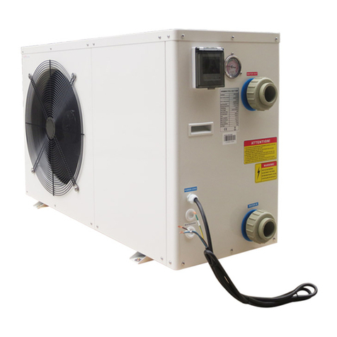
Ecoplus SWBC-19.5H-B-S Service manual

Installation & Instruction Manual
AIR SOURCE HEAT PUMP WATER HEATER
Model:
SWBC-13.5H-B
SWBC-19.5H-B-S
SWBC-24.0H-A-S

Ⅰ.To our customers(before installation)
Ⅱ.Product Introducing-----------------------------------------------------------------------2
Ⅲ.Work principle------------------------------------------------------------------------------3
Ⅳ.Performance Data--------------------------------------------------------------------------4
Ⅴ.Dimension------------------------------------------------------------------------------------5
Ⅵ.Operation introductions------------------------------------------------------------------7
Ⅶ.Wire Circuit Diagram--------------------------------------------------------------------11
Ⅷ.Installation instructions-----------------------------------------------------------------13
Ⅸ.Maint enance---- ----- ----- ----- ----- ---- -- ----- ---- -- ----- ------ ----- ----- ---- -- 17
-------------------------------------------------1
CONTENTS
Water heater
Contents

Dear Sir:
Ⅰ.To our customers Water heater
In order to use this machine safely, please read this INTRUCTION MANUAL carefully
before using and installation. Heat pump water heater is a professional machine, it may
cause damage or hazard when wrong installed, it should be installed by a competent
person in accordance with the relevant standards for the country of use.
WARNING:
ELECTRICAL POWER MUST BE SWITCHED OFF
BEFORE STARTING ANY WORK ON JUNCTION BOXES
1.Before installing the heat pump, please ensure that the electrical supply corresponds
to the specification indicated on the unit s rating label before proceeding with the
connection in accordance with the wiring diagram supplied. Please check carefully
on the rating label and the wiring diagrams that pasted on each heat pump unit.
2.The unit must be EARTHED to avoid any risks caused by insulation defects. It is
forbidden to start any work on the electrical components without switching off the
electrical supply to the unit. Electric leakage switch protection device MUST be
installed.
3.It is forbidden to start any work on the electrical components if water or high
humidity is present on the installation site.
4.When the unit is being connected, ensure that no impurities are introduced into the
pipe work and the water circuits.
5.All maintenance or repairmen of the heat pump must be performed by competent
technicians.
6.It could be hurtful when generated hot water reaches 52 ℃, please mix with cold
water before using.
7. To prevent any damage to the fan or any accidents, it is forbidden to put your
fingers or any other objects into the air outlet. Kids or children should be kept
away from the heat pump.
8. This appliance is not intended for use by persons (including children) with
reduced physical, sensory or mental capabilities, or lack of experience and
knowledge, unless they have been given supervision or instruction concerning
use of the appliance by a person responsible for their safety.
9.Children should be supervised to ensure that they do not play with the appliance.
1

Product Introducing
Safe and Reliable
Unlike traditional electric water heater, heat pump water heater do not directly generate
heat by electricity , it use less electricity to move heat from one place to another , electric
circuit is separated from water circuit ,which is also not easy for electric shock,
inflammable , explosion and poisoning ! Safer and more reliable!
Highly efficient & Energy saving
Heat pump water heater absorb plenty of heat from free ambient air, and can supply same
hot water volume as electric heater. Electricity consumption is only 1/4 compared to
electric heater, very energy saving!
Environmental Friendly
Heat pump not only use less electricity to get heat from ambient air , but are also able to
combine using with solar equipment , will not cause pollution and no poison gas
exhausting .
All Round The Year Hot Water
Heat pump water heaters are not affected by seasonal climate, provide hot water all year
round even in cloudy or rainy days!
Durable and long-lasting time
Heat pump spare parts such as compressor and 4-way-valve are made by famous brand
manufacturer , and casing panel is corrosion resistance, very durable and long-lasting
time .
Convenient Installation
Installation site for heat pump can be the roof, the garage , the kitchen, the storing room ,
the basement and so on, very convenient on installation .
Wide Application
Heat pump water heaters are applicable for family, factory, school, hotel , hospital , and
laundry ,etc. Wide application for different using request.
Ⅱ.Product Introducing Water heater
2

Work principle
The low temperature and low pressure refrigerant gas come from the evaporate to the compressor,
After the compressor compress it , the refrigerant gas became high temperature and high pressure.
Then the gas come into the water condensation into liquid, emit a lot of condensation heat,
condensing heat absorbed by water, making the water temperature increased, and then the liquid
refrigerant come through the expansion valve, with a fan , the evaporate heat in the air, after all
evaporation , the low pressure compressor refrigerant gas inhalation in the compressor, after
working through the compressor, a high temperature and high pressure of the refrigerant gas from
the compressor to exhaust emissions, such reciprocating cycle.
BK BL series
90℃左 右
Power supply Temp adjustor
90 Around℃
Heat water 60 ℃
Condenser
Tap water 18 ℃
Compressor
Gas and liquid
separated controller
Air energy supply
Evaporator
Liquid tank Dry filter Expand valve
BC series Power supply
Heat water
outlet
Water inlet
Compressor
Heat energy
pass to water
Dis c harg e
he a t equ i pment
Absorbing
air heat
energy
Ab so rbin g
heat eq uipmen t
Liquid tank Dry filter Expansion valve
Ⅲ.Work principle Water heater
3

Performance Data
Air source heat pump water heater sidewind series
3 8 0 V / 3 P H / 5 0 H Z
SWBC-13.5H-B
1 3 5 0 0
3.6
16.7
580
220V/1PH/50HZ
1
1
1
9 0
9 5 0
5 8
1 1 1 5 * 4 7 0 * 6 8 5
1 1 5
1 9 5 0 0
4 . 9
7 . 5 x3
8 3 8
SWBC-19.5H-B-S
55℃
60℃
1
1
2
9 0 x 2
9 5 0
6 2
1115*470*1250
1 4 7
24000
6.7
1 1 . 2 x3
1 0 2 0
SWBC-24.0H-A-S
1 . 2 5
1
1
250
850
5 9
810*780*960
160
Model
Rated heating capacity(w)
Power supply(V/Ph/Hz)
Input power(kw)
Running current(A)
Thermostat factory setting( )℃
Thermostat maximum setting( )℃
Water connections(mm)
Compressor quantity
Fan motor quantity
Fan motor input(w)
Fan speed( )RPM
Noise(dB(A))
Net dimension(mm)
Net weight(kg)
Circulating unit hot water generated(L/h)
Ⅳ.Performance Data Water heater
4
Measuring conditions: dry bulb 24 , wet bulb 19 , water inlet 40 , water outlet 60 .℃ ℃ ℃ ℃

SWBC-13.5H-B SWBC-19.5H-B-S SWBC-24.0H-A-S
B
ACD
E
H
G
F
A
B
C
D
E
F
G
H
Model
Size
Measure: mm
The dimension for air source heat pump water heater
Ⅴ.Dimension Water heater
5
780
780
1035
100
275
440
760
425
470
1115
685
310
59
SWBC-13.5H-B
440
760
425
470
1115
265
55
1250
SWBC-19.5H-B-S

The dimension for High efficiency tube in shell heat exchanger
Measure: mm
Measure: mm
Ⅴ.Dimension Water heater
Model
Size
388
310
H
H1
SWBC-13.5H-B
6
Model
Size SWBC-19.5H-B-S
SWBC-24.0H-A-S
350
265
310
220
H
H1

Ⅵ.Operation introductions Water heater
1) Controller introduction
ON/OFF MODE UP/DOWN
SET TIMER
1
2
Cooling mode
Set point temp
Heating mode
Tank outlet temp
Timer on
Timer off
Clock
Timer on/ off sign
First timer
Second timer
Press button to turn on or turn off the unit.
Press button to choose heating mode.
Long press this button for 3 seconds to enter parameter setting status inquiry.
S/N Content
0 Water inlet temp sensor
1 Ambient temp sensor
2 Coil temp sensor
3 Exhaust temp sensor
4 Gas suction temp sensor
5 Electrical expansion valve running status
6 Water outlet temp sensor
7 Reservation
8 Working mode
2) Wire Controller Operation
Range
0℃ ~ 85℃
-30℃~85℃
-30℃~85℃
50℃~120℃
-30℃~85℃
0℃ ~ 85℃
0℃ ~ 85℃
1 heating only
0 cooling & heating
7
Actual tested value

Ⅵ.Operation introductions Water heater
Press or to directly adjust the temperature.
Press button and button at the same time, can turn on/off electrical heating.
Press button and buttons for 3 seconds, force defrosting function is on.
Press button once, to enter clock setting.
When long press this button for 10 seconds, can check and adjust the parameters
along with up or down buttons.
Parameters reference table
Parameters
Heating set point temp
Cooling set point temp
Temp difference setting
Water outlet temp adjustable
Defrosting period
Temp to enter defrosting
Max defrosting time
Temp to exit defrosting
To exit auxiliary heating (ambient temp)
Maximum set point temp
High pressure switch
Low pressure switch
Flow switch
Target over-heat degree
Second set point (maximum setting)
Second set point (minimum setting)
System
Single phase/ 3 phase
S/N
0
1
2
3
4
5
6
7
8
9
a
b
C
D
E
F
Default
12
5
0
45min
-2
8min
15
12
60
1(yes)
1(yes)
1(yes)
5
50
30
50
Reserved
0: single phase (220v)
1: three phase (380v)
C
C
C
C
C
C
C
C
C
C
Range
8 -25
2 -15
0 - 10
20min-90min
-30 - 0
3min-15min
5 - 25
0 - 40
35 - 65
0-1
0-1
0-1
-5 - 15
40 - 50
20 - 30
0-1
0-1
20 -60
C
C
C
C
C
C
C
C
C
C
C
C
C
C
C
C
C
C
C
C
C
CC
Under stand by/start-up state, press button, when the place which shows hour is
flashing, press or to adjust the hour; press button again, when the place
which shows minute is flashing, press or to adjust the minute, then press
button again, confirm the time setting.
8

Ⅵ.Operation introductions Water heater
Setting about S1 & S2 switch
S1 Switch---Second set point
S2 Switch---Long distance demand for heating
Please refer to the wiring diagram for the location of above S1 & S2 switch.
1)Heat pump turns on when S2 switch has well connected.
While S2 has connected, suddenly press the off button on the LCD controller.
Heat pump will stop for 3 minutes. However, heat pump continues to turn on if S2
still has been connected after 3 minutes.
2)The Timer function is out of validity either S2 switch has connected.
3)Heat pump turns off when S2 switch is disconnected. Meanwhile, need to
use LCD controller to turn on /off the heat pump.
4)Second set point available when S1 switch has well connected.
At the same time, water temp set point setting decided by ambient temp, Parameter
C and Parameter D. (Both C & D parameter could be adjusted).
Parameter C (maximum setting range 40-50 °C , default 50°C )
Parameter D (minimum setting range 20-30°C, default 30°C )
A. When ambient temp < 5°C, set point temp refer to the data of Parameter C.
B. When ambient temp >15°C, set point temp refer to the data of Parameter D.
C When < ambient temp < 15°C, set point temp = Data of Parameter C-(Data of
parameter C- data of parameter D)/ (15-5)*(ambient temp -5).
For example, when ambient temp is 18 deg c, Parameter C is 50 deg c, Parameter
D is 30 deg c.Then set point temp=50-(50-30)/(15-5)*(18-5)
5)When S1 disconnected, set point temp control by LCD controller.
(Refer to the setting of Parameter C & D (default setting 50° C & 30°C )
Press to enter the setting of timer on and timer off (Totally you may set 2 difference
timers on and timer off.)
flashed, press or to adjust the hour; press button again,shows minute data
and“ON”“1”flashed,
press or to adjust the minute; press button again shows hour data and“OFF”
“1”flashed, press or to adjust the hour; press again shows minute data
and “OFF”“1”flashed, press or to adjust the minute; Press again, then
the timer on and off time setting is finished. If you want to cancel this setting,press
then it will be cancelled.
Under the stand by/start-up state, press button shows hour data and“ON”“1”
At the stand by/start-up state, long press button 3 seconds,shows hour data and
“ON”“2”flashed, press or to adjust the hour; press button again,
shows minute data and“ON”“2”flashed,press or to adjust the minute;
press button again shows hour data and“OFF”“2”flashed, press or to
adjust the hour; press again shows minute data and “OFF”“2”flashed, press
or to adjust the minute; Press again, then time on and time off time setting is
finished. If you want to cancel this setting, press then it will be cancelled.
Important Note: During your setting of 2 timers(at one time) , all timer on/off setting
time (00:00) shall NOT be same.
9

Ⅵ.Operation introductions Water heater
3) Malfunction data
Malfunctions
Communication failure
Water tank sensor failure
Ambient temp sensor failure
Coil temp sensor failure
Exhaust temp sensor failure
Gas suction temp sensor failure
Water inlet temp sensor failure
Water flow switch protection
High pressure protection ( 3 times within 1 hour)
Low pressure protection ( 3times within 1 hour)
Exhaust temp too high protection
High pressure protection
Low pressure protection
Anti-Freezing protection
Phase order failure
S/N
1
2
3
4
5
6
7
8
9
10
11
12
13
14
15
Code
E10
P6
P5
P3
P4
P9
P2
E3
E1
E2
P8
E4
E5
P7
E9
Solution
Turn on for heating
10

Wire Circuit Diagram
Water heater
Applicable model: SWBC-13.5H-B
11
Applicable model: SWBC-19.5H-B-S
Electronic
Expansion
Valve
Wire
Controller
HP-SW
LP-SW
FLOW-SW
TO AC CONTACTOR
OF E-HEATER
TO AC CONTACTOR
OF WATER PUMP
FROM POWER
Compressor
AC contactor
FAN MOTOR
N-LINKER
COM-LINKER
4-WAY
FM1
Cn5
CN1 CN3 CN2
4
5
CN4
IN1
IN2
IN3
IN4
IN5
IN6
IN7
COM
CM
R
C B A N
R
S
T
N
1
3
5
A1
2
2
6
A2
S
T
FM2
Transformer
T1
TH1 TH2 TH3 TH4 TH5 TH6 TH7
T2
2 2 2222
T3 T4 T5 T6
Coil temp sensor
Ambient temp sensor
Tank temp sensor
T2
T3
T1
Suction temp sensor
Water inlet temp sensor
Exhaust temp sensor
T6
T4
T5
S1 Second set point
S2 Long distance demand for heating
S1
7
6
5
4
3
2
1S2
AIR SOURCE HEAT PUMP WIRING DIAGRAM
OUT1 OUT2 OUT3 OUT4 OUT5 OUT6 OUT7 OUT8 OUT9
Ⅶ.Wire Circuit Diagram
AIR SOURCE HEAT PUMP WIRING DIAGRAM
S
CM
TO POWER SUPPLY
C
CONTACTOR 1
KM-6
CON
N
START
COMP-R
COMPRESSOR
R
Y/G
L N
15K 2W
N
Electronic
Expansion
Valve
Wire
Controller
HP-SW
LP-SW
FLOW-SW
TO AC CONTACTOR
OF E-HEATER
TO AC CONTACTOR
OF WATER PUMP
FAN MOTOR
N-LINKER
COM-LINKER
4-WAY
FM1
Cn5
CN1 CN3 CN2
4
5
CN4
IN1
IN2
IN3
IN4
IN5
IN6
IN7
COM
C B A N
Transformer T1
TH1 TH2 TH3 TH4 TH5 TH6 TH7
T2
2 2 2222
T3 T4 T5 T6
Coil temp sensor
Ambient temp sensor
Tank temp sensor
T2
T3
T1
Suction temp sensor
Water inlet temp sensor
Exhaust temp sensor
T6
T4
T5
S1 Second set point
S2 Long distance demand for heating
S1
7
6
5
4
3
2
1S2
OUT1 OUT2 OUT3 OUT4 OUT5 OUT6 OUT7 OUT8 OUT9

Wire Circuit Diagram
Ⅶ.Wire Circuit Diagram Water heater
Applicable model: SWBC-24.0H-A-S
12
Electronic
Expansion Valve
T1 T2 T3 T4 T5 T6
Coil temp sensor
Ambient temp sensor
Tank temp sensor
T2
T3
T1
Suction temp sensor
Water inlet temp sensor
Exhaust temp sensor
T6
T4
T5
S1 Second set point
S2 Long distance demand for heating
AIR SOURCE HEAT PUMP WIRING DIAGRAM
GND
R S T N
COMP
GND
C B A
CN5
CN1 Cn2 CN3
Cn4
NOUT1 OUT2 OUT3 OUT4 OUT5 OUT6 OUT7 OUT8 OUT9
1 3 5
2 4 6
A1 A2
T1 L1
A1 A2
22
Transformer
2
22 22 22 22 22 22 4
5
TH1 TH2 TH3 TH4 TH5 TH6 TH7
COM
IN7
IN6
IN5
IN4
IN3
IN2
IN1
AC380V/50Hz
High Press
Switch
Low Press
Switch
FM
To AC
connecter
of water
pump.
To AC
connecter
of water
tank
electric
heating
1 2 3 4 5 6 7 8 9 10 11 12 13 14 15
Water flow
S1
S2
Wire
Controller
4-WAY

Installation instructions
1. Unit installation
1).Installation location
Host unit
1Should be installed in a larger & well-ventilated place.
1Installation location should ensure unhindered access outlet (inlet & outlet shown as
below).
1Install gutter or set up positions near the outfall, to facilitate the drainage.
1The installation base or bracket should be steady, to ensure the smooth operation of
running units.
1Make sure the unit is vertical after installation, and no incline.
1Make sure not to install the host unit in the any conditioner of pollution, corrosive gases,
sun and fallen leaves, etc.
1Installation location must not next to place of incendive , easy-explosion and fire .
1Installation must pay attention to the distance between the barriers shown in below
picture (pay attention to arrow direction).
Water tank
1Water tanks should be placed where ambient temperature is above 0℃ .
1Can be installed outdoors or the top of the building (based on the size of water tanks and
the load-bearing capacity of the building and so on).
1Do not install water tanks in the pollution, corrosive gases place.
2).Unit installation
1Units base can be installed as cement concrete structures, steel brackets can also be used,
add the shockproof rubber pads , make the base surface flat.
1Units can be designed based on the working performance.
(See Table of technical performance parameters)
1Unit should have drain or drainage inlets.
1Normally required to install in the place where setted cement concrete base.
Above 1000mm
2000mm above the top
Air inlet
Air outlet
Heat pump
Air inlet
Above 1000mm
1000mm above the top
Above 1000mm Above 1000mm
Above 1000mm
Air inlet
Air inlet Air inlet
Ⅷ.Installation instructions Water heater
13

Installation instructions
2. Pipeline connecting
Installation notes:
1Water drain pipes, overflow pipes should be installed next to the drainage inlets to
facilitate drainage, vent valve should be installed on vent pipes.
1Repair valve should be installed in front of the electromagnetic valve on the pipeline
system, which is convenient for future repair.
1User water pressure should less than 0. 6 Mpa.
1All pipelines should choose metal pipe (such as stainless steel, with Lining Plastic and
lining stainless steel and thin-walled copper pipe or, etc.). The use of plastic pipe
(such as the PP-R, ABS, etc.) should consider the pipeline expansion between the host
unit and water tanks .
1Water supply and pause valves may need to keep warm in the winter (according to the
local winter temperature) to avoid the broken of water supply and pause valve.
Water system installation
1All the pipeline tubing should be matched as shown on the manual, and in accordance
with national corresponding construction standards.
1Installation of water pipes should be straight and flat, pipeline collocation should be
rational, ensure to minimize bending; reduce the resistance loss of the water system.
1Pipeline and connecting parts are not allowed a leakage phenomenon.
1After the installation of circulating pipe between tap water pipes, host unit and water
tanks ,should carry out water leakage testing, and eject the sewage to ensure the sy
stem's cleanness.
1If no water leakage, keep the hot water pipe warm.
3. Project example:
Application of heat pump water heater engineering systems have different forms. Here
are two kinds of stand-alone group water heating system, only for your reference.
Cycling
pump
Stainless steel soft pipe
Discharge pipe
Discharge pipe
Cold water supply
induction valve:D1
Water tank
High water level
Low water level
Constant temp pump
Timing water supply system wiring
6
5
4
3
2
1
Water flow meter
Number
Sign valve
Inducting valve
pause valve
Y type filter
water pump
Name Design
Ⅷ.Installation instructions Water heater
14

Installation instructions
Running Test and operation
1. Preparatory work before the running test.
a) Inspection of heat pump water heater units:
1Check if the unit appearance and the pipeline system were damaged during transport.
1Check if there is air exist in the water pipes, if yes, should empty all the air inside by the
manual exhaust valve and the exhaust valve on the water pumps.
1Check if the fan rotor interference the fan fixing board and fan protection net.
b) Check the electricity distribution System
1Check if the power supply same as shown on manual and rating label.
1Check if all the power supply and control wiring are all well connected, check if the wiring
is connected as wiring diagram and reliability of earth wiring.
c) Check Pipeline system
1Check the pipeline system, make sure the water supply pipes, water return pipes, pressure
gauges, thermometers, valves, water flow switch are safe and correct.
1Check if having opened all the valves that should be opened, and having closed all valves
that should be closed.
1Check if all necessary attemperators are good.
Cycling pump
(Inside)
Extra electric
thermal controller
Constant Temp Controller
Discharge pipe D 1
Constant Temp
Controller
45℃
50℃
55℃
Water Tank
High water level
200
User
Instant water supply system wiring
Low water level
8
7
6
5
4
3
2
1
Single valve
Design
Constant temp controller
water flow meter
temp sensing controller
inducting valve
pause valve
Y type filter
water pump
Name
Number
Ⅷ.Installation instructions Water heater
15

Running Test and operation
2.Running test
This running test must be performed by professional staff!
1 Overall test can be run if the entire system inspection is conformed to regulations.
1 Connected to power, start the heat pump, host unit delays three minutes then auto-start.
For three-phase power supply unit, first check whether the fans and pumps' rotary
direction correct or not, if not, immediately shut down the power and adjust phase
sequence. Measure the compressor operation current, and if any abnormal noise.
Check whether the unit conform to the requirements, run for a period of time
(general 3 days),after that, the unit can be used normally.
3.Normal operation
1 Heating process: start - up - water pumps runs -water flow switch inspection --- Fan
operation compressor operation (when the low water level cut off, water supply
induction valve opens
1 Operation Control:
1 Water level control:When the low level switch disconnect, open the water supply
induction valve to supply enough water, meanwhile stop the water supply pump.
Open the water supply pump when high level switch closed, After high-level switch
closed for two minutes , open water supply induction valve ( at least 2 minutes).
1 When water pump is on and the high level switch cut off ,if water temperature <(set
Temperature -5 degrees) , shut down water supply for tanks, If water tank temperature
> (temperature -2 degrees) then open the water supply induction valve , after high-
level switch closed for two minutes stop the water supply induction valve.When
water pumps stopped, whatever conditions , should supply enough water. (Water
supply switch on at 2 minutes).
1 For the first power-on boot, the circulating water pump, compressor, fan motor runs
after low level switch closed.
1 During the unit operation, circulating pump open.When the unit stopped, the
circulating pump will be delayed 30 seconds then stop functioning.
1 When water pumps open, meanwhile open water return induction valve, 10 minutes
later, test the return water temperature, when the return water temperature > (water
temperature -5 degrees), the return water induction valve stops. If the return water
temperature <(tank water temperature -10 degrees), open the water return valve so
that the water supply pump constantly store the hot water.When water supply pump
closed, shut down the water return valve at the same time.
1 For normal start-up, the 4-way valve cut off, only when defrosting ,the unit will work
in normal.
O N
Water temperature
(Set water
temperature-5)
O F F
Set water
temperature
Ⅷ.Installation instructions Water heater
16

Maintenance
Heat pump water heater is a high automatic equipment, please perform regular inspection
termly. If the unit can be long-term and efficiently maintenance, the operating reliability
and service life will have an unexpected increase.
1.The extra water filters should be cleaned regularly to ensure clean water quality of the
system, and to avoid damage caused by dirty water filter blocking.
2.Users should pay attention for usage and maintenance to below : all units' protection
devices are set up before leaving factory, do not make any adjustment by yourself.
3.Frequently check the power supply and electrical wiring system is solid or not, whether
electrical components are abnormally working, if yes, should timely maintenance and
change for a new one.
4.Perform regular checks of the water supply system, check whether the tank safety valve,
liquid level controller and exhaust devices work properly, so as to avoid air into the system,
and reduce the water cycle volume, thus affect the heating function and operation reliability.
5.Check whether pumps and water valves are normal working or not, whether water tubing
and water pipes connector are leakage or not.
6.The unit and around should remain clean, well-ventilated. Regularly clean (1-2 month)the
side air heat exchanger to maintain a good effect of heat exchange.
7.Frequently check whether each part of the unit work normal or not, check whether there is
oil on the pipeline joints and charging valve to ensure that no refrigerant leakage.
8.Do not piling up debris around the unit, so as not to block from air inlet and outlet, the unit
around should be kept clean the dry, well-ventilated.
9.If the unit stops for a longer time, should drain all the water in the pipeline, cut off power
supply, and sets the protective equipment.When re-run the unit, complete inspection is a
must before reboot.
10.When unit failure, and the user can not resolve the problem, please call our Company in
local maintenance department, in order to promptly send people for maintenance.
11.Host condenser cleaning.We propose to use 50 -60 , and 15% hot phosphoric acid for
condenser cleaning, launch the circulating pump of the host unit for three hours' cleaning,
finally rinse with water three times. (Propose to back up a 3-way connector when installing
the pipeline, block one joint),in order to clear the connection pipe. Do not use corrosive
cleaning fluid for condenser cleaning.
12.Water tanks need to remove theWater scale after some time (normally two months,
according to the water quality of local place).
℃ ℃
Ⅸ.Maintenance Water heater
17

Air Source Heat Pump-Water Heater
This manual suits for next models
2
Table of contents
Other Ecoplus Heat Pump manuals
Popular Heat Pump manuals by other brands

Panasonic
Panasonic WH-MDC05F3E5 Service manual

Carrier
Carrier Infinity 25VNA4 installation instructions

Friedrich
Friedrich VRP12K Service and parts manual

Gree
Gree Versati II Series manual

Carrier
Carrier Gemini 38AU07 Series installation instructions

Pfannenberg
Pfannenberg DTX 8161 Operating and assembly instruction

York
York YLCA 40 user manual

Hitachi
Hitachi TAW-270NH2A Operation manual

Atlantic
Atlantic alfea S S5 Installation and operating manual

Rinnai
Rinnai EHPA315VMA Operation & installation manual

Dimplex
Dimplex System M Compact Plus C 6kW Installation and operating instruction

Nibe
Nibe SOLAR 40 Installer manual