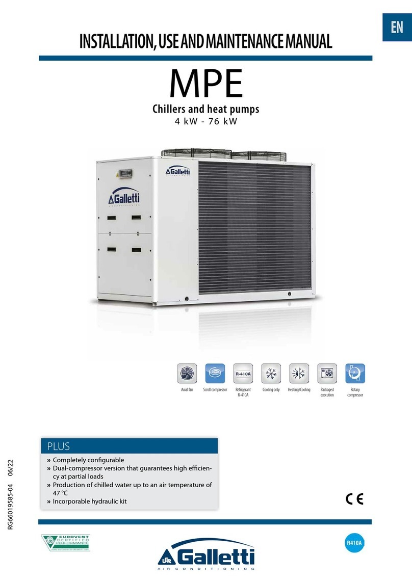
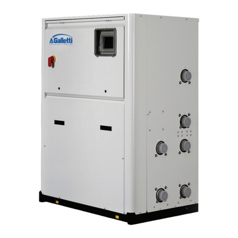
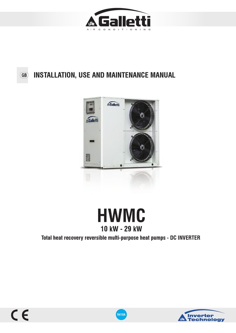
Galletti LEP Quick start guide

GB
Installation use and maintenance
LEP
Multifunction heat pumps
40 – 420 kW

Page 2 of 28
RG66007652– Rev.00

Page 3 of 28
RG66007652– Rev.00
CONTENTS
Page
1. GENERAL DESCRIPTION 6
1.1 The series 6
1.2 Structure 6
1.3 Field of application 6
1.4 Cooling circuit 7
2. PRELIMINARY PROCEDURES 12
2.1 Inspection upon reception 12
2.2 Lifting and conveyance 12
2.3 Unpacking 13
2.4 Positioning 13
3. INSTALLATION 13
3.1 Installation clearance requirements 13
3.2 General recommendations for hydraulic connections 14
3.3 Hydraulic connection to evaporator 14
3.4 Filling tank and/or pumps (if foreseen by the system) 16
4. ELECTRICAL CONNECTIONS 16
4.1 General Information 16
4.2 Electric connections of the circulation pump 17
4.3 Remote controls 17
4.4 Remote Summer-Winter changeover [Heat pump versions] 17
5. STARTING UP 17
5.1 Preliminary checks 17
5.2 Commissioning instructions for LEP series chillers 18
5.3 Starting operation 19
5.4 Checks during operation 19
5.5 Checking refrigerant load 19
5.6 Stopping the unit 20

Page 4 of 28
RG66007652– Rev.00
CONTENTS
Page
6. OPERATING LIMITS 20
6.1 Use of glycol solutions 21
6.2 Working limits 21
6.3 Water flow to evaporator 22
7. SETTING CONTROL DEVICES 22
7.1 General Information 22
7.2 Maximum pressure switch 23
7.3 Minimum pressure switch 23
7.4 Service thermostat function 23
7.5 Antifreeze thermostat function 23
7.6 Anti-recycle timer function 23
8. MAINTENANCE 24
8.1 Warnings 24
8.2 General Information 24
8.3 Repairing the cooling circuit 25
8.4 Tightness test 25
8.5 Emptying and drying of the cooling circuit 25
8.6 Restoring R410A refrigerant load 26
8.7 Environmental protection 26
9. TROUBLESHOOTING 27

LEP
Page 5 of 28
RG66007652– Rev.01
Declaration of conformity
The declaration of conformity is attached to each unit

LEP
Page 6 of 28
RG66007652– Rev.01
1. GENERAL DESCRIPTION
1.1 The Series
The LEP series of water-cooled water chillers consists in a range of models which meet all different
system requirements:
LEP C water chillers - cold water only - R410A refrigerant
LEP H chillers and water-to-water heat pump - R410A refrigerant
1.2 Structure
All of the LEP series units are constructed with a support base and panelling made of galvanised sheet
metal painted with black polyester epoxy powders oven-polymerised at 180°C. The unit has an exclusive
design enhancing the overall assembly with a smart outward appearance. Moreover the closed unit
makes the components inaccessible: this aspect together with the wide use of soundproof material inside
the compartment, optional for low-noise version, reduces the emitted sound output to exceptionally low
levels (Lp < 66 dB-A @1 metre). The hydraulic/chiller connections are envisioned at the top, to reduce the
technical space required for installation. All the panels are removable making the unit fully accessible
even though routine maintenance only needs accessing from the front.
1.3 Field of application
LEP units are intended for cooling-heating water and glycol solutions up to a maximum of 30% the
weight, in civil, industrial and technological air conditioning environments. For large buildings, air
conditioning can be implemented as the floors/zones are sold or rented, by installing a LEP unit for each
floor in a small size technical room, thus dividing the investment in time. The possibility of keeping the
evaporator on the inside allows you not to add glycol to the water in the system. It also makes it possible
for all the components requiring maintenance to be installed in an easily accessible space. The
advantages of these products are summarised in the following table:
Water-cooled versions LEP C-H
oLess space taken up in plan
oPossibility of using water without glycol in the utility circuit
oHigh COP [Coefficient of performance] of thermodynamic cycle
oNo noise on the outside
oLess charging with refrigerant.
oInnovative aesthetical features and full safety since units are completely closed
oPossibility of combining an external Dry Cooler when disposable water cannot be
used to cool the condenser
oHeat pump mode with chiller side cycle inversion
oPossibility of even heat pump versions using condensation control
The use of LEP C-H units is recommended within the functioning limits carried in this manual, or else the
warranty attached to the sales contract would cease.
Do not install the unit in environments with gas or flammable dusts.
1.4 Cooling circuit
The cooling circuit is fully implemented in the Factory exclusively using prime brand components and
procedures in compliance with Directive 97/23 for all the brazing operations. The units are made with
single and double cooling circuit, using exclusively prime International brand components.

LEP
Page 7 of 28
RG66007652– Rev.01
Compressors: only prime international brand Scroll compressors are used on the LEP units.
The Scroll compressor is the best solution today in terms of reliability and efficiency in the
range of power outputs up to 182 kW for each circuit and the best solution in terms of emitted
sound output. N.B.: Scroll compressors, just like all air-tight compressors, are classified as
pressure recipients in compliance with PED for that which regards the low pressure section to
which the PS indicated on the data plate refers.
Heat exchangers: only brazed plate heat exchangers are used, made of austenitic stainless
steel AISI 304 with AISI 304 L connections, featured by a reduced carbon content to simplify
brazing operations. The solution of the brazed plate heat exchanger represents the state-of-
the-art in terms of thermal exchange efficiency and allows a strong reduction of refrigerant
load compared to standard solutions. The high degree of turbulence induced by the internal
corrugation of the plates together with their perfect smoothing features, makes it difficult for
filth to deposit or for limestone to build up on the condenser side. N.B.: due to thermal
insulation, the data plate in compliance with 97/23 PED is not legible, but the serial number of
the heat exchanger and the declaration of conformity are detected during production and are
an integral part of the HiRef archive.
Chiller components:
oMolecular and alumina sieve filter dryer activated
oSight glass with humidity indicator. The key is directly on the sight glass.
oMechanical thermostatic valve + external equalisation and built-in MOP function
oElectric thermostatic valve with step motor and specific electronic driver for the
maximum efficiency of the cooling circuit and to optimise operating parameters.
oCycle inversion valve (only heat pumps)
oOne-way valves (only heat pump)
oHigh and low pressure switches
oSchrader valves for control, access and/or maintenance
oRefrigerant-side safety valve
Electrical control board: the electrical control board is implemented and wired in compliance
with the directives EEC 73/23 and EEC 89/336 and to related standards. The board can be
accessed through the small door after having activated the main switch. All the remote
controls are implemented with signals at 24 V, powered by an isolation transformer positioned
inside the control board. A T control kit composed of thermostat and auxiliary fan is available
on demand. The unit is rated IP 43. N.B.: the mechanical safety devices such as the high
pressure switch have characteristic direct intervention and any microprocessor control circuit
failure cannot affect its efficiency in compliance with 97/23 PED.
Control microprocessor: the microprocessor on-board the unit controls the various operating
parameters by means of a keyboard set-up on the electrical control board:
oCompressor connection/disconnection to maintain the set-point of the chiller inlet
water T;
oAlarm management
High/ low pressure
Antifreeze
Flow switch
Pump alarm
oAlarm signals
oDisplay of operation parameters
oAntifreeze protection of evaporator
oControl of maximum number of compressor starts
oSerial output control (optional) RS232, RS485
oIncorrect sequence phases [not viewed on µP, but keeps compressor from starting]
[ref. Microprocessor control manual for further details]

LEP
Page 8 of 28
RG66007652– Rev.01
STANDARD COOLING CIRCUITS
Cooling only versions (NB: standard layout; refer to the layout attached to the unit)

LEP
Page 9 of 28
RG66007652– Rev.01

LEP
Page 10 of 28
RG66007652– Rev.01
Heat pump versions (NB: standard layout; refer to the layout attached to the unit)

LEP
Page 11 of 28
RG66007652– Rev.01

LEP
Page 12 of 28
RG66007652– Rev.01
2. PRELIMINARY PROCEDURES
2.1 Inspection upon reception
Upon receiving the unit, check that it is perfectly intact: the chiller left the factory in perfect conditions;
immediately report any signs of damage to the carrier and note them on the Delivery Slip before signing
it.
HiRef or its Agent must be promptly notified of the entity of the damage.
The Customer must submit a written report describing every significant sign of damage.
2.2 Lifting and conveyance
While the unit is being unloaded and positioned, utmost care must be taken to avoid abrupt or violent
movements. The unit must be handled carefully and gently. Avoid using machine components as
anchorages when lifting or moving it.
The unit should be lifted using Ø1½” GAS steel pipes at least 3mm thick, to be inserted in the holes
provided on the base side members (see fig. below) and identified by means of stickers. The pipes,
which should protrude by at least 300mm on every side, must be slung with ropes of equal length
secured to the lifting hook (provide stops at the ends of the pipes to prevent the ropes from slipping off
due to the weight).
Use ropes or belts long enough to extend beyond the height of the unit and place spacer bars and
boards on the top of the unit to avoid damaging the sides and top of the unit itself.
Attention: In all lifting operations make sure that the unit is securely anchored in order to
prevent accidental falls or overturning.

LEP
Page 13 of 28
RG66007652– Rev.01
2.3 Unpacking
The packaging must be carefully removed to avoid the risk of damaging the unit. The packaging includes
various materials: wood, cardboard, nylon, etc.
It is recommended to keep them separately and deliver them to suitable waste disposal or recycling
facilities in order to minimise their environmental impact.
2.4 Positioning
You should bear in mind the following aspects when choosing the best site for installing the unit and the
relative connections:
- size and origin of water pipes;
- location of power supply;
- accessibility for maintenance or repairs;
- solidity of the supporting surface;
All the models of the LEP series have been designed and built for indoor installations. Due to the special
care given to soundproofing and the fact that components and hot parts in general are closed inside, they
do not require special rooms.
We recommend placing a rigid rubber strip between the base frame and the supporting surface.
3. INSTALLATION
3.1 Installation clearance requirements
The hydraulic and cooling connections of units with remote condensers are on the top. This makes it
possible to position the unit practically against the rear wall. Only higher power sizes have hydraulic
connections on the back. It is however essential to ensure the following service clearance spaces:
- rear side: min. 0 metres (except for last 2 sizes)
- electric control board side: min. 1.0 metre to guarantee access for inspection and/or
maintenance of cooling components
- side: minimum 0.5 m for any special maintenance
- top side: min. 1.0 metres to correctly connect to external hydraulic and cooling piping.

LEP
Page 14 of 28
RG66007652– Rev.01
3.2 General recommendations for hydraulic connections
When you are getting ready to set up the water circuit for the evaporator you should follow the directions
below and in any case make sure you comply with national or local standards (use the diagrams
attached to this manual as your reference).
- Connect the pipes to the chiller using flexible couplings to prevent the transmission of vibrations and
to compensate for thermal expansions. Refer to the technical data table for the type and dimensions
of the hydraulic and chiller connections [only versions with remote condenser].
- Install the following components on the piping:
temperature and pressure indicators for routine maintenance and monitoring of the unit. Pressure
control on the water side allows to assess the correct functioning of the expansion tank and to detect
water leakage in advance.
sumps on inlet and outlet piping for temperature detection, for a direct view of operating
temperatures. They can also be consulted on the microprocessor on board the unit.
cut-off valves (gate valves) to isolate the unit from the hydraulic circuit for maintenance.
metal net filter (inlet piping) with mesh no larger than 1 mm, to protect heat exchanger from slag or
impurities inside the piping. This rule is especially important for commissioning.
air vent valve placed on the higher parts of the hydraulic circuit to bleed the air. [The internal pipes
of the unit are fitted with manual air vent valves for bleeding the unit itself: this operation may only
be carried out when the unit is disconnected from the power supply]
discharge cock and, where needed, drain tank in order to empty the system for maintenance or
seasonal stops.
3.3 Hydraulic connection to evaporator
The LEP series units have no internal water unit fitted, as it is fitted externally to the unit.
It is extremely important that the water inlet corresponds with the connection marked
with the writing “Water Inlet”.
Otherwise the evaporator would be exposed to the risk of freezing since the antifreeze thermostat would
not be able to perform its function; moreover the reverse cycle would not be activated in the cooling
mode, resulting in additional risks of malfunctioning This position does not enable consent by the water
flow control device.
The size and positions of the hydraulic connections are carried on the dimensional tables at the end of
the manual.
The water circuit must be set up in such a way as to guarantee that the rated flow rate of
the water supplied to the evaporator remains constant (+/- 15%) in all operating
conditions.

LEP
Page 15 of 28
RG66007652– Rev.01
The compressors work intermittently since the chilling demand of the utility does not generally coincide
with that supplied by the compressor. In systems containing little water, where the thermal inertia of the
water is lower, it is a good idea to check that the water content in the section delivering to users satisfies
the condition below:
NsSh
Cc
V
V = water content in user section [m3]
Sh = specific heat of the fluid [J/(kg/°C)]
= fluid density [kg/m3]
D= minimum time lapse between 2 compressor restarts [s]
DT = allowed water T differential [°C]
Cc = Chilling power [W]
Ns = No. of partialization steps
A standard feature of the LEP units is a device for controlling the flow rate (flow switch
for differential pressure switch) in the water circuit in the immediate vicinity of the
evaporator.
Any tampering with said device will immediately invalidate the warranty.
It is recommended to install a metal net filter on the water inlet piping.
Attention: During hydraulic connection operations, never work with open flames near or
inside the unit.
Ts
Tank
Q; TW in Q; TW out

LEP
Page 16 of 28
RG66007652– Rev.01
3.4 Filling tank and/or pumps (if foreseen by the system)
The tank has not generally been designed to withstand a depression greater than -0.15
Bar. For this reason, make sure the intake pressure of the pump, where the expansion
tank is positioned, is always be greater than 0.5 Bar while the pump is operating: this
helps to reduce the risk of cavitation.
It is extremely important that the installer follows and verifies the following procedure point by point in
order to prevent the risk of the tank exploding or pump cavitation.
a) Discharge the expansion tank until it reaches the pressure of 0.5 bar.
b) Fill the system and pressurise it until approximately + 1 Bar at pump intake (pump stopped).
c) Bleed the system.
d) Check the pump intake pressure (approximately 1 Bar) and start-up the system.
e) Stop the pump after 15-30 minutes and repeat the procedure from step c) until you can no longer
hear any noises caused by the presence of air in the system.
4. ELECTRICAL CONNECTIONS
4.1 General Information
Before carrying out any work on electrical parts, make sure the power supply is
disconnected.
Check that the mains electricity supply is compatible with the specifications (voltage, number of phases,
frequency) shown on the unit rating plate.
The power connection is made by means of a three-core cable plus "N" neutral point cable to power
single-phase loads (power supply with neutral optional).
The cross-section of the cable and line protections must conform to the specifications
provided in the wiring diagram.
The supply voltage may not undergo fluctuations exceeding ±5% and the unbalance between phases
must always be below 2%.
The above operating conditions must always be complied with: failure to ensure said
conditions will result in the immediate invalidation of the warranty.
The electrical connections must be made in accordance with the information shown in the wiring diagram
provided with the unit and current regulations.
An earth connection is mandatory. The installer must connect the earthing wire using the earthing
terminal situated on the electric control board (yellow and green wire).
The power supply to the control circuit is shunted from the power line through a transformer situated on
the electric control board.
The control circuit is protected by suitable fuses or automatic switches depending on the size of the unit.

LEP
Page 17 of 28
RG66007652– Rev.01
4.2 Electric connections of the circulation pump (if foreseen by the system)
All the units of the LEP series are provided with a voltage-free contact in the electrical control board with
which a low-voltage consent for the pump to start is powered.
Since it is an integral part of the supply, the pump must be started before the chiller and
stopped after the latter (minimum recommended start delay: 60 seconds). If connected
to the terminal in the electrical control board, this function is already performed by the
microprocessor on the unit.
4.3 Remote controls
If you wish to include a remote control for switching the unit on and off, you must remove the jumper
between the contacts indicated in the wiring diagram and connect the remote control to the terminals
themselves [see annexed wiring diagram] and then you must enable the "REMOTE" function with the
specific switch in the electrical control board.
4.4 Remote Summer-Winter changeover [Heat pump versions]
If you wish to include a remote summer/winter changeover for the unit, you must remove the jumper
between the contacts indicated in the wiring diagram and connect the remote control to the terminals
themselves [see annexed wiring diagram] and then you must enable the "REMOTE" function with the
specific switch in the electrical control board.
5. STARTING UP
5.1 Preliminary checks
-Check that the valves in the cooling circuit are open, if present.
-Check that the electrical connections have been made properly and that all the terminals are
securely tightened. This check should also be included in a periodic six-month inspection.
-Check that the voltage at the RST terminals is 400 V ± 5% and make sure the yellow indicator light
of the phase sequence relay is on. The phase sequence relay is positioned in the electrical control
board; if the sequence is not duly observed, it will not enable the machine to start.
-Make sure there are no refrigerant leaks that may have been caused by accidental impacts during
transport and/or installation.
-Check the power supply to the crankcase heating elements, where present.
The oil sump heating elements must be turned on at least 12 hours before the unit is
started. This function is carried out automatically when the main switch is off. Their
function is to raise the T of the oil in the sump and limit the quantity of refrigerant
dissolved in it.
To verify whether the heating elements are working properly, check the lower part of the compressors:
it should be warm or in any case at a temperature of 10 -15°C higher than the ambient temperature.

LEP
Page 18 of 28
RG66007652– Rev.01
The diagram above illustrates a specific property [Charles’ Law] of gases, which are more soluble in
liquids as the pressure increases but less soluble as the temperature increases: if the oil in the sump is
held at a constant pressure, an increase in temperature will significantly reduce the amount of refrigerant
dissolved in it, thus ensuring that the lubricating function desired is maintained.
- Check that the hydraulic connections have been properly made according to the indications given on
the plates located on the unit itself (proper inlet and outlet connections).
- Make sure that the water circuit is duly bled to completely eliminate the presence of air: fill the circuit
gradually and open the air vent valves on the top part, which the installer should have set in place.
5.2 Commissioning instructions for LEP series chillers
Hydraulic connections:
Attention: the machine is loaded with HFC R410A refrigerant – Group II EN 378 (non-hazardous
substances) and in compliance with that prescribed by the EEC regulation 2037/00.
Hydraulic connections must be carried out respecting the inlets and outlets as marked on the
connections. Pay special attention not to invert the condenser and evaporator circuits.
Provide cut-off valves on the water side to be able to intercept the unit respect to the
system and insert a net filter (which can be inspected) both on the evaporator side and on
the condenser side.
Load the hydraulic circuit making sure to bleed all the air inside of it.
Electrical connections:
Open the main switch, turn the locking screws of the electric panel ½-turn and open it.
Introduce the power cable 400/3/50+N through the hole provided on the left side of the unit and
secure it with a cable gland.
Connect the power supply and earthing wire to the terminals of the main switch.
Disconnect the “QF” circuit breaker of the compressor to prevent it from starting up in the wrong
direction in the event of an incorrect phase sequence.
Only for mCH2 control - Place the Local/remote selector button (SLR) in the centre at the top of
the electrical control board at LOCAL and power it by turning the main switch (IG) to ON.
Verify whether the phase sequence R-S-T is correct by checking the phase sequence relay
situated in the middle of the electric control board is lit green: if this does not occur, disconnect
the unit power supply from the external distribution panel and swap over two phases; then repeat
the operation. IN NO CASE SHOULD YOU TAMPER WITH THE WIRING DOWNSTREAM
FROM THE MAIN SWITCH since this may alter the correct sequence of other devices, e.g.
pump(s).
Rearm the “QF” compressor circuit breaker.
Close the electrical control board and lock it by means of the ½- turn locks.
Pressure
% R…. in oil
Oil T

LEP
Page 19 of 28
RG66007652– Rev.01
Starting up:
Check that all external cocks of the water circuit are open and water flows properly (the flow
alarm should not be triggered).
Put the main switch at the ON position.
oThe (external) pump will start immediately.
oAfter 60 seconds the compressor will start.
Check the water temperature differential (12-7°C to be detected by means of a thermometer on
the inlet and outlet water pipes of the unit).
Check that there are no leaks on the refrigerant side and water side.
Using all the screws supplied, close the unit.
Use:
consult the manual and the µChiller or pCO1 manual supplied with the unit for all maintenance
and/or set-up operations.
5.3 Starting operation
Before starting the chiller, turn the main switch off, select the desired operating mode from the control
panel and press the "ON" button on the control panel.
The unit will start up if enabled:
-by the safety devices of the water circulation pump/s
-by the flow switch (or differential pressure switch)
-by the T sensor measuring the temperature of the water returning from the system [chiller inlet]
-and no alarms have been triggered.
If the unit fails to start up, check whether the service thermostat has been set at the rated calibration
values.
You should not disconnect the unit from the power supply during periods when it is
inoperative but only when it is to be taken out of service for a prolonged period (e.g. at
the end of the season).
5.4 Checks during operation
- Check the phase sequence relay on the control board to verify whether the phases occur in the correct
sequence: if they do not, disconnect the unit from power supply and swap two phases of the three-core
cable at the unit input. Never attempt to modify internal electrical connections as any undue
modifications will render the warranty null and void.
- Check that the temperature of the water entering the evaporator is close to the service thermostat set
value.
5.5 Checking refrigerant load
- After a few hours of operation, check whether the liquid level indicator has a green crown: a yellow
colour indicates the presence of humidity in the circuit. In such a case the circuit must be dehumidified
by qualified personnel.

LEP
Page 20 of 28
RG66007652– Rev.01
- Large quantities of bubbles should not appear through the liquid level indicator. A constant passage of
numerous bubbles may indicate that the refrigerant level is low and needs to be topped up. It is allowed
for a few bubbles to be present especially in high-glide ternary mixtures such as HFC R410A.
-Also check that the end-of-evaporation temperature shown on the pressure gauge (refer to the
pressure gauge scale for the refrigerant R410A) is approximately 4 °C below the temperature of the
water leaving the evaporator.
- Make sure the superheating of the refrigerant fluid is limited to between 5 and 8 °C. To this end:
1) read the temperature indicated by a contact thermometer placed on the compressor intake pipe;
2) read the temperature indicated on the scale of a pressure gauge likewise connected to the intake
side; refer to the pressure gauge scale for the refrigerant R410A.
The degree of superheating is given by the difference between the temperatures thus determined.
- Make sure the subcooling of the refrigerant fluid is limited to between 3 and 5°C. To do this, you should:
1) read the temperature indicated by a contact thermometer placed on the condenser outlet pipe;
2) read the temperature indicated on the scale of a pressure gauge connected to the liquid inlet at the
condenser outlet; refer to the pressure gauge scale for the refrigerant R410A.
The degree of sub-cooling is given by the difference between the temperatures thus determined.
Attention: all the units of the LEP series are loaded with R410A refrigerant except for the
versions with remote condenser which are loaded with nitrogen. Eventual top-ups must
be done with the same type of refrigerant and are part of the routine maintenance
operations performed by qualified personnel.
Attention: the R410A refrigerant requires “POE” polyolester oil of the type and viscosity
indicated on the compressor data plate.
For no reason should a different type of oil be introduced into the oil circuit.
5.6 Stopping the unit
The unit can be stopped by pressing the "OFF" button on the front panel of the µP.
Attention: you should avoid stopping the unit using the main switch: the latter device
should be used to disconnect the unit from the electricity supply when there is no
passage of current, i.e. when the unit is already turned OFF.
Moreover, if you completely disconnect the unit from the electricity supply, the crankcase
heating elements, if included, will receive no power, thereby jeopardising the integrity of
the compressor the next time the unit is started.
6. OPERATING LIMITS
Functioning limits of LEP chillers regarding outlet water temperature from the unit and the temperature of
the condensing water: For applications with water T greater than the limits indicated, they must run with
R134a refrigerant (on demand). For relevant details contact the zone Agent.
Cooling only units
Water temperature
Minimum Maximum N.B.
Table of contents
Other Galletti Heat Pump manuals
Popular Heat Pump manuals by other brands

Centrometal
Centrometal Arctic Mono Series Technical manual

York
York AFFINITY YZH02411 Technical guide

Carrier
Carrier 38QW installation instructions

Samsung
Samsung AM CNBD Series installation manual

POOLEX
POOLEX Triline SELECTiON 150 Installation and user manual

Bosch
Bosch DOMESTIC HOT WATER HEAT PUMP Technical manual