EcoSmart Fire ESF.1.B.G28 User manual
WARNING
Improper installation, adjustment, alteration,
service, or maintenance can cause injury or
property damage. Read the installation and
maintenance instructions thoroughly before
installing or servicing this equipment.
DANGER
CARBON MONOXIDE HAZARD
This appliance can produce
carbon monoxide which has
no odor.
Using it in an enclosed space
can kill you.
Never use this appliance in
an enclosed space such as a
camper, tent, car or home.
WARNING
For outdoor use only
CAUTION
DO NOT DISCARD THIS MANUAL
•Importantoperatingandmaintenance
instructions included.
•Read,understand,andfollowthese
instructions for safe installation and operation.
DANGER
If you smell gas:
• Shutogastotheappliance.
• Extinguishanyopename.
• Ifodorcontinues,keepawayfromthe
appliance and immediately call your gas
supplierorredepartment.
WARNING
Do not store or use gasoline, or other
ammablevaporsandliquids,inthevicinity
of this or any other appliance.
An LP-cylinder not connected for use shall
not be stored in the vicinity of this or any
other appliance.
INSTALLATION,
OPERATION
AND MAINTENANCE
MANUAL
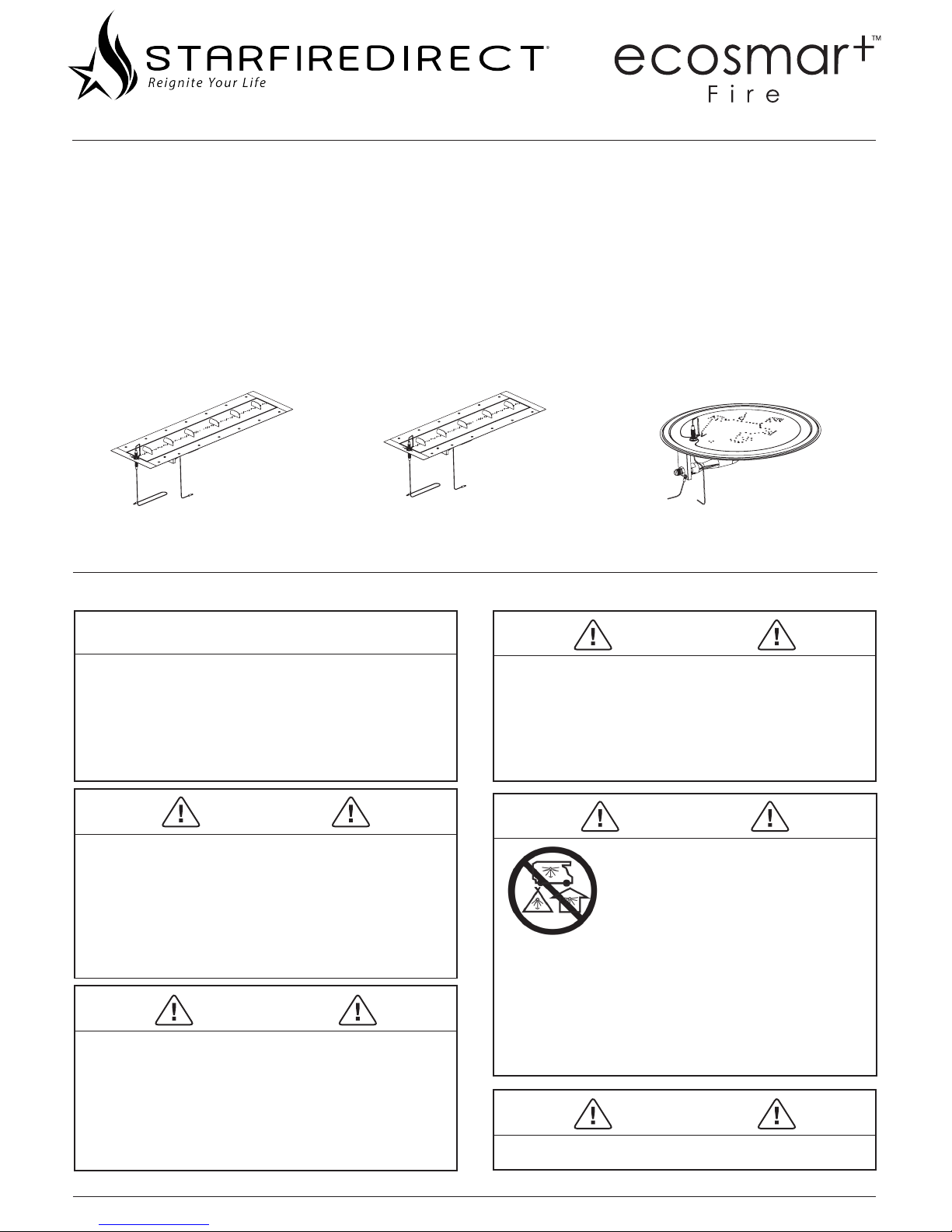
LONG GAS BURNER
ESF.1.B.G35 7.5lbs/16.5kg
MEDIUM GAS BURNER
ESF.1.B.G28 12.8lbs/5.8kg
ROUND GAS BURNER
ESF.1.B.G16 12.6lbs/5.7kg
ENGLISH
EDUCATE ALL USERS
Manuals can be found on our website or by contacting your local
distributor.
WHY REGISTER YOUR WARRANTY?
Registering your warranty achieves more than simply activating your
warranty - it provides our head oce with the information that we
require in order to communicate important safety and regulatory
information to you should the need arise.
This could include things like:
• Prompt notication in the unlikely event of a potential hazard,
• Reminders about regular safety steps and maintenance procedures,
• New model announcements or accessories that suit or enhance
your purchase.
It is important that we are able to communicate eectively with our
customers as part of our commitment to continual improvement,
consumer safety and property protection.
If you purchased your product through an external distributor, retailer
or agent. EcoSmart Inc does not have these details on le and may
have trouble sourcing them as systems and best practices vary from
business to business.
Please register your warranty today. You can do this online at
www.ecosmartre.com or by sending through your details as itemized
on Page 19 via email to info@ecosmartre.com.
EcoSmart Inc
3641 Holdrege Avenue, Suite B
LA 90016 USA
T + 1 (888) 590.3335
E usa@ecosmartre.com
LISTING AND CODE APPROVALS
A.ApplianceCertication
MODEL: ESF.1.B.G35, ESF.1.B.G28, ESF.1.B.G16
LABORATORY: Underwriters Laboratories, Inc. (UL)
TYPE: Decorative Gas-Fired Outdoor Fireplace
STANDARD: Outdoor Decorative Gas Appliances
ANSI Z21.97-2014
*CSA 2.41-2014
This appliance has been tested in accordance with ANSI Z21.97-2014
and CSA 2.41-2014 for Canada and has been listed by Underwriters
Laboratory (UL) for installation and operation as described in these
installation and operating instructions.
The installation must conform with local codes or, in the absence of
local codes, ANSI Z223.1 * NFPA 54 National fuel gas code – Natural
gas and propane installation code, CSA B149.1 – or propane storage
and handling code, CSA B149.2
The appliance, when installed, must be electrically grounded in
accordance with local codes or, in the absence of local codes, with
the National Electrical Code, ANSI/NFPA 70; or the Canadian Electrical
Code, CSA C22.1, if applicable.
B.BTUSpecications
Model
OriceSize Max Input BTU
LP NG LP NG
ESF.1.B.G35 #43 #31 55331 51706
ESF.1.B.G28 #43 #31 55331 51706
ESF.1.B.G16 #43 #31 55331 51706

© Copyright 2004 - 2016 EcoSmart Inc. All rights reserved. V251115
Contents
Markings
Important Safety Information
Clearances
Before You Start
Gas Hookup
Standard Equipment Received
Burner Assembly - Propane
Burner Assembly - Natural Gas
Lighting and Operating
Troubleshooting
Service and Maintenance
Reference Materials
3
4
5
6
7 - 8
9 - 10
11 - 12
13 - 14
15
16
17
18 - 19

ENGLISH
Markings
Listing Label Information/Location
Themodelinformationregardingyourspecicappliancecanbe
found on the rating plate attached to your burner via a metal chain.
Seethesampleratingplatebelowforlocationsofspecications.
This burner is for installation within approved
models ONLY and is not to be installed into
custom designs.
Model: EcoSmart Fire GB Series
ANSI Z21.97-2014 and CSA 2.41-2014 for Canada.
Installation must conform with local codes or in the
absence of local codes, ANSI Z223.1 * NFPA 54
National Fuel Gas Code – Natural gas and propane
installation code, CSA B149.1 – or propane storage
and handling code CSA B149.2
Type of Gas: Natural Gas, Propane Gas
WARNING: Must Not Be Used For Cooking.
WARNING: For Outdoor Use Only. If stored
indoors, detach and leave cylinder outdoors.
MINIMUM CLEARANCES: Top: 6 Ft. [72”] (1829mm)
Sides: 2 Ft. [24”] (610mm) Bottom: [8”] (203mm)
Minimum clearance from sides and back of unit to
adjacent combustible construction below top of unit
is 8” (203mm) from sides and 8” (203mm) from back.
Minimum horizontal clearance from sides and back
of unit to adjacent vertical combustible construction
extending above top of unit is 24” (610mm) from
sides and 24” (610mm) from back.
MFG. DATE XX/XX
SERIAL # XXXX DATE DE FAB. XX/XX
WARNING
Improper installation, adjustment, alteration,
service or maintenance can cause injury or
property damage. Refer to the owner’s information
manual provided with this appliance. For assistance
or additional information consult a qualied
installer, service agency or the gas supplier.
DECORATIVE
OUTDOOR GAS-FIRED
BURNER
EcoSmart Inc
3641 Holdrege Avenue
Suite B, Los Angeles
CA 90016 USA
42W4
Model
Orice Size Max Input BTU
LP NG LP NG
ESF.1.B.G35 #43 #31 55331 51706
ESF.1.B.G28 #43 #31 55331 51706
ESF.1.B.G16 #43 #31 55331 51706
WARNING!
If you do not follow these instructions exactly,
a re or explosion may result causing property
damage, personal injury, and/or loss of life.
A. This appliance must be lit manually. When lighting, follow
these instructions exactly.
B. Before lighting, smell around the appliance area for gas.
Be sure to smell next to the base of the appliance because
some gas is heavier than air and will settle on the oor.
WHAT TO DO IF YOU SMELL GAS:
• Do not try to light any appliance.
• Do not touch any electric switch. Do not use any phone in
your building.
• Immediately call your gas supplier from a neighbor’s
phone. Follow the gas supplier’s instructions.
• If you cannot reach your gas supplier, call the re department.
C. Use only your hand to turn the gas control knob or valve.
Never use tools . If the valve will not turn by hand, don’t
try to repair it. Call a qualied service technician. Force or
attempted repair may result in a re or explosion.
D. Do not use the appliance if any part has been underwater.
Immediately call a qualied service technician to inspect the
appliance and replace any part which has been underwater.
CAUTION: The gas pressure regulator provided with this
appliance must be used. This regulator is set for an outlet
pressure of 10.5 inches water column.
WARNING
Do not store or use gasoline or other ammable
vapors and liquids in the vicinity of this or any
other appliance. An LP-cylinder not connected
for use shall not be stored in the vicinity of this
or any other appliance.
LIGHTING INSTRUCTIONS
1. Depress sparker button and verify a spark is being produced
between the electrode tip and receiving probe.
2. Ensure control panel valve is in the “OFF” position and
slowly open valve on propane tank. If using natural gas or
whole-house LP, open ball valve. If not using a control valve,
skip this procedure until step 3.
3. Depress sparker button and continue holding button while
turning control valve to the on position. Release button once
ame is present.
TO TURN OFF GAS TO APPLIANCE
Turn the ON/OFF valve to “OFF” position at appliance for
a natural gas appliance For an LP appliance, turn the ON/
OFF valve to “OFF” at the appliance, then with a Type I or II
connection, turn the valve at the LP cylinder clockwise to the
“OFF” Position when the appliance is not in use.
FOR YOUR SAFETY,
READ BEFORE LIGHTING
BURNER
EcoSmart Inc
3641 Holdrege Avenue
Suite B, Los Angeles
CA 90016 USA

© Copyright 2004 - 2016 EcoSmart Inc. All rights reserved. V251115
Important Safety Information
Congratulations on your purchase of this decorative gas
appliance. The appliance you have selected is designed to provide
safeoperation,reliabilityandeciency.
This manual contains instructions for the safe installation and
use of your new gas appliance. Before installing and using this
appliance, read the entire manual and follow the instructions and
warnings carefully.
This owner’s manual should be retained for future reference.
If you are the installer (and not the owner) please ensure that
this manual is given to the owner for them to learn about safe
operation of the appliance and for future reference.
This appliance is a Decorative Gas Appliance for OUTDOOR USE
ONLY and MUST NOT be used for cooking. Do not burn solid fuels
in this appliance.
This gas burner is for installation within approved models ONLY
and is not to be installed into custom designs.
The information contained in this owner’s manual, unless noted
otherwise, applies to all models and gas control systems.
WARNING
If the information in these instructions is not followed
exactly,areorexplosionmayresultcausingproperty
damage, personal injury, or loss of life.
WARNING
Improper installation, adjustment, alteration, service, or
maintenance can cause injury or property damage. Read the
installation and maintenance instructions thoroughly before
installing or servicing this equipment.
WARNING
It is imperative the burner be kept clean
WARNING
Do NOT use this appliance if any part of it has been underwater.
Immediatelycallaqualiedservicetechnicianinspectthe
appliance and replace any part of the control system and any
gas control which has been underwater.
Installation and service of this appliance should be
performed by qualied personnel. We recommend
NFI certied, factory-professionals, or technicians
supervised by an NFI certied professional.
1. EXPLOSION/FIRE HAZARD
i. Do not operate in an area with oxygen tanks in use or if
ammablevaporsarepresent.
ii. Never smoke while lighting the appliance.
2. LOCATING THE FIRE
i. Keep children away from the
appliance
. Never leave children
unsupervisedwhenthereisoperating.
ii. In case of emergency, have on hand a multi purpose dry
chemicaltypereextinguisher(ABCinUSA).
iii. The customer warrants to EcoSmart Inc that after delivery of their
Fire, and while EcoSmart Inc retains any interest in the goods or
consigned goods (as the case may be), the customer shall comply
with all applicable acts, regulations and laws dealing with the
transport, unloading and storage of dangerous goods.
3. OPERATING THE FIRE
i. Do not use if damaged or malfunctioning.
ii. For decorative purposes only. Not suitable for continuous
operation. Do not use the
appliance
to heat or boil water or as
a cooking appliance. Do not put wood, charcoal, paper or other
combustible objects in the Fire.
iii. EcoSmart Inc is not liable for any damage caused by using the
incorrect type of fuel.
vi. NEVERleaveareunattended.
4. HOT SURFACE HAZARD
i. Due to high surface temperatures, keep children, pets, clothing
and furniture away from the unit for up to 1 hour of use, as the
unit is hot while in operation, contact with the
appliance
may
cause skin burns.
5. USING ACCESSORIES
i. Use only authorised decorative media with your
appliance
.
ii. Toreducetheriskofreorinjury,donotmodifythe
appliance
in any way.
iii. The Burner has not not been tested with an unvented gas
logset.Toreducetheriskofreorinjury,donotinstallan
unvented gas log set into this appliance.
For decorative media you must:
- Ensure the decorative media does not interfere with the
burner parts.
- Conrmqualityandsuitabilitytoensurethemediawillnot
explode, emit carbon monoxide or fumes when exposed to
extreme temperature variations.
- Fire accessories must not be smaller than
1
/
2
in (12.7mm) diameter
so that the accessories cannot impede the burner parts.
iv. Do notusettingsorspareparts,otherthanthoseavailable
from or recommended by the manufacturer of this appliance.
If you have any questions regarding any of the above important
safety information please contact your retailer or EcoSmart Inc.
Please store these warnings in a safe place for future reference.
ENGLISH
Clearances
When planning an appliance installation, it’s necessary to determine
the following information rst:
Environmental Conditions
WARNING:Ensurethatyourreispositionedawayfromammable
materials and other sources of ignition (combustible materials,
gasolineandotherammablevaporsandliquids)atalltimes.Pay
verycloseattentiontopositioningthereawayfromitemsthatmay
move as a result of wind and drafts.
For example trees/branches/
curtains/paper and the like.
The base of the burner within the model must never come into direct
contact with ammable materials.
Locating your appliance
Position the appliance adjacent to the gas supply line or LP gas
supply cylinder.
DO NOT locate the appliance where it will get excessively wet or
submerged in water.
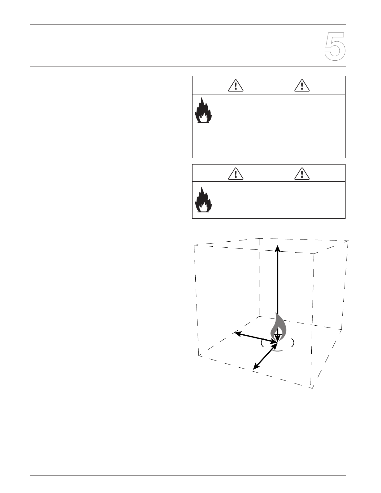
Minimum Clearances
Side clearances to xed and stable furniture items that are not
susceptible to movement such as lounges or patio furniture must remain
a minimum of 24in (610mm) away from the ame at all times.
Overhead clearances to items that are susceptible to movement
(e.g. Curtains/Trees) must remain a minimum of:
- 78.7in (2000mm) away from the ame at all times.
Ceiling clearances must remain a minimum of:
- 72in (1,829mm) to overhang from top of burner.
Please note that:
Any furniture items or ttings directly above or beside the Burner
installation must be deemed suitable for heat tolerances by
their manufacturer e.g. electronic items including screens and
entertainment equipment, wallpaper, laminates, veneers, glues and
reconstituted materials.
EcoSmart Inc is not liable for any injuries or damages sustained
through any installation not in compliance with this manual.
Areextinguisherisstronglyrecommended.
WARNING
EcoSmart Inc disclaims any responsibility for, and the
warranty will be voided by, the following actions:
• Installation and use of any damaged components.
• Modication of the burner assembly or burner orice.
• Installation other than as instructed in this manual.
Anysuchactionmaycausearehazard
WARNING
Fire Risk
Provide adequate clearance:
• Around air openings
• For service access
Locate appliance away from trac areas
72in MIN
(1,829mm)
24in MIN
(610mm)
24in MIN
(610mm)
© Copyright 2004 - 2016 EcoSmart Inc. All rights reserved. V251115
Before You Start
Tools and Supplies
Before beginning the installation, be sure that the following tools and
supplies are at hand:
• Gloves
• Safety Glasses
• Phillips screwdriver
• Non-corrosive leak-check solution
• Adjustable Wrenches
• 1 AAA battery
Initial Safety Inspections
Before assembling the appliance it is important to inspect the following
and determine if it is safe to proceed:
• Carefully remove all burner components from packaging.
• Check for damage. Do not use damaged components.
• The hose assembly must be replaced prior to the appliance being put
into operation if there is evidence of excessive abrasion or wear, or if
the hose is damaged. Do not use parts other than those specied by
the manufacturer.
• The burner must be replaced prior to the appliance being put into
operation if it is evident that the burner is damaged. Do not use parts
other than those specied by the manufacturer.
• Position the assembly in the desired location. This location must be
adjacent to the gas supply line. You must have easy access to the gas
valve control knob after it is installed and connected to the gas supply
because the ON/OFF gas valve is used to turn the burner on and o.
The location for the installation must be out of the pathways where
people may trip over it or in areas where the hose may be subject to
accidental damage.
In addition, for LP Gas Models:
• Be certain to mount or set the LP gas cylinder on a at stable
surface and restrain it to prevent it from tipping.
• Make sure the tank valve is turned completely o (clockwise).
• Ensure the tank valve has the proper external mating
threads (tank valve marked “USE WITH TYPE 1”).
• Inspect the hose shipped with the appliance for any
damage. Do not use if there is evidence of damage.
• Onceassembled,positionthehose out of pathways where people
might trip over it or in areas where the hose might be subject to
accidental damage.
WARNING
Asphyxiation Risk
• This gas appliance is for outdoor use in a well-ventilated space.
• This unit must not be installed inside an enclosed structure or
unvented appliance
CAUTION
Sharp Edges
Wear protective gloves and safety glasses during installation.
WARNING
Inspect appliance and components for damage. Damaged parts
may impair safe operation.
• Do NOT install damaged, incomplete, or substitute components.
Report damaged parts to your dealer.
ENGLISH
Gas Hookup
Fuel
Before making gas connections, ensure the appliance being installed is
compatible with the available gas type.
Gas Pressure
Proper input pressures are required for optimum performance. Gas line
sizing requirements need to be made following NFPA54.
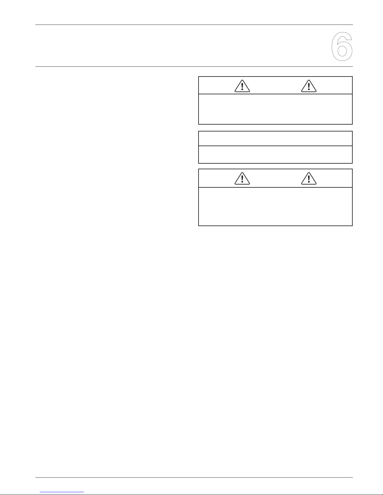
WARNING
Fire Risk
Explosion Risk
Verify inlet pressures.
• High pressure may cause overre condition.
• Low pressure may cause explosion.
• Verify minimum pressures when other household gas
appliances are operating
Install regulator upstream of valve if line pressure is
greater than ½ PSI.
Pressure requirements for appliance are shown in table below. Minimum
pressures must be met when other household gas appliances are
operating.
Manifold Pressure Natural Gas Propane
Minimum Inlet Pressure 7 in w.c 11 in w.c
Maximum Inlet Pressure 10.5 in w.c 14 in w.c
The appliance and its individual shuto valve must be disconnected
from the gas supply piping system during any pressures in excess of
1/2 psi (3.5 kPa).
The appliance must be isolated from the gas supply piping system by
closing its individual manual shuto valve during any pressure testing
of the gas supply piping system at test pressures equal to or less than
1/2 psi (3.5 kPa).
Gas Connection
Note: Have the gas supply installed in accordance with local building
codes, if any. If not, follow ANSI 223.1. Installation should be done
by a qualied installer approved and/or licensed as required by the
locality.(In the Commonwealth of Massachusetts installation must be
performed by a licensed plumber or gas tter.
Note: A listed (and Commonwealth of Massachusetts approved)
3/8 in (9.5mm). T-handle manual shut-o valve and exible gas
connector are connected to the 3/8 in (9.5mm) control valve inlet.
If substituting for these components, please consult local codes for
compliance.
Incoming gas line should be piped to the 3/8 in (9.5mm) connection on
the manual shuto valve.
WARNING
Fire Risk
Explosion Risk
• Gas build-up during line purge may ignite.
• Purge should be performed by qualied technician.
• Ensure adequate ventilation.
• Ensure there are no ignition sources such as sparks or
open ames.
CAUTION: A small amount of air will be in the gas supply lines. When
rst lighting appliance it will take a short time for air to purge from lines.
Subsequent lighting of the unit will not require such purging. Never allow
the ON/OFF valve to remain in the open position without pressing and
continuing to hold Ignitor button FIRST.
WARNING
CHECK FOR GAS LEAKS
Fire Risk
Explosion Risk
Asphyxiation Risk
• Check all ttings and connections.
• Do not use open ame.
• After the gas line installation is complete, all
connections must be tightened and checked for leaks
with a commercially available leak-check solution. Be
sure to rinse o all leak-check solution.
Fittings and connections may have loosened during
shipping and handling

© Copyright 2004 - 2016 EcoSmart Inc. All rights reserved. V251115
Gas Hookup
LP Gas Supply
• The pressure regulator and hose assembly supplied with LP models
must be used. Replacement pressure regulators and hose assemblies
must be those specied in this manual.
• The LP gas supply cylinder used with LP models must be constructed
and marked in accordance with the specications for LP gas cylinders
of the U.S. Department of Transportation (DOT). Specications for
LP-Gas Cylinders, or the Standard for Cylinders, Spheres and Tubes
for Transportation of Dangerous Goods and Commission, CAN/
CSA-B339, as applicable
• Cylinders must be stored outdoors in a well ventilated area out of the
reach of children. Disconnected cylinders must have threaded valve
plugs tightly installed and must not be stored in a building, garage or
any other enclosed area.
• Storage of this appliance indoors is permissible only if it has been
disconnected from its fuel supply (natural gas line or LP gas cylinder).
• The LP gas cylinder supply system must be arranged for vapor
withdrawal.
• The LP gas cylinder used must include a collar to protect the cylinder
valve.
• When an LP model is not in use, the LP gas must be turned o at the
supply cylinder.
• The specic size and capacity of the cylinder(s) to be used: 20 lb. or
hard plumbed to propane tank.
IMPROPER INSTALLATION, ADJUSTMENT, ALTERATION SERVICES,
OR MAINTENANCE CAN CAUSE INJURY OR PROPERTY DAMAGE.
REFER TO AND UNDERSTAND THIS MANUAL. FOR ASSISTANCE
OR ADDITIONAL INFORMATION CONSULT A QUALIFIED
INSTALLER, LICENSED TECHNICIAN OR THE GAS SUPPLIER.
ENGLISH
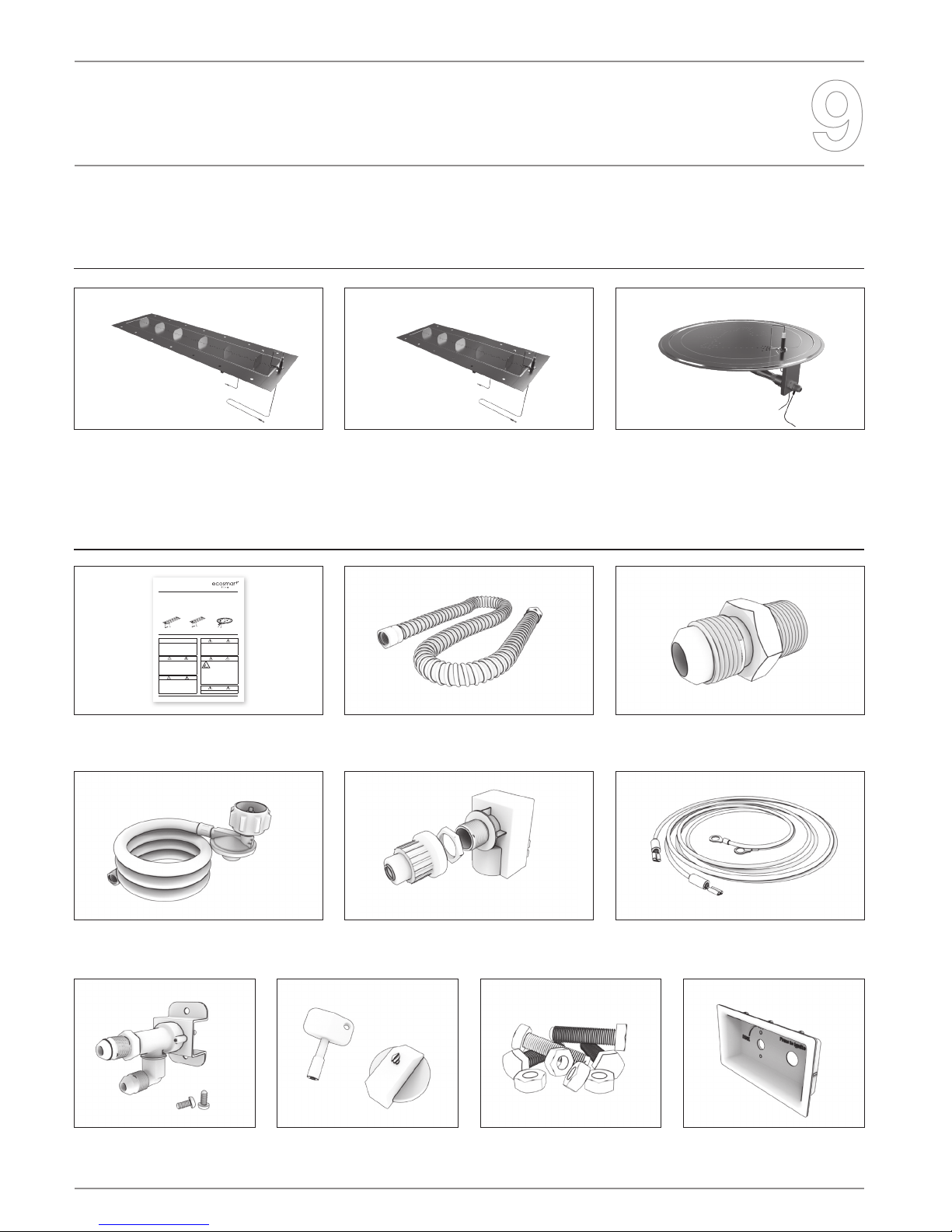
Standard Equipment Received
Please ensure that all items have been received. The burners include the minimum equipment required to operate the burner safely.
Burners
Included items
Long Gas Burner - ESF.1.B.G35 Medium Gas Burner - ESF.1.B.G28 Round Gas Burner - ESF.1.B.G16
Operations Manual
Flexible gas line (ships connected to burner)
Orice #43 (LP - Ships Connected)
Orice #31 (NG)
LP Hose & Regulator (10’)
Valve and Screws
(to connect to the control panel)
Sparker Box
4 x bolts/nuts for attaching linear
burner to Adapter Plate
Control Knob and Key
Grounding Wire 36”
(ships connected to burner)
Control Panel
(does not ship with burner /
ships with surround unit)
WARNING
Improper installation, adjustment, alteration,
service, or maintenance can cause injury or
property damage. Read the installation and
maintenance instructions thoroughly before
installing or servicing this equipment.
DANGER
CARBON MONOXIDE HAZARD
This appliance can produce
carbon monoxide which has
no odor.
Using it in an enclosed space
can kill you.
Never use this appliance in
an enclosed space such as a
camper,tent, car or home.
WARNING
For outdoor use only
CAUTION
DO NOT DISCARD THIS MANUAL
•Importantoperatingandmaintenance
instructions included.
•Read,understand,andfollowthese
instructions for safe installation and operation.
DANGER
If you smell gas:
•Shutogastotheappliance.
•Extinguishanyopename.
•Ifodorcontinues,keepawayfromthe
appliance and immediately call your gas
supplierorredepartment.
WARNING
Do not store or use gasoline, or other
ammablevaporsandliquids,inthevicinity
of this or any other appliance.
An LP-cylinder not connected for use shall
not be stored in the vicinity of this or any
other appliance.
INSTALLATION,
OPERATION
AND MAINTENANCE
MANUAL
LONG GAS BURNER
ESF.1.B.G35 13.5lbs/6.13kg
MEDIUM GAS BURNER
ESF.1.B.G28 12.8lbs/5.8kg
ROUND GAS BURNER
ESF.1.B.G16 8.6lbs/3.9kg

© Copyright 2004 - 2016 EcoSmart Inc. All rights reserved. V251115
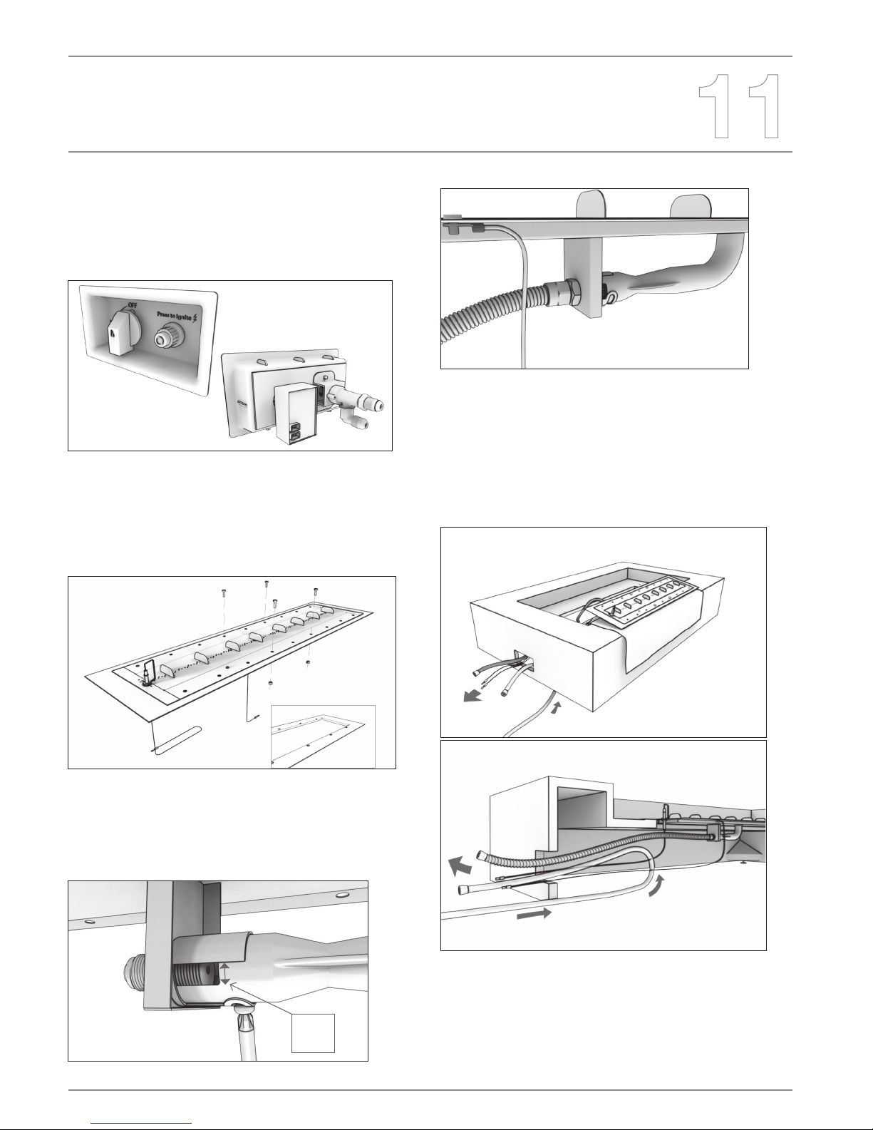
Standard Equipment Received
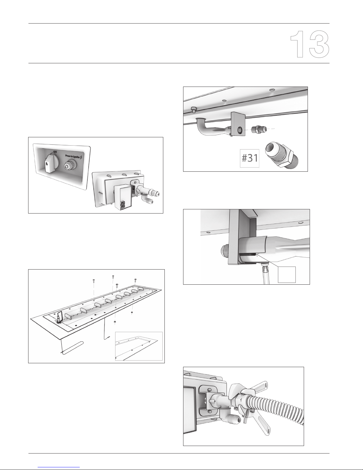
Assembling the control panel
Conrm you have received all necessary parts as illustrated on page 9.
1. Attach the valve to the back of the control panel using the provided
screws. Valve must be installed as shown in drawing (with outlet on
top and inlet on bottom).
2. Remove the sparker cover and plastic nut from the sparker box.
3. Place the sparker behind the control panel and insert sparker box
into control panel.
4. From the front of the control panel, secure the sparker by attaching
the plastic nut.
5. Insert AAA battery, ensuring the + direction of the battery is facing
outward when installed.
6. Screw on the sparker box cover to hold battery in place.
1.
4.
2.
5. 6.
3.
ENGLISH
Burner Assembly - Propane
PROPANE
1. Unpack burner box. Remove all items and check against the items
listed on page 9 of the manual to ensure all parts needed are ready.
2. Ensure you have assembled the control panel, as outlined on page 10.
For the Round Burner go to step 4.
3. Linear burners only: (this step is not required for round burners)
Attach the burner to the adapter plate (found inside the Surround Unit)
using the four bolts and nuts provided.. Ensure burner is attached
to the at side of the adapter plate marked “For Gas Burner Only”. If
experiencing issues lining up the holes of the burner and the adapter
plate, please rotate the burner 180 degrees and try again.
4. The exible gas line is already attached to the burner orice. Conrm
the air shutter is open 1/4 in (6.4mm) on each side of air shutter and
ensure connection of exible gas line is tight.
5. Ensure ignitor wire is secured to bottom of Ignitor.
6. Ensure grounding wire is secured to bottom of burner.
1/4”
(6.4)
7. Place a protective towel over the unit. Carefully place the burner
on Surround Unit near opening without inserting burner into the nal
location. Feed the exible gas line, grounding wire and the Ignitor wire
through the burner location and out the control panel opening of the
Surround Unit (located on the side of the Surround Unit).
8. Slide the black propane tank hose under the Surround Unit and out
through the control panel opening. The other end of the black propane
hose with the regulator will attach to the propane tank.
9. Using two adjustable wrenches, attach the exible gas line to the top
valve tting (outlet). Do not overtighten.
10. Using two adjustable wrenches, attach the propane tank hose to the
bottom valve tting (inlet). Do not overtighten.
© Copyright 2004 - 2016 EcoSmart Inc. All rights reserved. V251115
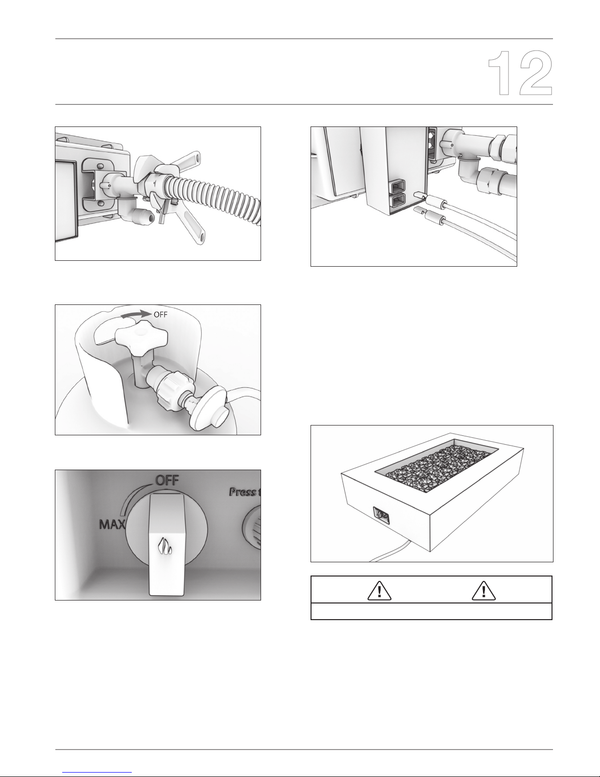
Burner Assembly - Propane
11. Ensure propane tank is in the OFF position. Attach propane hose
and included regulator to propane tank.
12. Ensure the control knob (or “key”) is in the OFF position.
13. Use a leak detecting solution to check all connections before
operation.
14. Plug the Ignitor wire and grounding wire into the back side of the
sparker. These wires can be plugged into either port on the back side of
the sparker box.
15. Insert the fully assembled Control Panel into the side of the Surround
Unit, feeding the cables and wires back in under the unit as needed until
the control panel is rmly in place. Ensure the control knob (or “key”) is
in the OFF position.
16. Place the burner in the unit and remove the protective towel.
17. Fill burner area with included decorative media. Ensure burner
is completely covered before igniting the burner or burner can be
damaged.
Spread Lava Rock out evenly over burner area. Use all Lava Rock
provided for best aect. Keep clear of spark to avoid accidental
blockage. Must be spread evenly for even ame.
WARNING
Do not burn without Lava Rock on burner.
ENGLISH
Burner Assembly - Natural Gas
NATURAL GAS
Note: Connection of this product to Natural Gas must be
completed by a licensed gas plumber / installer only. Do not
attempt to install this product with Natural Gas without a licensed
installer present.
1. Unpack burner box. Remove all items and check against the items
listed on page 9 of the manual to ensure all parts needed are ready.
2. Ensure you have assembled the control panel, as outlined on page 10.
For the Round Burner go to step 4.
3. Linear burners only: (this step is not required for round burners).
Attach the burner to the adapter plate (found inside the Surround Unit)
using the four bolts and nuts provided. Ensure burner is attached to
the at side of the adapter plate marked “For Gas Burner Only”. If
experiencing issues lining up the holes of the burner and the adapter
plate, please rotate the burner 180 degrees and try again.
4. Using two adjustable wrenches, remove the ex line from the burner orice.
5. Using two adjustable wrenches, remove the #43 orice from the gas
inlet of the burner.
6. Insert orice #31 in the gas inlet of the burner and tighten using two
adjustable wrenches. Do not over tighten.
7. Re-attach the exible gas ex line to the orice. Do not over tighten.
8. Adjust air shutter to between 1/16 in (1.6mm) open to completely
closed, on each side of air shutter.
9. Ensure ignitor wire is secured to bottom of Ignitor.
10. Ensure grounding wire is secured to bottom of burner.
11. Place a protective towel over the Surround Unit. Carefully place
the burner on Surround Unit near opening without inserting burner
into the nal location. Feed the exible gas line, grounding wire and
the Ignitor wire through the burner location and out the control panel
opening located on the side of the Surround Unit.
12. Using two adjustable wrenches, attach the exible gas line to the
top valve tting (outlet). Do not overtighten.
1/16”
(1.5)

© Copyright 2004 - 2016 EcoSmart Inc. All rights reserved. V251115
Burner Assembly - Natural Gas
13. Route the natural gas line from below the Surround Unit out through
the control panel opening.
14. Using two adjustable wrenches, attach the natural gas line to
the bottom valve tting (inlet). Do not overtighten. It is strongly
recommended to place a manual shuto valve in the natural gas line
before it reaches the valve on the control panel.
15. Ensure the control knob (or “key”) is in the OFF position.
16. Use a leak detecting solution to check all connections before
operation.
17. Plug the Ignitor wire and grounding wire into the back side of the
sparker. These wires can be plugged into either port on the back side
of the sparker box.
18. Insert the fully assembled Control Panel into the side of the
Surround Unit, feeding the cables and wires back in under the unit as
needed until the control panel is rmly in place.
19. Place the burner in the unit and remove the protective towel.
20. Fill burner area with included decorative media. Ensure burner
is completely covered before igniting the burner or burner can be
damaged.
Spread Lava Rock out evenly over burner area. Use all Lava Rock
provided for best aect. Keep clear of spark to avoid accidental
blockage. Must be spread evenly for even ame.
WARNING
Do not burn without Lava Rock on burner.
ENGLISH
Lighting and Operating
To Extinguish
Turn control valve to “OFF” position or close ball valve. Close valve on
propane tank while not in use.
Initial break-in procedure: When you light the appliance, you may
notice that it produces heat which may have an odor. If you feel this
odor is excessive it may require an initial three to four hour continuous
burn on high.
WARNING
FIRE RISK – HIGH TEMPERATURES
Keep combustible household items away from appliance.
• Do NOT obstruct combustion and ventilation air.
• Do NOT place combustible items on top of or near appliance.
• Keep furniture, draperies away from appliance.
• Do NOT use, lantern fuel, kerosene, charcoal lighter
uid, bioethanol or similar liquids in this appliance.
• Combustible materials, ammable liquids, or vapors may ignite.
FOR YOUR SAFETY, READ BEFORE LIGHTING
WARNING! If you do not follow these instructions
exactly,areorexplosionmayresultcausingproperty
damage, personal injury, and/or loss of life.
A.This appliance can be lit electronically or with a match. When lighting,
follow these instructions exactly.
B.Before lighting, smell all around the appliance area for gas. Be sure
to smell next to the base of the appliance because some gas is heavier
than air and will settle on the oor.
WHAT TO DO IF YOU SMELL GAS:
• Do not try to light any appliance.
• Do not touch any electric switch, do not use any phone nearby.
• Immediately call your gas supplier from a neighbors phone. Follow gas
supplier’s instructions.
• If you cannot reach your gas supplier, call the re department.
C. Use only your hand to turn the gas control knob on propane tank (if
equipped), never use tools. If the valve won’t turn by hand, don’t try to
repair it, call a qualied service technician. Force or attempted repair
may result in a re or explosion.
D. Do not use the appliance if any part has been underwater.
Immediately call a qualied service technician to inspect the appliance
and replace any part which has been underwater.
E. The gas pressure regulator provided with this appliance must be used.
This regulator is set for an outlet pressure of 10.5in (267mm) water column.
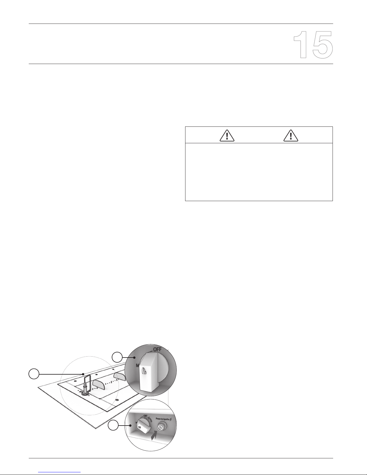
Lighting Instructions
1. Depress sparker button and verify a spark is being produced
between the electrode tip and receiving probe.
2. Ensure control panel valve is in the “OFF” position and slowly open
valve on propane tank. If using natural gas or whole-house LP, open ball
valve. If not using a control valve, skip this procedure until step 3.
3. Depress sparker button and continue holding button while turning
knob to the “ON” position. Release button once ame is present.
WARNING: If the ame does not ignite within 5-10 seconds turn
the gas “OFF” and wait for 5 minutes before re-attempting to ignite.
Failure to follow this instruction may result in a volatile ignition due to
the build up of vapors.
1.
2.
3.

© Copyright 2004 - 2016 EcoSmart Inc. All rights reserved. V251115
Troubleshooting
Symptom Possible Causes Corrective Actions
1. Appliance won’t light
A. No LP in tank, or NG main not turned on. Check the LP (propane) tank. You may be out of
gas. Or check Natural Gas valve at main.
B. Plugged burner orice. Check the burner orice for stoppage. Remove
stoppage.
C. No spark igniting burner Refer to ignitor on section 7 below.
2. Low ames or
won’t stay lit A.
Manual shuto valve (on/o control knob)
open or not in- stalled between LP tank and
appliance.
Close LP tank and manual shuto valves. Open LP
tank valve rst, THEN the manual shuto valve.
3. Blue Flames
A.
This is a result of normal operation and
ames will begin to yellow as unit is allowed
to burn for 16-20 minutes.
No action required.
B. Improper air/fuel mixture related to air
shutter position.
Close air shutter. (for LP, leave ¼in [6.4mm] open,
Natural gas 1/16 in [1.6mm] open).
4. Metallic noise A.
Noise is caused by metal expanding and
contracting as it heats up and cools down,
similar to the sound produced by a furnace
or heating duct. This noise does not aect
the operation or longevity of the appliance.
No action required.
5. Lava rock cracking or
splitting A. Heat and/or abrupt temperature changes. This is a property of lava rock and may happen
occasionally. Do nothing. This is completely normal.
6.
Ignitor makes clicking
sound but no visible spark
is produced
A. Ignitor is improperly grounded. Check all wire connections at back of sparker box.
B. Ignition or ground wire not plugged in. Ensure ignitor wire and grounding wire are securely
attached to burner.
C. Ignitor tip set too far from grounding probe.
Check that tip of ignitor is within ¼ in (6.4mm)
of grounding probe. Gently bend Ignitor tip or
grounding probe by hand to achieve a smaller gap.
7. Ignitor does not spark or
make a ticking sound
A. Battery low, Not installed, Installed
incorrectly.
Ensure that a fresh AAA battery is installed Positive
(+) side facing outward toward the sparker cap.
B. Corrosion on battery contacts.
Check contact at the bottom of the battery cavity
for corrosion. Clean with a small piece of sandpaper
or a le.
C. Battery cap not screwed down completely.
If the cap cannot be screwed down tight enough,
the battery will not make a proper connection with
the sparker and it will not work. Be sure to use a
thin surface such as 20-22 gauge sheet metal to
mount sparker in.
ENGLISH
Service and maintenance
Although the frequency of appliance servicing and maintenance will
depend on use and the type of installation, a qualied service technician
should perform an appliance check-up annually.
Storage of an appliance indoors is permissible only if the cylinder is
disconnected and removed from the appliance.
Stainless steel will rust or corrode over time if contamination or
debris is not cleaned or removed immediately. When not in use, it is
recommended that you protect your replace from water damage or
corrosion with a protective cover.
WARNING
Risk of injury or property damage.
Before servicing:
• Turn o utilities to appliance
• Ensure appliance is completely cooled
Maintenance and Service Tasks
Likeallreandreplacesystems,it’simportanttorunthroughregularsafetychecks.Pleasetakethetimetofamiliariseyourself
(andanyotherusers)withthesafetyproceduresassociatedwithusingyourrepit.
Inspect Maintenance Tasks
Burner Assembly
1Remove decorative lava rock and examine burner. Vacuum and wipe out as needed.
Use caution when cleaning these areas
2 Inspect for warping and corrosion. Repair as necessary
3Check the hose connecting the LP gas cylinder to ensure it is not damaged. Replace
as necessary.
4 Verify air shutter area is clean
Burner Ignition and Operation
1 Verify all gas connections are tight and leak-free
2Clean burner top, inspect for plugged ports, corrosion, or deterioration. Replace
burner if necessary.
3Inspect for ame problems.
4Verify air shutter is clear of dust and debris and is in correct position for the gas type
being used.
5Inspect orice for soot, dirt, or corrosion
6Verify manifold and inlet pressures. Adjust regulator as required.
Gas Hose with Regulator 1 The gas hose with regulator supplied with appliance must be used for LP installations.
The replacement must be those specied by the appliance manufacturer
WARNING
Annual inspection by qualied technician recommended.
Check:
• Obstructions of combustion and ventilation air.
• Condition of burner assembly
• Burner ignition and operation
• Burner air shutter adjustment
• Gas connections and ttings
Risk of:
• Fire
• Delayed ignition or explosion
• Exposure to combustion fumes
• Odors
© Copyright 2004 - 2016 EcoSmart Inc. All rights reserved. V251115
Reference Materials
Replacement Parts SKU
LP / NG BURNER
Burner Assembly EcoSmart Fire Long Gas Burner ESF.1.SU.G35
Burner Assembly EcoSmart Fire Medium Gas Burner ESF.1.SU.G28
Burner Assembly EcoSmart Fire Round Gas Burner ESF.1.SU.G16
Control Key ESF.1.P.KEY
Control Knob ESF.1.P.KNB
Fastener Kit for Adapter Plate ESF.1.P.FST
Flex Line (36”) ESF.1.P.F36
Gas Control Panel - Flat ESF.1.P.CPF
Gas Control Panel - Urth ESF.1.P.CPU
Grounding Wire 36” ESF.1.P.G36
Igniter ESF.1.P.IGN
LP Hose & Regulator (10’) ESF.1.P.H10
Orice #31 ESF.1.P.O31
Orice #43 ESF.1.P.O43
Sparker Box ESF.1.P.GSB
Valve Components ESF.1.P.VAL
MODELS
Linear Burner Adapter Plate (G35) ESF.1.P.A35
Service Parts List

ENGLISH
Reference Materials
Limited One Year Warranty
EcoSmart Inc extends the following warranty for GB Series decorative
outdoor gas re products used in the United States of America or
Canada. Dealers and employees of EcoSmart Inc have no authority
to make any warranty or authorize any remedies in addition to or
inconsistent with the terms of this warranty. This warranty gives you
specic legal rights. You may also have other rights that vary from state
to state.
EcoSmart Inc warrants that this GB Series decorative gas appliance (the
“product”) will be free from defects in material and workmanship for a
period of one year from its date of purchase. Stainless steel parts and
assemblies carry a limited lifetime warranty. This warranty is subject to
the conditions, exclusions and limitations described below.
This warranty applies only to the original owner of the Product and is
non-transferable. EcoSmart Inc obligation under this warranty does
not extend to damages resulting from (1) assembly, operation or
maintenance of the Product not in accordance with the Installation/
Assembly Instructions, Operating Instructions and the Listing Agency
Identication Label furnished with the Product; (2) installation or use
which does not comply with local building codes and ordinances;
(3) shipping, improper handling, improper operation, abuse, misuse,
accident or unworkmanlike repairs; (4) use of fuels other than those
specied in the Operating Instructions; (5) Installation or use of
components not supplied with the Product or any other components not
expressly authorized and approved in writing by EcoSmart Inc; and/or
(6) modication of the Product not expressly authorized and approved
in writing by EcoSmart Inc. Any of the circumstances described in
the previous sentence voids this warranty. This warranty is void if the
Product or any component has been removed, repaired, or replaced
before EcoSmart Inc has been aorded a reasonable opportunity to
inspect the Product.
This warranty is limited to the replacement or repair of defective
components or workmanship and EcoSmart Inc may fully discharge its
obligations under this warranty by repairing or replacing, at its discretion,
the defective components. EcoSmart Inc will provide replacement parts
at no charge and will pay reasonable freight costs related to replacing
or repairing defective components under this warranty. The maximum
amount recoverable under this warranty is limited to the purchase price
of the Product and, if EcoSmart Inc is unable to provide replacement
or repair in an expedient and cost-eective manner, EcoSmart Inc may
discharge all obligations under this warranty by refunding the purchase
price of the Product.
EXCEPT TO THE EXTENT PROVIDED BY LAW, ECOSMART INC
MAKES NO EXPRESS WARRANTIES OTHER THAN THE WARRANTY
EXPRESSED HEREIN. THE DURATION OF ANY IMPLIED WARRANTY
IS LIMITED TO THE DURATION OF THE WARRANTY SPECIFIED
ABOVE. IN NO EVENT SHALL ECOSMART INC BE LIABLE FOR ANY
INCIDENTAL OR CONSEQUENTIAL DAMAGES CAUSED BY DEFECTS
IN THE PRODUCT. Some states do not allow limitations on how long an
implied warranty lasts, or do not allow exclusion or limitation of incidental
or consequential damages, so these limitations may not apply to you.
To obtain service under this warranty, you must:
1. Send written notice of the claimed condition to:
3641 Holdrege Avenue, Suite B, Los Angeles CA 90016 USA
2. Arm that you are the original owner of the Product.
3. Photos or video of issue will be required in order to asses the warranty
claim.
4. Provide EcoSmart Inc reasonable opportunity to investigate the claim,
including reasonable opportunity to inspect the Product prior to any
repair or replacement work and before the Product or any component
of the Product has been removed.
This manual suits for next models
2
Table of contents
Other EcoSmart Fire Burner manuals


Popular Burner manuals by other brands


Wayne
Wayne P250AF owner's manual

DS Produkte
DS Produkte BY-EWB-2000-A01 manual

Mason-Lite
Mason-Lite OpalEscence LDB24L-EN Installation & operation manual

Riello Burners
Riello Burners PRESS 100 N Installation, use and maintenance instructions

Unigas
Unigas HTLX92R installation manual

baltur
baltur GI Series Instruction

Comtherm
Comtherm PP Series Installation & maintenance manual

Riello
Riello RS 250/M Installation, use and maintenance instructions

HomeTech
HomeTech Q1B-CH-2000ST manual

Bentone
Bentone LME21.550C2 Installation and maintenance instruction

Giersch
Giersch MG2-ZM-L installation instructions

Riello
Riello P 140 T/G Installation, use and maintenance instructions