EcoSpeed Electric Mountain Drive Guide

ElectricMountainDriveComponents
DriveUnit
(connectorsmaydiffer
dependingonmotor)
FreewheelingCrankset
(tripleshown)
MotorChainAd-
justPlate
Frame Collar
ReturnSideIdlerMounting
Holes
Motor/Gearbox
Unit
PhaseCon-
nectors

EcoSpeedMotor
Controller
OtherParts
ElectricMountainDriveComponents
PhaseLeads
ThrottleLead
HallSenseLeads
PowerLead
EcoSpeed’sDigital
MotorController
ReturnChain
Idler WaxLube Throttle MotorChain
AdjustCup
LockRing
Adjust
Cup Insert
Tool
Possible
Clamp-sets

Congratulations onyourpurchaseofEcoSpeed’s ElectricMountainDrive, Type2.TheType2Electric
MountainDriveis theworld’sbestmulti-speed,throttleoperated,electric-assistconversionandtheonly
electric-assistdesigned specificallyforthepower needs of shortwheelbaserecumbentbikes andtadpole
trikes.
Theseinstructions will guideyoustepbystepthroughwhatwehopewill bea simpleand painless instal-
lationof yourEMtnD.Themechanicalskills involved aremodestand,wegiveyouhints andtips atevery
stepthatreflectwhata professionalmechanicknows.Ifatanytimeyouhaveproblems,call us at1-866-
EcoSpeed (866-326-7733)forfriendlytechnicalassistanceore-mailus at support@ecospeed.com.
A word onhowtheseinstructions areorganized: Eachstepis under a majorheading–Step1:,Step2:,
etc.Ifyou’veinstalled anEMtnDbefore,youcanjustread themajorheadings and ignore theexplana-
torytext.Beloweachmajorheadingis a listofsub-steps.Theimportantinformationineachsub-stepis
inbold text.Ifyou’re a competentbikemechanic,youcanjustread theboldtextand safelyignore the
rest.Theremainingtextisthere toclarifythingsfornon-mechanics. We’vealsoincluded tips andhints
inItalics.
SincetheEMtnD2 will fitbothbikes andtrikes,forsimplicitywewill justrefer tothemall as bikes
unless weare pointingoutsomethingthatapplies onlytotrikes.Inthis firstversionof theEMtnD2 man-
ual,mostphotos showtheEMtnD1onanuprightbike. Theinstallations steps arethesameexceptthe
unitclampstothefrontboomrather thanthedowntubeas showninthephotos.
Beforegettingstartedcheckthatall thepiecesneededwereincludedinyourshipment:
Checkthepackinglistincludedwithyourshipment.
Youwill also needthefollowingtools:
1)2.5mm,3mm,4mm,5mm,and8mmhex(orAllen)wrenches. (Thestandard “L”shaped
hexwrenches sold atbikeshops andhardwarestores.Getlonghandled versions ifpossible.)
2)10mmbox oropenendwrench.
3)8mmand10mmnutdriversorsockets.Also14mmifyourbottombracketusesthissize
bolt.
4)Wireclippersorscissors.
5)Small screwdriver. (Foradjustingfrontderailleur.)
6)Needlenosepliers.
7)Crankpullertool. TheParkToolCWP-6would beanexampleofthis (Standard bikerepairtool.
Availablefromalmostanybikeshop.)
8)Bottom brackettool. Suchas ShimanoTL-UN74. (Standard bikerepairtool.Availablefromal-
mostanybikeshop.)
9)15mmpedalwrench. TheParkToolPW-5wouldbeanexampleof this (Standard bikerepairtool.
Availablefromalmostanybikeshop.)
10)Torquewrench(optional). A small one, readingininch-pounds.
11)PinSpanners. Boththered and greenhandledParktoolpinspanners. Onceyouhaveall theparts
and toolsyouneed,it’stimetoclear a nicespacetowork,find severalof hours time, and gettoit!

Ifyouhaven’thad yourbiketunedupbyyourlocal
bikeshopina while, nowwouldbea good time.
InstallingtheEMtnDwill placeextra stress onyour
bikesoit’s importantthatitbeintopcondition.
Step 1:Findawayto secureyourbikewhile
working. (photo 1)
Trikes cansimplyberested onallthree wheels.
Placingthetrikeonlargetabletopcanmakeiteas-
iertoworkon.
Notethatthefollowingtwo stepswould takeany
competentbikeshopabout5 minutes todo.Ifyou
would rathernot hasslewiththem,takeyourbike
to yourlocal bikeshopand havethemremovethe
cranksetand bottombracket.Thenstartatstep4.
Step 2:Removecrankset.
Removethecranksetincludingtheleftarm.
Leavechainhangingfromfrontderailleur.
Thetoolsinvolvedwill differbetweencrank
modelsandbrands.
Thecranks areheld inplacebybolts,sometimes
concealedunder caps.Removeusinga socketor
hex wrench. Oncethebolts areout,useyourcrank
puller tooltopull thecranks off of thebottom
bracketaxle(photo2).
Step 3: Removebottombracket.
TheEMtnD isdesignedtoworkwithframes
thattakestandard1.37”x24tpi,68mm wide
bottom brackets.Ifyours is not,youwill need
tofind a compatiblewidebottombrackettouse
with theEMtnD.Thesupplied oneuses a 127mm
squaretaper axle. There is quitea bitofadjustabil-
itybuiltintotheEMtnD,soa similar oneshould
workfine.
There are differentbottombrackettools,soyou
will need tousetheoneappropriateforyourbike.
Photo3 shows thetoolusedforShimanocartridge
bottombracketnuts suchas theonesupplied with
theEMtnD.
Notethatthe right nutis left-handthreaded,i. e. it
tightens byturningleftand loosens byturningto
theright(clockwise).The left nutuses standard
right handthreads (loosens counterclockwise).
Removetheleftnutfirst.Thecartridgewill comeoutalongwiththeright nut.
(1)BikeonWorkTable
(2)RemovingCrankwithCrankPuller
(3)RemoveBottom Bracket

Step 4:Install thenewbottombracketandat-
tachtheEMtnD
Slip the BB cartridgeandrightsidenut
throughthe collaron the EMtnD.Sup-
portthe weight ofthe EMtnD,soasnot
to damagethe threads,andscrewin the
right sideBBnut.(Photo 4A+B)
Youmaywantto havean assistantholdthe
unitwhile youperformthisstep.Thethreads
ontheBB nuts arefragile aluminum,so be
verycareful when first engagingthethreads.
Rememberthattherightnutislefthand
threadedso turnitcounterclockwiseto engage
thethreads.
(Trick:toavoidcross threading, gentlypress
thenutintothebikeframewhileturning
clockwise.Youwill feel aperiodicclickasthe
endof thethreaddropsintothegroovein the
framethreads.When youfeel theclick,stop
turningclockwiseandturn counterclockwise
toengagethethreads.)
ScrewintherightsidenutuntiltheEMtnD
collarispressedagainst thebikeframebutdo
not tighten.(Photo 4B)
Screw in the leftsidenutthroughthe
lefthandcollar,don’ttighten.Thisin-
volvesthe useofaproprietarytool
madeto fit ourspecialleftsidecup.
(Photo 4C+D)
Youuseastandardpinspanner,insert its ends
into thespecial tool,andusethisto threadin
theleftsidecup.Youcan then threadonthe
lockring, whichwill not betightenedyet.
When you’redone,theEMtnDwill behanging
off ofthebottombracketbythecollars as
showninPhoto6.
Step 5:SwingtheEMtnDupagainst thebot-
tomofthetrike’sboomtubeandinstall clamp
sets.
Iftheclamps interfere withexposed cables,they
canbeenclosed ina shortlengthof cablesleeve
and routed aroundtheclamps. (4C)LeftSideBB NutPartly Installed
(4B)UsingaPark Tool
(4A)InstallingNewBottom Bracket

Most kits will havean adjustable strap system
thatattachesthefrontoftheEMtnDto the
frame.Theprimarymotor platehascutouts to
accommodatetheheadoftheclamp,allowing
itto beoutofthewayandstreamlined.
Tighten theclampuntil thereissignificant
tensionholdingthemotor tothedowntube.
As youdothis,feedtheemergingclamptail
into thesuppliedpieceofshrinkwrap,thiswill
preventanyexposededges.When clampis
tight,shrinkthiswithaheatgun,blow-dryer,
pen torch,or lighter.If usingflame,besure
not to burnthebikeor yourself!(Photo 5)
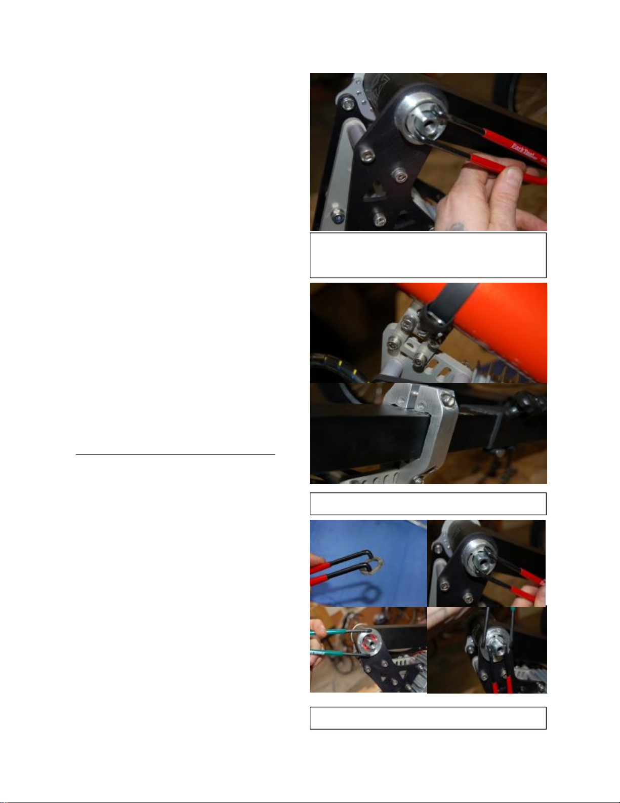
If youhaveamachinedclampfor yourappli-
cation,therewill be2M5bolts holdingitto
themotor frame,and1M6boltholdingthe
halvestogetherabovethebike’sboom.
Oncebothhalvesareinstalled, tighten theM5
bolts andnuts holdingtheclampstheEMtnD
unit.Next,tighten theM6boltandnut.If you
haveatorquewrench,tighten themto 90inch-
lbs(10N-m).Otherwisetighten firmlybutnot
so muchastoclosethegap between theclamp
topmorethan acouple ofmm.
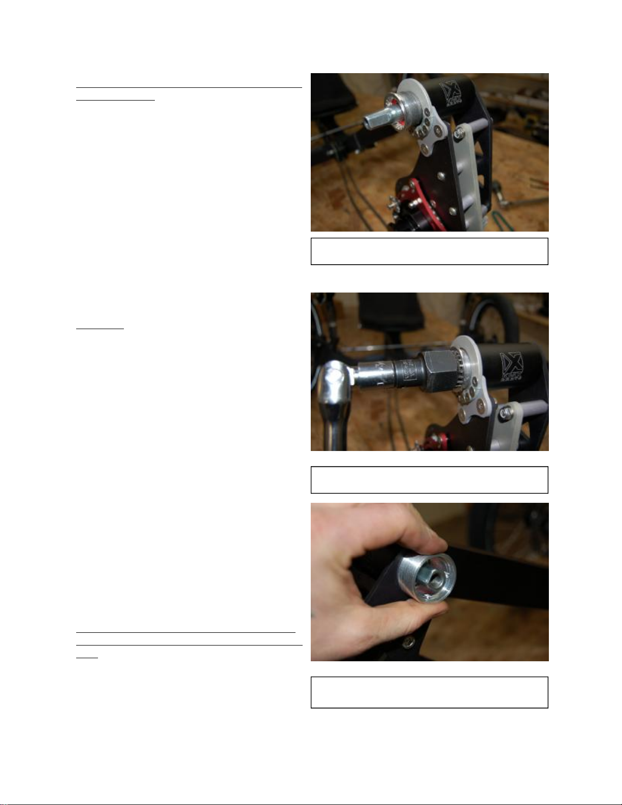
Step 6:FinishattachingtheEMtnDunit.
Makesureall clampboltsorstrapistight.
Tightenbothbottom bracketnuts.
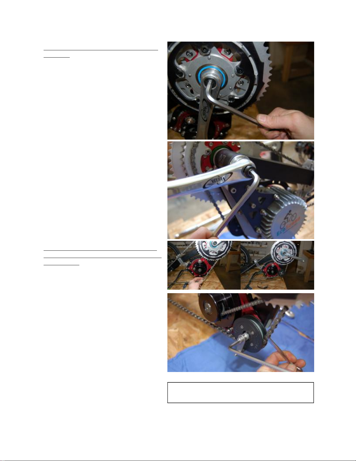
Tighten thebottombracketinall thewaybe-
forescrewingtheadjust cupin,leavingjust
enoughthreadsfor thelockring. Useyourpin
spanners,andwhen thecupisinall theway,
holditinplaceandtighten thelockringup
against thecollar.
Itmaytakesometimeto getthehangofusing
thespannerwiththeEcoSpeedtool,just take
yourtimeanditwill come.Donot losethespe-
cial tool,asyouwill needitto changebottom
brackets,or removethemotor incaseyou
changetrikes,etc.(Photo 6)
(4D)EMtnDHangingfromCollaron
Bottom Bracket,UsingProprietary
Tool.
(6)AdjustCupandLock-ringInstall
(5)ClampsInstalledOn Frame

Step 7:Install thefreewheelingcrankset.
(photo 7)
Install theleftsidecrankarm andthe
freewheelingcrankandchainringas-
semblyontheright.Tighten boltsfirmly
sothatbotharmsarepressedontothe
bottom bracketaxleasfarastheywill
go.
It’s importantthattheright sidecrankarmis
firmlyseatedontotheBB axleforcorrectalign-
mentof themotordrivechain.
This stepinvolves puttingthedrivechainonto
thesmall chainring, and installingtheReturn
ChainIdler inoneofthetwooptionalplace-
ments.Thepurposeof theidler is toroutethe
returnsideof thebikechainaroundthegear-
box.Inthephotoshowntheidler is inthefor-
ward position.This is thedesired position,but
dependingonthebikeyoumayhaveshifting
problems and needtoplacetheidler inthe
rearward position.
As itwill behard totellwhichpositionwill
workbestduringinstallation,putitinthefor-
ward positiontostartwith,andthenchangeit
ifthere are problems.
Step 8: Install themotor chainandalign
thegearboxsprocketto thechainringmo-
tor sprocket.
Install themotorchainusingneedle
nosepliers.
Thegear boxrolls easilyinonedirection,insert
thechainand roll itaround thesprocketand
throughtotheother side. Nowwrapitaround
themotorsprocketandbringtheends together
with pliers as shown.(Photo8)
Theends attachbyinsertingthe2pinned link,
coveringitwith thesmall plate, andthencon-
nectingthemwiththeclipthatshould seat
firmlyintothepin’s slots.(Photo8)
Alignthemotorchain.
Sightdownthelineof themotorchain,anduse
theredtertiaryplates’setscrews and adjust-
mentboltstostraightenouttheline, where itis
notgoingtorubagainsteither chain-ring
guards,and will givethebestpower transfer possible. Youmaywanttousea thinstraight edge, suchas a
(7)InstallingCrankset,DriveChain,and
Return Chain Idler

metalruler, tohelp yousight downthechain-line
tocheckalignmentofthegearboxsprocketwith
thechain-ringmotorsprocket.(Photo8)
Thesetscrews cangoina littlemore thanhalf
wayintotheplateifneeded forproper alignment.
Whenthedesired chainlineis found,tightenthe
pinchbolts nexttothesetscrews.Itis possibleto
putexcessiveforceontheplate,a good guideline
is totightendownuntilyousee thered tertiary
platestarttobend slightly,and thenleaveitright
there.
Step 9: Installall wiring
Whilewiringupthesystem,donotsecure anyof
thewires totheframeuntileverythingis inplace
and tested.This will insure thateverythingis
workingand routed mostefficientlybefore using
theincluded zipties.
Install thethrottle
Ifyourbikehastwistshifters,remove
rightsidegripandshifterandinstall the
thumbthrottlebetweenshifterandbrake
asshowninphoto 9A.
Youmayneed tomovetherightbrakelever to
thelefttomakeroomforthethrottle. Thethrot-
tleslides ontoyourhandlebar and locks inplace
with a setscrewvisibleonthebottomofthe
throttlebody.
Reinstall thetwistshifter makingsure there is
enoughclearancetoallowfree movementofthe
throttlelever.
Ifyourbikehasthumbshifters:Install
accessorymountonleft handside,and
placethethrottleonitsoitisabovethe
bars.Photo 9B
Ifyoudon’t havethecorrectthrottletoworkwith
yourbar and shifter setup,contactEcoSpeed for
adviceand/ora differentthrottle.
Bothrightand lefthand mountingare possible. It
is uptoyourcomponentset-up,and whichyou
prefer.
Routethethrottlewiresothat itdoesn’timpairturningthebars,won’tsnagonanything,
andreachesthethrottleconnectoronthemotor.
(9A+B)LeftandRight ThrottlePositions
(8)InstallingChain,andAlign UsingSet
Screws

If youhaveaCycle Analyst for yourkit,install
itNow
TheCycleAnalyst will haveawheelsensor
andaconnectionbetween thebattery and
controller. Itis importanttomountitnow,as the
throttleand analystwires will followsomeofthe
samepaths.
MounttheController
Attachthe controllerto yourbikeusing
the includedadhesivefoam andcable
ties.Photo 9C showspossiblemounting
locations.
Thecontrollerisan electronicdevicethat
regulatesmotor speedandpowerlevelsinre-
sponseto asignal fromthethrottle.Itissmall
andlightandso maybemountedinanynum-
berofplaces.Theimportantconsiderations
arecooling—thecontrollershouldbeinopen
airandnot enclosed, andlocatingitso that
cablesfromthemotor andthrottle will reach.
MountyourBattery
See theincludedseparateinstructionsfor
yourtypeofbatterysystem.
Step 10:Connect all cables
Connectthefollowingcables:
1) Throttle. Black4-circuitJSTconnectoron
throttleplugs intomatchingconnectoron
throttle. Becarefulwhenpluggingintoavoid
bendingconnectorpins.(Photo10A)
2) 3Motorphasewires. Thesecanhavevari-
ous connectortypes dependingonthemotor
and controller combination.Thephasewires
are thethree heavycolored wires comingoutof
themotor.Connectthemtothematchingcon-
nectoronthecontroller. Ifthephasewires have
individualconnectors,matchthemaccording
tocolor.(Photo10A)
3) MotorHall SenseCable. A graycablecom-
ingoutof themotorendingina blackJSTcon-
nectorwith5 or6circuits.Plugintothecorre-
spondingconnectoronthecontroller. Becare-
fulwhenpluggingintoavoid bendingconnectorpins.(Photo10A)
4) MainPowerConnection. Theheavycablefromthebatterytothecontroller terminatingina gray
2-circuitMiniFitSrconnector.(Photo10B)
(10A)OptionalWireWrap,Enclosing
Connectors
(9C)PossibleControllerLocations
(10B)Main PowerConnector

WARNING: Donot route the phase
wires(2above)andthe Hall sensecable
(3 above)nextto eachotherovertheir
entirelength.Spacethem atleastan
inch(25mm)apartovermostoftheir
length.The highcurrentsin the phase
wirescan interferewith the low voltage
signalsinthe Hall cableanddestroythe
controller.
Step 11:CheckfrontDerailleurAdjustment
Triplechainringversiononly:Testfrontde-
railleuradjustmentandadjustasneeded.
It’sespecially importanttoadjust thederail-
leurso it doesn’tovershiftonthebigringanddropthebikechainontothemotorchain.
Ifyoudon’t knowhowtoadjustyourderailleuryoucanaskyourlocalbikeshoptodoit,orgoto:
http://www.parktool.com/repair/readhowto.asp?id=75
ontheParkToolCompanywebsiteforanexcellenthow-toarticleonfrontderailleuradjustment.
Singlechainringversiononly:Ifswitchingfrom atriplechainringtosinglechainring,
leavethefrontderailleurinplaceandadjustitso thatthebikechainiscenteredinthe
cage.
This will provideextra protectiontokeepthechainfromcomingoffthefrontsprocketonsharpbumps.
Step 12:FinishupandTest.
1)Withtherearwheelsuspendedoffoftheground,turnonthebatterypackswitchand
pressthethrottleto testthesystem.Runthebikethroughall ofthegearstomakesurethe
derailleurisproperly adjusted. Lookat themotorchainandverify that itisrunning
smoothly.Makesurethatall wiresareout ofthewayofall movingparts.Makesureaxle
boltsorskewersaretight
2)Onceyou’resatisfiedthat everythingisoperatingcorrectly,neatlytieall wiresout of
theway ofmovingpartsusingtheincludedcableties.
Proper adjustmentofthegears and makingsure thattherear cassetteandbearings areingood shapeis
especiallycriticalgiventheextra load thedrivetrainwillbesubjected to.Also,checkthattherear axle
skewer orbolts arefullytightened.Axlebolts shouldbetorqued toabout20ft-lbs (28Nm).Skewers
shouldbeas tight as youcancomfortablymakethem.Itis possibleforthemotortopull theaxleright
outof thedropouts iftheyare loose.
3)Roadtest. Runthroughall thegears makingsure theyare shiftingsmoothly.Usefull throttleineach
gear tocheckforskippingofthedrivechain.Keepspeeds lowatfirstuntilyou’re sure thateverythingis
functioningproperlyand youbecomefamiliar withridingwiththemotorassist.
Congratulations! Yourinstall iscomplete!
(11)AdjustingFrontDerailleur
Table of contents
Other EcoSpeed Bicycle manuals
Popular Bicycle manuals by other brands

Daymak
Daymak Wild Goose Mid Drive user manual

Cannondale
Cannondale Kids with Training Wheels quick start guide

Larry vs Harry
Larry vs Harry Shimano Steps E-Bullitt 6100 manual

Look
Look 795 LIGHT RS manual

Derby cycle
Derby cycle Rixe user manual

PLAYTIVE JUNIOR
PLAYTIVE JUNIOR 323252-1901 Instructions for use