FR FR
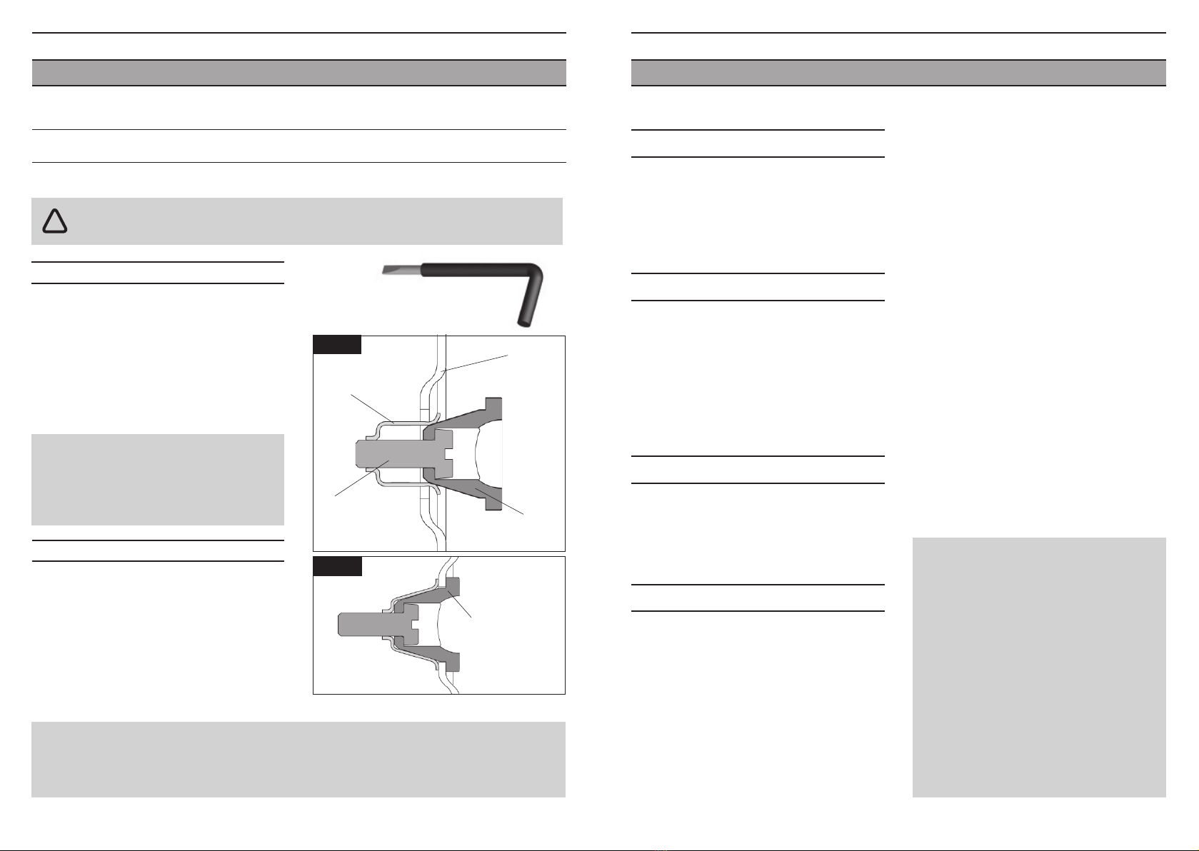
BUTÉE DE GAINE AMOVIBLE
Montage
Démontage
1/ S’assurer que la butée de gaine est en
position ouverte.
2/ Positionner la butée dans son logement, contre
la paroi en composite du cadre (Fig r).
3/ Serrer la vis de tension de 1Nm jusqu’au
maintien complet de la butée dans son
logement (Fig. s).
1/ Retirer la gaine éventuellement logée dans la
butée de gaine.
2/ Desserrer la vis de tension jusqu’à
désolidarisation de la butée de gaine.
3/ Extraire la butée. Si la butée oppose une
résistance au retrait, desserrer d’avantage la
vis de tension.
Le 695 Aerolight est équipé de butées de gaine amovibles servant au montage du groupe Shimano DI2 et Campagnolo EPS.
Attention ! Un serrage excessif de la vis de
tension peut conduire à la détérioration des
filets de la vis ou du ressort de maintien. Le
maintien de la butée ou son désengagement
peuvent s’en trouver affectés.
Attention! L’embout de la vis de tension est aplati de manière à éviter le désengagement du ressort de
maintien lors du desserrage. Veillez à ne pas forcer lors du desserrage sous peine de désengagement
du ressort de tension et de détérioration des filets de ce dernier ou de la vis de tension. Le maintien
de la butée ou son désengagement peuvent s’en trouver affectés.
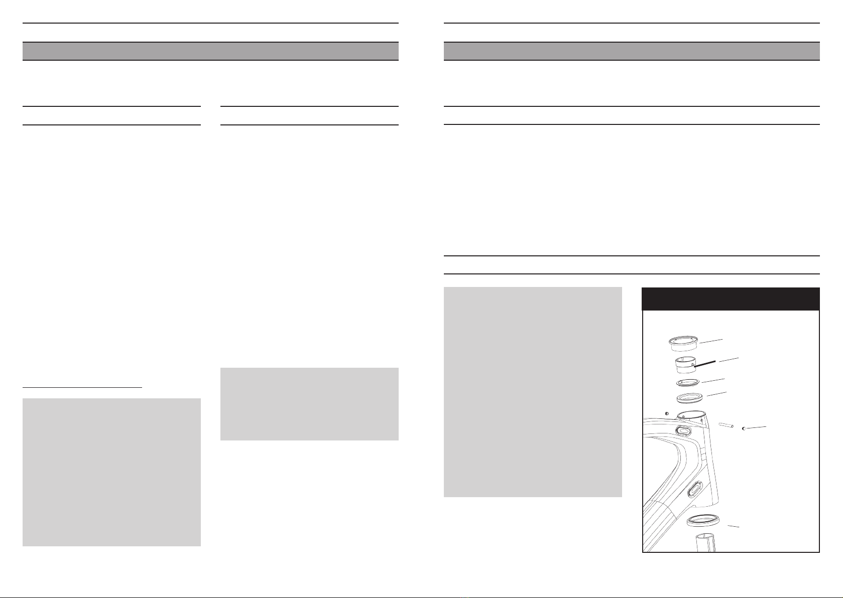
Ressort de maintien
Cadre
Vis de tension
Corps de butée
de gaine
Fig. r
Butée en position
dans son logement
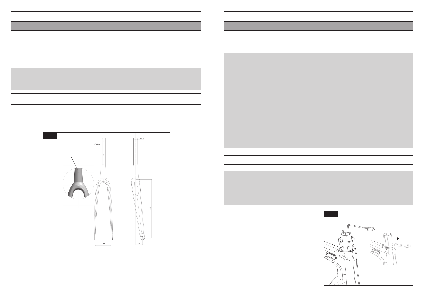
Outil montage/démontage
Utilisez exclusivement l’outil de montage / démontage prévu à cet effet et livré avec
le kit accastillage.
!
1716
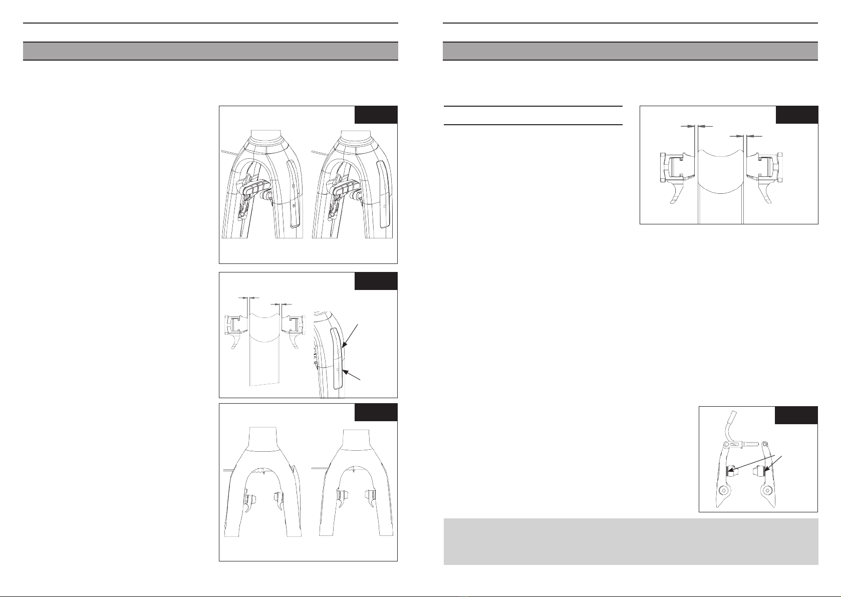
MONTAGE DES ROUES
Suivre les indications de montage du fabricant.
Nos pattes de fourche sont conçues avec des
ergots de sécurité.
Avant de rouler s’assurer que les roues sont
fortement bloquées par le mécanisme de
blocage rapide.
ENTRETIEN
Nettoyer toujours votre cadre avec du savon ou
détergent léger et de l’eau.
Employer un chiffon doux. Rincer votre cadre à
l’eau et le sécher avec un chiffon.
Ne pas utiliser d’appareil de nettoyage à haute
pression, ni de produits abrasifs.
Pour éliminer les taches de goudron, utiliser un
produit pour carrosserie de voiture.
SERVICE APRÈS-VENTE
Malgré tout le soin apporté à notre fabrication,
si un défaut apparaît ou si une réparation
est nécessaire, s’adresser toujours à votre
revendeur avec le cadre ou la fourche
accompagné(e) de la carte de garantie.
GARANTIE
Nos cadres et nos fourches sont garantis cinq
ans à partir de la date d’achat contre tout vice ou
défaut de fabrication. La peinture, la décoration,
le vernis et tout ce qui concerne la finition sont
garantis un an.
Pour que la garantie soit valable enregistrez-vous
sur notre site www.lookcycle.com
Cette garantie reste limitée à l’acheteur initial et
une preuve d’achat est requise (facture originale).
La garantie concerne les cadres pour tous vices
ou défauts de fabrication.
ATTENTION :
Inspecter toujours votre vélo avant de l’utiliser.
Si les tubes de votre cadre LOOK ou votre
fourche ont subi n’importe quel
dommage, rapporter le vélo chez votre
revendeur LOOK pour une inspection.
Prendre connaissance des lois en vigueur
dans le pays où vous êtes si vous roulez la nuit.
Les réflecteurs ne sont pas suffisants et ne
remplacent pas un éclairage.
Porter toujours un casque
Prendre connaissance du code de la route et
le respecter.
Prendre garde aux dangers de la route et de la
circulation.
La garantie s’applique uniquement si le cadre est
assemblé conformément aux
instructions ci dessus.
La garantie ne s’applique pas aux dégâts
occasionés par un mauvais entretien ou une
mauvaise utilisation.
De même la garantie est caduque si le cadre ou
la fourche a subi une modification technique du
fait de l’utilisateur ou s’il a été réparé, repeint
hors d’un centre de réparation agréé LOOK. En
particulier ne pas supprimer les ergots de sécurité
des pattes de fourche.
La garantie ne couvre pas les cas suivants :
* les dégâts causés par négligence ou entretien
insuffisant
* les accidents
* les dommages accessoires et indirects
Les dépenses de montage, démontage, temps de
main d’oeuvre, emballage et expédition du cadre
ne sont pas couverts.
Ne pas percer, peindre ou revernir.
Ne pas laisser le cadre près d’une source de
chaleur.
Fig. s