Ecotop 066GDHC2 User manual

Order N° 066GDHC2
ATTENTION !
Ce modèle à construire n’est pas un jouet, il
ne convient pas aux enfants de moins de 14 ans.
Une mauvaise utilisation de ce matériel peut
provoquer des dommages matériels ou corporels.
Vous êtes pleinement responsable
lorsque vous utilisez votre modèle.
Volez à une distance de sécurité des zones
habitées.
Soyez sûr que personne n’émet sur la même
fréquence que vous.
CAUTION !
This model construction kit is not a toy and is not
suitable for children under the age of 14.
Incorrect use of this material could cause material
damage ou personal injury.
You are fully responsible for your actions when you
use this model.
Fly at a safe distance from occupied zones.
Be sure that no one else is using the same
frequency as you.
Distribué par / Distributed by:
TOPMODEL S.A.S.
Le jardin d’entreprises de SOLOGNE - F-41300 SELLES SAINT DENIS - www.topmodel.fr
©TOPMODEL 2011
Caractéristiques techniques/Technical data:
Echelle/scale: 1:6
Envergure/wingspan: 2,44m
Longueur/length: 1,61m
Poids/TO weight: 6,5/7,2kg
Surface/wing area: 68,4dm2
Profil/airfoil: NACA
Equipements recommandés/Recommended equipments:
Moteur/motor: SAITO FA-180 ou/or XPower XC6332/16 (version électrique/electric version)
Contrôleur/ESC: XPower XREG100HV (version électrique/electric version)
Accu/battery pack: XPower Xtreme11,1V 5000mAh x3 (9S) (version électrique/electric version)
Hélice/prop: MENZ 18x8 ou APC E 18x10 (version électrique/electric version)
Cône/spinner: CONE ALU KS Ø70x70 #012707
Radio/RC set: Récepteur/receiver: FUTABA R1410DP
Ailerons: 2 servos HITEC HS-635HB
Profondeur/Elevator: 1 servo HITEC HS-635HB
Direction/Rudder: 1 servo HITEC HS-635HB
Volets/Flaps: 2 servos HITEC HS-635HB
Gaz/Throttle: 1 servo HITEC HS-311(version thermique/IC version)
Accu Rx/Rx pack: 4,8V 4600mAh #A446009S (version thermique/IC version)
Régulateur/Regulator: XPower SVR3-5V (version électrique/electric version)
Distribué par / Distributed by:
p
/
y
TOPMODEL
S.A.S.
L
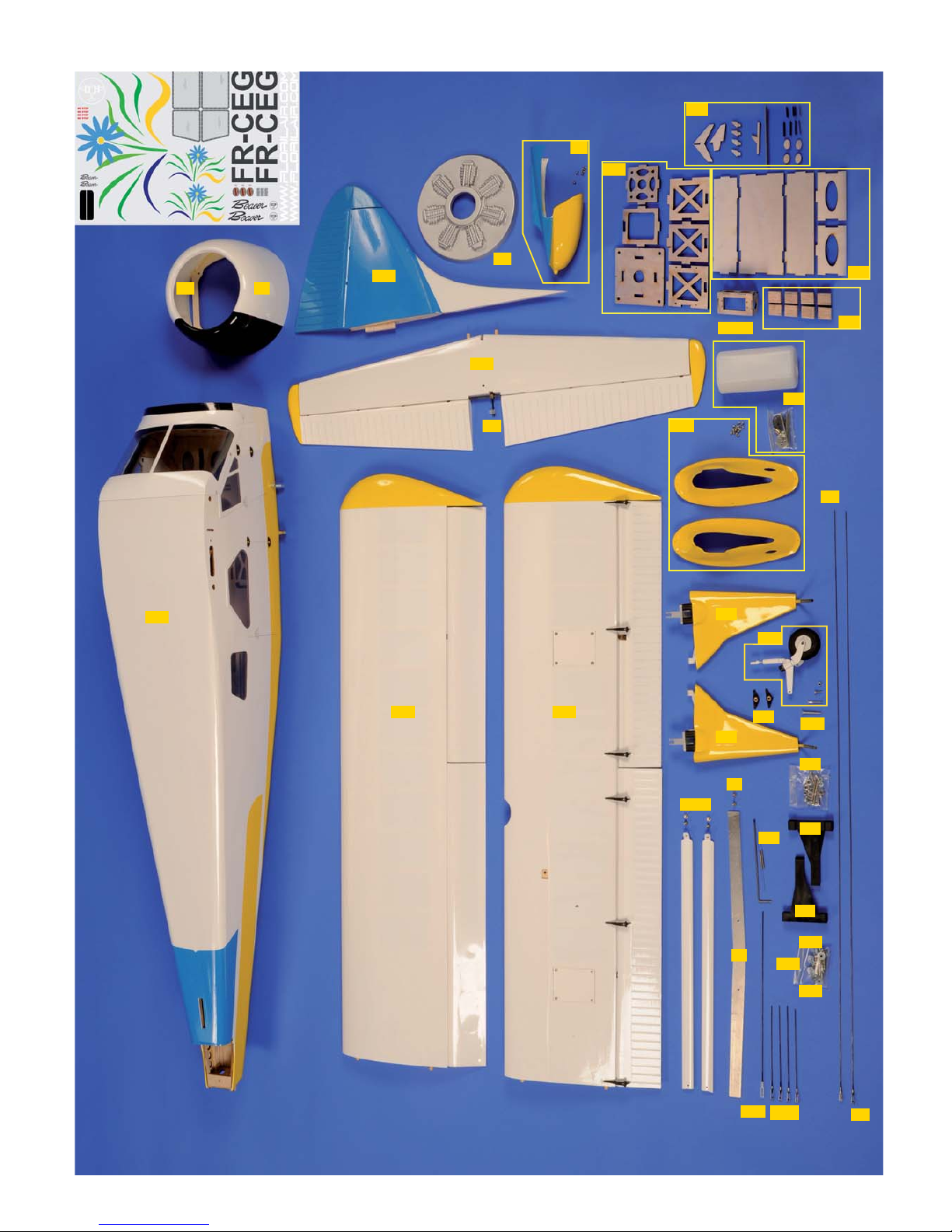
Avion semi-maquette
Semi-scale plane
DE HAVILLAND DHC-2

2
RETENDRE L’ENTOILAGE
1) Déballez doucement en prenant soin de ne pas endommager une
partie du kit. Déballez toutes les pièces de leur emballage plastique pour
inspection.
Avant de commencer tout montage ou de poser tout auto-collant, il
est très important de retendre l’entoilage déjà appliqué. A cause du
transport, de la chaleur et de l’humidité qui varient beaucoup suivant les
différents climats, l’entoilage peut se détendre et se “rider” au soleil. Si
vous prenez le temps de retendre l’entoilage, vous serez récompensé par
un modèle qui restera magnifique dans le temps.
2) En utilisant un fer à soler et un chiffon doux, “repassez” délicatement
et “suivez” en appliquant le film avec le chiffon. Si des bulles apparaissent,
votre fer est peut être trop chaud. Réduire la température et travaillez
doucement et patiemment.
3) Si les bulles persistent, piquer les bulles à l’aide d’une aiguille pour
évacuer l’air emprisonné et chauffer de nouveau.
4) Utilisez le décapeur thermique avec beaucoup de précaution. Faire
attention de ne pas chauffer au même endroit trop longtemps. Cela
pourrait trop rétracter les bords et laisser un espace découvrant le bois
aux jointures des différentes couleurs. Les filets sont particulièrement
vulnérables à la surchauffe.
5) Votre modèle est entoilé avec de l’Oracover® blanc N°10, jaune N°33
et bleu clair N°53.
MERCI
d’avoir choisi l’avion semi-maquette DHC-2 BEAVER!
Nous avons fait un grand effort en dessinant et construisant ce planeur pour qu’il soit le meilleur modèle que vous ayez jamais construit et fait voler.
Nous vous fournissons un kit avec la plus haute qualité et les meilleures performances possibles.
Nous vous souhaitons un grand succès en assemblant et en faisant évoluer votre nouveau
DHC-2 BEAVER ECOTOP.
IMPORTANT:Merci de bien vouloir lire et étudier cette notice de montage avant de commencer l’assemblage. Faire l’inventaire des pièces à l’aide de la nomenclature
pour contrôler qu’il n’y a pas de manquant ou d’imperfection.
Merci de contacter immédiatement TOPMODEL si vous constatez une pièce manquante ou une pièce endommagée.
GARANTIE: Il est important de notifier à TOPMODEL tous dommages ou problèmes avec ce modèle dans les 7 jours suivant la réception du kit pour bénéficier de la
garantie. En cas de retour du modèle, le client est responsable du transport et le port retour est à sa charge. En cas de défaut, la pièce sera échangée ou remplacée une
fois que celle-ci sera réceptionnée par TOPMODEL pour expertise (transport à la charge du propriétaire). En cas de problème, n’hésitez pas à contacter TOPMODEL.
TOPMODEL ne peut pas contrôler la dextérité du modéliste et ne peut pas influencer le constructeur durant l’assemblage ou l’utilisation de ce modèle radio-commandé.
Aussi, nous ne pouvons, en aucun cas, être tenus responsables des dégâts matériels, accidents corporels ou décès pouvant être causés par ce modèle réduit.
L’acheteur/utilisateur accepte toutes les responsabilités en cas de problèmes structurels ou mécaniques.
POUR ASSEMBLER CE KIT
Pour assembler ce kit, vous aurez besoin des produits énumérés ci-dessous:
■ COLLES: Cyano fluide et épaisse, époxy 30mn et 5mn, colle silicone.
■ OUTILS: Couteau de modéliste, tournevis cruciforme (petit et moyen), pince à bec fin, pince coupante, ciseaux, ruban adhésif, ruban adhésif de
masquage, ruban adhésif double-faces, perçeuse (foret Ø0,6-1,8-3 et 3,5mm), papier verre, règle, feutre, clips, alcool, fer à souder, chiffon.

3
RE-SHRINKING THE COVERING
1) Open you kit slowly and take care not to damage any parts of the kit.
Remove all parts from their plastic protective bags for inspection. Before
doing any assembly or installation of any decals, it is very important to
re-shrink or re-tighten the already applied covering. Due to the shipping
process, heat and humidity changes from different climates, the covering
may become lose and wrinkle in the sun. If you take the time to re-tighten
the covering, you’ll be rewarded with a long lasting beautifully covered
model.
2) Using your covering iron with a soft sock, gently apply pressure and rub
in the covering. If any bubbles occur, your iron may be too hot.
Reduce heat and work slowly.
3) If bubbles persist, use a small pin to punch holes in the bubble to
relieve trapped air and reheat.
4) Use your heat gun with extreme caution. Take care not to apply too
much heat to one area for long periods of time. This may cause the trim
colors to over shrink and pull away leaving sightly gaps on the color lines.
The trim stripes are especially vulnerable to over shrinking.
5) Your model is covered with Oracover® white #10, cadnium yellow #33
and sky blue #53.
THANK YOU for your purchase of the ECOTOP semi-scale ARF plane
DHC-2 BEAVER
!
We made a main effort while drawing and building this sailplane so that it is the best model one than you ever built and fly.
We provide you a kit with the highest quality and the best possible performances.
We wish you a great success while assembling and flying your new
DHC-2 BEAVER ECOTOP
.
IMPORTANT: Please take a few moments to read this instruction manual before beginning assembly. Do an inventory of the parts using the parts list, to control that
there is no lack or imperfection. Thank you to contact TOPMODEL immediately, if you note a missing part or a damaged part.
WARRANTY: It is important to notify to TOPMODEL all damage or problems with this model within 7 days following the reception of the kit to be able to benefit the
warranty. In the event of return of the model, the customer is responsible for transport and return shipping cost is at his expenses. In the event of defect, the part will be
exchanged or replaced once this one will be delivered to TOPMODEL for expertise (transport on your cost). In the event of problem, do not hesitate to contact TOPMODEL.
TOPMODEL cannot control the dexterity of the modeler and cannot influence the builder during the assembly or the use of this radiocontrolled model, thus TOPMODEL will in
no way accept or assume responsability or liability for damages resulting from the use of this user assembled product.
The purchaser/user accepts all the responsibilities in the event of structural or mechanical problems.
TO ASSEMBLE THIS KIT
To assemble this kit, you’ll need the items listed below:
■ ADHESIVE: Cyanoacrylate thin and thick, epoxy 30’ and 5’ adhesives, silicon adhesive.
■ TOOLS: Knife (X-acto), Phillips screw driver (small and medium), needle tip pliers, pliers, scissors, scotch tape, masking tape, double sticking
tape, drill (with 0,6-1,8-3 and 3,5mm bits), sanding paper, ruler, ball point pen, clips, alcohol, soldering iron, piece of cloth or rags.
3
2 2 3-2
2-1
4
4-8
4-8
3-8
2-4
1-7
SS
4-5
24
24
99-0
9T
1R
1BR
9-21
9-21S
3-5
2-5
1
1-1
10-2
8-3
2-2
1-1
1-1
1-3
10M
10-3
10
10
5
CONTENU DU KIT KIT CONTENT
N° pièce Désignation Matériau, dimensions (mm) Qté
0 notice de montage manuel A4 01
1 fuselage structure entoilée 01
1-1 bâti moteur thermique ajustable nylon+set visserie 02+01
1-3 réservoir 450cc 01 set
1-7 boîtier accu propulsion CTP 3mm 01 set
1BR bâti moteur électrique CTP 5mm 01 set
1R pointe arrière fuselage fibre de verre moulée, peinte+vis à bois 2x6 01+06
2 aile structure entoilée 02
2-1 hauban d’aile alu+vis M3x10 02+04
2-2 fixation ailes vis M4x15 02
2-4 fixation servos aile taquet bois dur 08
2-5 tringlerie aileron+volet CAP filetée un bout M2+chape 04+04
24 clé d’aile alu+vis M3x15 01+02
3 empennage horizontal structure entoilée 01
3-2 fixation stab. vis M4x30 01
3-5 tringlerie de profondeur CAP filetée un bout M2+chape 01+01
3-8 guignol de profondeur vis Chc M3x30+guignol plastique 01+01
4 empennage vertical structure entoilée 01
4-5 tringlerie direction CAP filetée un bout M2+chape 01+01
4-8 guignol de direction barre de torsion Ø3+bras de commande+ressort 01+02+02
7 décoration autocollants 01 set
8-3 fixation roue bague d’arrêt 04
9 capot moteur fibre de verre, moulé, peint 01
9-0 fixation capot vis Chc M3x15 04
9-21 commande des gaz CAP filetée un bout M2+chape plastique 01+01
9-21S support servo gaz CTP 3mm 01 set
9T faux moteur plastique 01
10 train d’atterrissage amorti 01 set
10-2 fixation train vis M4x40+M4x25+M3x15+écrou 02+02+02+06
10-3 roulette de queue amortie+roue Ø55+vis M3x10+M3x20+écrou 01+01+01+01+01
10M raccord train fibre de verre, moulé, peint+vis à bois 2x6 02+16
SS Scale Set CTP 01 set
Part # Item Material, dimensions (mm) Qty
0 building instructions A4 booklet 01
1 fuselage all built-up, covered 01
1-1 engine mount nylon ajustable+screws set 02+01
1-3 tank 450cc 01 set
1-7 battery packs box plywood 3mm 01 set
1BR motor mount plywood 5mm 01 set
1R fuselage rear cone molded fiberglass, painted+2x6 self tapping screw 01+06
2 wing all built-up, covered 02
2-1 wing brace alu+screw M3x10 02+04
2-2 wing fixing screw M4x15 02
2-4 wing servos fixing hard wood block 08
2-5 aileron+flap linkage music wire threaded one end M2+clevis 04+04
24 wing joiner alu+screw M3x15 01+02
3 horizontal tail all built-up, covered 01
3-2 horizontal tail fixing screw M4x30 01
3-5 elevator linkage music wire threaded one end M2+clevis 01+01
3-8 elevator horn M3x30 Chc screw+plastic horn 01+01
4 rudder all built-up, covered 01
4-5 rudder linkage music wire threaded one end M2+clevis 01+01
4-8 rudder horn Ø3 torsion bar+steering arm+spring 01+02+02
7 art work stickers 01 set
8-3 wheel fixing wheel collar 04
9 engine cowl molded fiberglass, painted 01
9-0 engine cowl fixing M3x15 Chc screw 04
9-21 throttle linkage music wire threaded one end M2+plastic clevis 01+01
9-21S throttle servo tray plywood 3mm 01 set
9T dummy engine plastic 01
10 landing gear dampened 01 set
10-2 landing gear fixing screw M4x40+M4x25+M3x15+nut 02+02+02+06
10-3 tailwheel dampened+Ø55 wheel+screw M3x10+M3x20+nut 01+01+01+01+01
10M gear fairing molded fiberglass, painted+2x6 self tapping screw 02+16
SS Scale Set plywood 01 set
5
DE HAVILLAND DHC-2

6
1) Dévisser et retourner la trappe d’accès au servo d’aileron.
Unscrew and turn over the aileron servo hatch.
2) Trappe en place à l’envers, tracer l’axe du guignol d’aileron sur le
CTP de la trappe.
On upside down hatch, draw the axis line of the
aileron control horn.
3) Visser le servo sur les taquets en bois dur 2-4. Coller les taquets
sur la trappe avec de la colle époxy 5mn, le palonnier au ras du trait
précédemment tracé (voir photo).
Screw in the servo on hard wood blocks 2-4. Then
glue the blocks to the hatch with 5’ epoxy glue;
the servo horn flush to the line you just draw (see
photo).
4) Connecter une rallonge de 700mm, sécuriser la connection (sécurité
de connecteur #0434085, non fournie), mettre le servo au neutre
avec le SERVO TESTER.
Connect a 700mm servo extension and secure
with safety lock #0434085 (not furnished), put
the servo in neutral position with SERVO TESTER.
INSTALLATION TRINGLERIE AILERONS/ AILERONS LINKAGE INSTALLATION
2
2-4
2-4
Axe guignol aileron
Aileron horn axis

7
5) Passer la rallonge dans l’aile à l’aide du fil déjà passé à la construc-
tion.
Pull the servo extension through the wing with
string already routed into the wing.
6) Connecter la tringlerie d’aileron 2-5 sur le guignol par la chape.
Connect 2-5 pushrod to the horn with clevis.
7) Mettre la gouverne au neutre.
Positionner le servo, repérer l’emplacement de la baïonnette à réaliser
avec un crayon gras.
Fix aileron at neutral position.
Try fit the servo, locate Z-bend to be done with a
soft lead pencil.
8) Baïonnette faite.
Z-bend completed.
INSTALLATION TRINGLERIE AILERONS/ AILERONS LINKAGE INSTALLATION
2-5
2-5

8
9) Insérer la baïonnette dans le palonnier.
Connect servo to Z-bend.
10) Revisser la trappe du servo d’aileron.
Screw in back the aileron hatch.
1) Même opération pour le servo de volet.
Dévisser la trappe, la retourner. Tracer l’axe du guignol du volet.
Same procedure for the flap servo.
Unscrew and turn over the hatch. On upside down
hatch, draw the axis line of the flap control horn
2) Coller les blocs 2-4 du servo de volet de la même manière que celui
d’aileron.
Glue the flap servo mounts 2-4 in the same way as
aileron.
INSTALLATION TRINGLERIE VOLETS/ FLAPS LINKAGE INSTALLATION
2
2-4
2-4

9
3) Mettre le servo au neutre.
Put servo at neutral position.
3) Connecter la tringlerie de volet 2-5. Faire déboucher le fil du servo
de volet à l’emplanture.
Connect flap pushrod 2-5. Pass servo cord through
the wing, exit to the root
4) Positionner le volet en position sorti 1er cran à 20 mm du neutre.
Open the flap 1st position, down 20mm.
5) Repérer la position de la baïonnette à faire au crayon gras.
Try fit the servo, locate Z-bend to be done with a
soft lead pencil.
INSTALLATION TRINGLERIE VOLETS/ FLAPS LINKAGE INSTALLATION
2-5
10
6) Réaliser la baïonnette.
Perform Z-bend.
7) Connecter la tringlerie au servo de volet.
Connect the pushrod to flap servo.
8) Revisser la trappe du servo de volet.
Screw in flap servo hatch.
Vérifier le bon fonctionnement des volets:
Check proper function of the flaps:
Vue des 3 positions (rentrés , 1er cran, plein volet)
View of the 3 different positions:
closed, 1st position, full flaps.
INSTALLATION TRINGLERIE VOLETS/ FLAPS LINKAGE INSTALLATION
2-5
2

11
1) Visser la jambe de train 10 en position comme sur la photo.
Screw in landing gear 10 in position as shown.
2) Enfiler le carénage 10M sur la jambe de train et le visser au fuselage
à l’aide des vis 2x6 mm fournies.
Slip on the leg of the gear fairing 10M and screw it
to the fuselage using 2x6 mm self tapping screws
provided.
3) Faire un méplat à la lime à l’endroit des butées de roue 8-3. Monter
les roues (non fournies).
With a file, do a flat on axle where the wheel col-
lars 8-3 applied. Mount the wheels (not provided).
INSTALLATION TRAIN PRINCIPAL/ MAIN GEAR INSTALLATION
10
1
10
8-3
10M
1
12
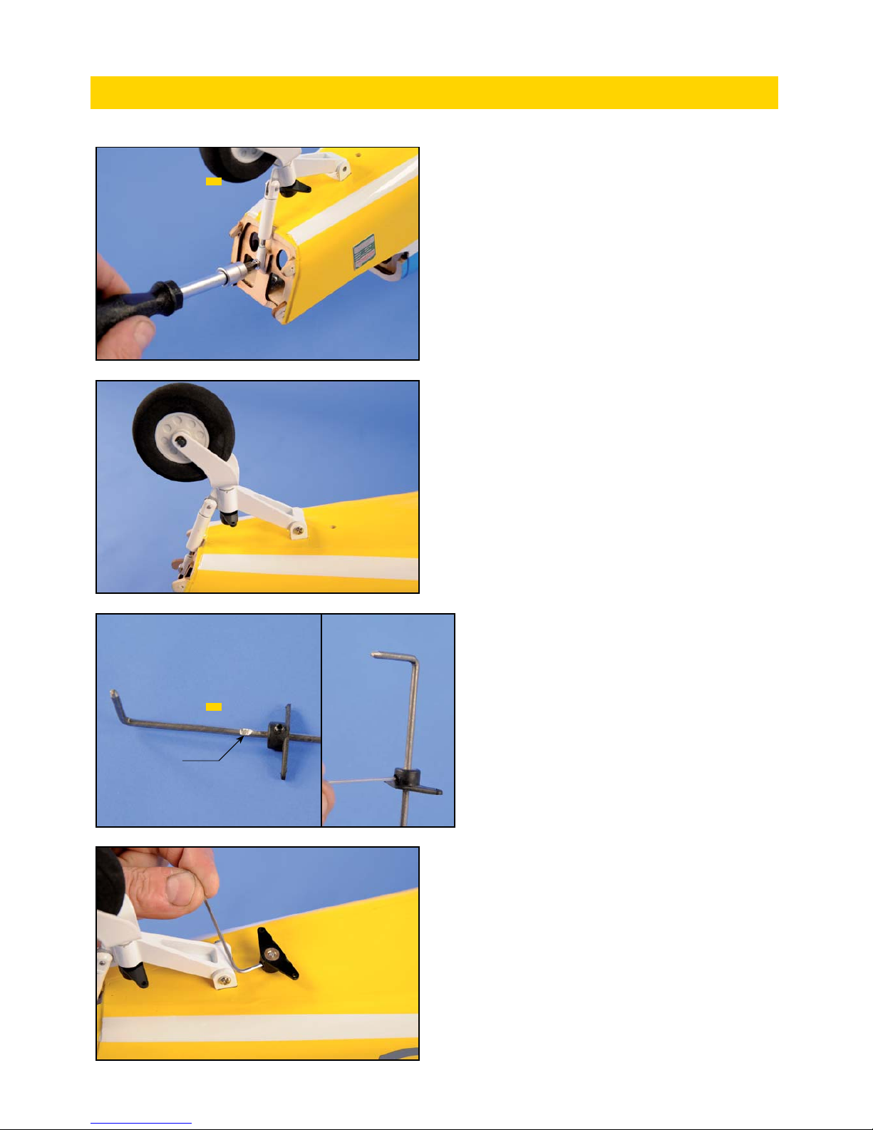
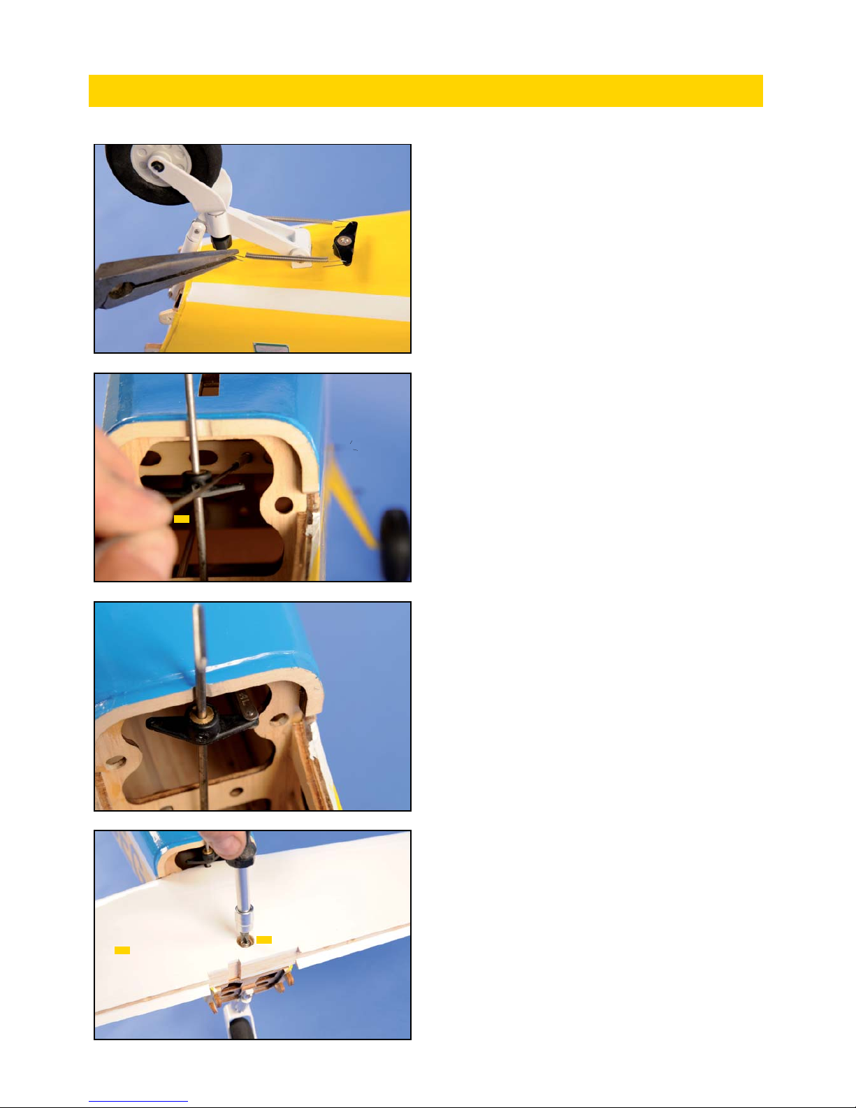
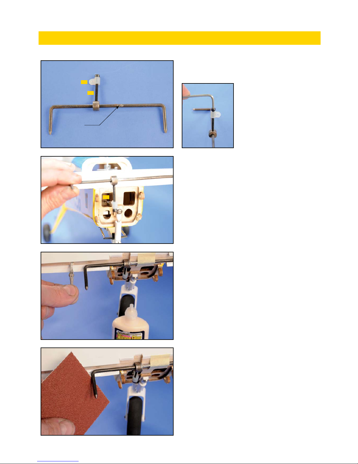
1) Monter la roulette de queue 10-3. Assurer le serrage de la vis
arrière avec du frein filet.
Install tailwheel 10-3. Use thread lock.
3) Passer la commande de direction dans le fuselage et monter le bras
de commande de la roulette comme montré.
Insert rudder linkage into the fuselage and install
tailwheel steering arm as shown.
INSTALLATION ROULETTE DE QUEUE/ TAILWHEEL INSTALLATION
Méplat/Flat
10-3
4-8
2) Insérer le bras de commande de direction 4-8 sur la barre
de torsion. Serrer le bras à l’endroit du méplat deja réalisé en
usine.
Slip on torsion bar rudder arm 4-8. Tigh up
the arm where is the flat already made at
the factory.
13
4) Ajuster la longueur des ressorts et relier les bras de commande.
Adjust the length of springs and connect them to
the steering arms.
5) Insérer la tringlerie de direction 4-5 dans sa gaine.
Insert rudder linkage 4-5 into outer tube already
installed in the fuse.
6) Connecter la chape au bras de commande.
Connect clevis to rudder arm.
7) Monter le stabilisateur 3 (tétons à l’avant vis 3-2 à l’arrière).
Instal H. stab.3 (dowels at the front, screw 3-2 at
the rear).
INSTALLATION EMPENNAGE HORIZONTAL/ HOR TAIL INSTALLATION
4-5
3
3-2
14
8) Visser la vis avec son guignol 3-8 sur la barre de jonction des 1/2
profondeur comme montré (la bague peut être soudée sur la CAP pour
plus de sécurité). De même que pour la direction, un méplat est déjà
réalisé afin de positionner la bague.
9) Enfiler la tringlerie de profondeur 3-5 dans sa gaine et connecter la
chape sur le guignol.
Insert elevator linkage 3-5 into outer tube already
installed in the fuse and connect the clevis to the
horn.
10) Coller les charnières dans le plan fixe de la profondeur....
Glue pin hinges into H. stab...
....dépolir l’extrémités de la barre de jonction des 1/2 profondeur et...
Scratch with sanding paper the ends of elevator
joiner and...
INSTALLATION EMPENNAGE HORIZONTAL/ HOR TAIL INSTALLATION
Méplat/Flat
3-8
3-8
3-5
Screw in 3-8 with its horn,
on to the elevator coupler
as shown (the collar can be
welded on the music wire
for more safety). A flat is
already done to be able to
locate the collar.

15
...les enduire de colle époxy et dans la foulée...
...coat them with epoxy glue and immediately...
...coller les charniéres dans les 2 volets de profondeur. Vérifier le
fonctionnement.
...glue the pin hinges into elevators. Check free
movement.
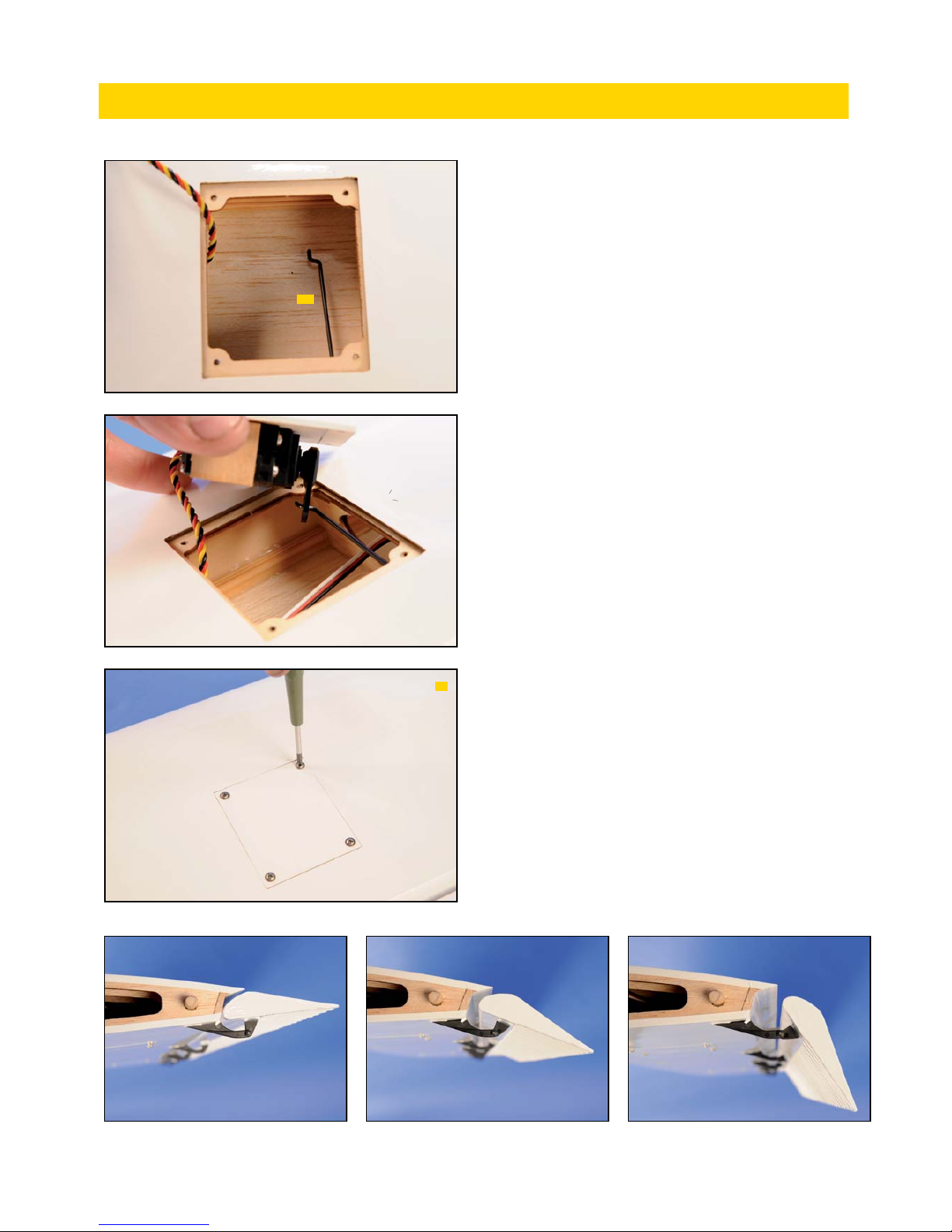
1) Positionner l’empennage vertical 4 sur le fuselage.
Trail fit vertical tail 4 on the fuselage.
2) Tracer son contour.
Draw its outline shape.
INSTALLATION EMPENNAGE HORIZONTAL/ HOR TAIL INSTALLATION
4

16
3) Découper soigneusement l’entoilage légèrement en retrait du tracé.
Carefully cut out the covering inside the line.
4) Coller l’empennage vertical 4 à l’époxy. Essuyer le surplus.
Glue vertical tail 4 with epoxy glue. Wipe clean
with a piece of cloth.
5) Vérifier la géométrie avant que la colle ne soit sèche.
Check the geometry before adhesive is dry.
6) Coller les charnières dans le volet de dérive.
Glue pin hinges inside the rudder.
INSTALLATION EMPENNAGE VERTICAL/ VERTICAL TAIL INSTALLATION
1
1
4

17
7) Dépolir l’extrémité de la commande de direction 4-8 et l’enduire de
colle époxy.
Scratch with sanding paper the end of rudder lin-
kage 4-8 and coat with epoxy adhesive.
8) Coller le volet de dérive. Vérifier le fonctionnement.
Glue rudder. Check free movement.
9) Monter le carénage 1R à l’extrémité du fuselage à l’aide des vis
2x6mm fournies.
Install fuselage rear cone with 2x6mm self tap-
ping screws provided.
INSTALLATION EMPENNAGE VERTICAL/ VERTICAL TAIL INSTALLATION
1R
4-8
1R

18
1) Monter les servos de profondeur et direction.
Install elevator and rudder servos.
2) Positionner les gouvernes au neutre et mettre les servos au neutre
à l’aide du SERVO TESTER.
Maintain control surfaces in neutral position and
put servos in neutral position with SERVO TES-
TER.
3) Repérer la longueur des tringleries.
Locate linkages proper lenght.
4) Réaliser une baïonnette sur chaque CAP et les connecter au palon-
nier.
Perform Z-bend on each linkage and connect to
servo arm.
5) Remonter la trappe.
Screw in hatch.
1) Visser le moteur thermique sur son bati 1-1.
La cote entre le plateau d’hélice et la base du bati est de 165mm.
Install IC engine on its mount 1-1.
Dimension between prop driver and firewall is
165mm.
INSTALLATION DIRECTION-PROFONDEUR/ RUDDER-ELEVATOR INSTALLATION
1-1
1
165mm

19
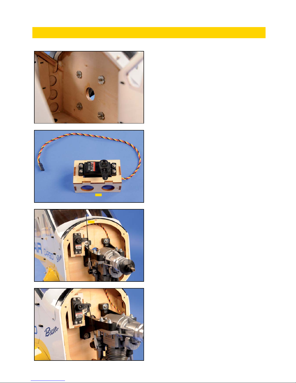
2) Positionner le moteur sur son bâti sur la cloison pare-feu et tracer
l’emplacement des vis de fixation.
Locate engine mount on firewall and draw fixing
screws location.
3) Percer aux emplacements repérés.
Drill where located.
4) Réunir moteur et vis de fixation.
Gathered engine and fixing screws.
5) Monter le moteur sur le fuselage.
Install the engine on the fuselage.
INSTALLATION MOTEUR THERMIQUE/ IC ENGINE INSTALLATION
20
6) Les écrous à griffes peuvent être collés à l’époxy, les vis assurées
avec du frein filet.
The blind nuts can be glued to the epoxy, screws
secured with thread lock.
7) Monter le servo de gaz sur son support 9-21S.
Install throttle servo on its mount 9-21S.
8) Le présenter sur la cloison pare-feu, tringlerie de gaz 9-21 connec-
tée sur le carburateur du moteur.
Trial fit on firewall, throttle linkage 9-21 connec-
ted on the carburateur of the engine.
9) Repérer la meilleure position, coller le support servo sur la cloison à
l’époxy. Ajuster la tringlerie et la connecter au servo.
Locate the best position, glue the mount to the fi-
rewall with epoxy adhesive. Adjust linkage length
and Z-bend to the servo arm.
INSTALLATION MOTEUR THERMIQUE/ IC ENGINE INSTALLATION
9-21S
9-21
Table of contents
Other Ecotop Toy manuals

Ecotop
Ecotop Spacewalker I 06604 User manual

Ecotop
Ecotop ARS 300 User manual

Ecotop
Ecotop PILATUS B4 User manual

Ecotop
Ecotop Schleicher Scale Series User manual

Ecotop
Ecotop Schleicher Ka-8b User manual

Ecotop
Ecotop PILATUS PC-6 TURBO PORTER User manual

Ecotop
Ecotop Schleicher Ka-8b User manual

Ecotop
Ecotop BIDULE 55 User manual
Popular Toy manuals by other brands


V-tech
V-tech Switch & Go Velociraptor Motorcycle instruction manual

InVento
InVento 500820-3318 instruction manual

LaserPegs
LaserPegs Dragster Truck PB 1430B Model instructions

V-tech
V-tech Winnie the Pooh Explore n Learn Table user manual

Little Tikes
Little Tikes Glow'n Speak Animal Flashlight manual

Hornby
Hornby B17 CLASS Operating and maintenance instructions


