Ecotop PILATUS PC-6 TURBO PORTER User manual
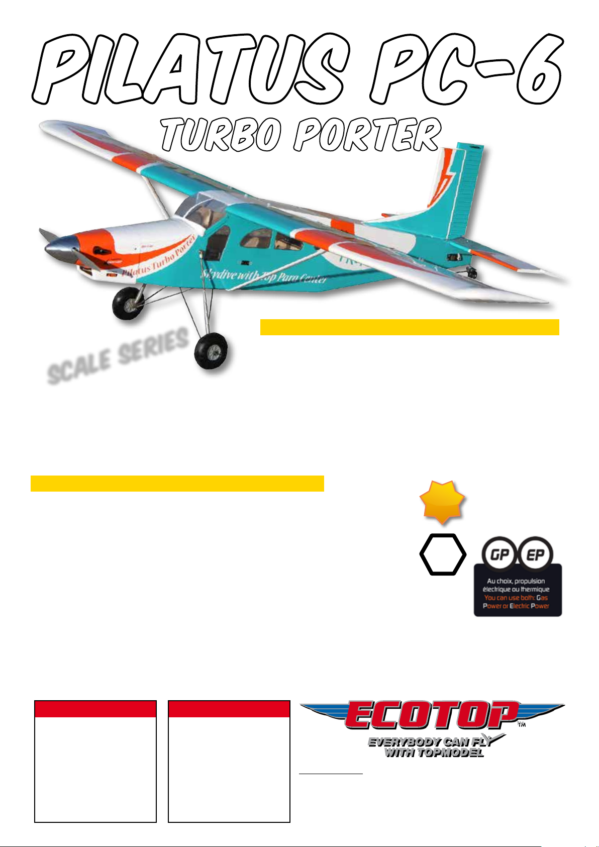
PILATUS PC-6
TURBO PORTER
ATTENTION ! CAUTION !
Distribué par / Distributed by:
TOPMODEL S.A.S.
Le jardin d’entreprises de SOLOGNE - F-41300 SELLES SAINT DENIS
www.topmodel.fr
©TOPMODEL 2014
Ce modèle à construire n’est pas un jouet, il
ne convient pas aux enfants de moins de
14 ans.
Une mauvaise utilisation de ce matériel peut
provoquer des dommages matériels
ou corporels. Vous êtes pleinement
responsable
lorsque vous utilisez votre modèle.
Volez à une distance de sécurité des zones
habitées.
Soyez sûr que personne n’émet sur la même
fréquence que vous.
This model construction kit is not a toy and is
not suitable for children under the age of 14.
Incorrect use of this material could cause
material damage ou personal injury.
You are fully responsible for your actions
when you use this model.
Fly at a safe distance from occupied zones.
Be sure that no one else is using the same
frequency as you.
Equipements recommandés / Related items :
Pour moteur thermique / For Gas Power (GP):
Moteur / Engine : 2 temps (2C) 10 cc (OS 65 AX) / 4 temps (4C) 13,5 cc (Saito FA-82B)
Hélice / Propeller : 13 x 6" (OS 65 AX), 14 x 6" (Saito FA-82B)
Pour motorisation électrique / For Electro Power (EP) :
Moteur / Motor : XPower XC5025/16 (# 099C502516)
Contrôleur / ESC : XPower XREG60 (# 099REG60)
Accu / Battery pack : 2 x LiPo HOT LIPS 11,1 V 4000 mAh 3S1P PK (#09140003S1P40)
Hélice / Propeller : APC-E 14 x 7" (# 017E147)
Radio / RC set: Récepteur/Receiver : JETI DUPLEX R8 EX
Ailerons : 2 servos TOPMODEL S3217
Profondeur/Elevator : 1 servo TOPMODEL S3217
Direction/Rudder : 1 servo TOPMODEL S3217
Volets/Flaps : 2 servos TOPMODEL S3217
Gaz/Throttle : 1 servo TOPMODEL S3217 (glow/GP version)
Accu Rx / Rx Battery : NiMh 4,8 V 3600 mAh (# A436109S)
Divers: Voir liste page 8 / See the list page 8.
Caractéristiques techniques / Technical data :
Envergure / wingspan : 2,07 m
Longueur / length : 1,55 m (environ / approximately)
Poids / TO weight : 4,5 - 4,7 kg
Surface / wing area : 54 dm
2
Prol / airfoil : NACA 2415 Mod.
Avion semi-maquette thermique ou électrique
Semi-scale airplane for gas power or electric power
Order N° 066GPC613
ARF
Scale series
TRA
Idéal comme 2ème
ou 3ème modèle
Ideal as 2nd
or 3rd model

Notice Ecotop - Page 2 - Pilatus PC-6 Turbo Porter 2.07m ARF
MERCI d’avoir choisi notre semi-maquette de Pilatus PC-6 Turbo Porter ARF!
Nous avons fait un grand effort en dessinant et construisant cet avion pour qu’il soit le meilleur modèle que vous ayez jamais construit
et fait voler. Nous vous fournissons un kit avec la plus haute qualité et les meilleures performances possibles.
Nous vous souhaitons un grand succès en assemblant et en faisant évoluer votre nouveau Pilatus PC-6 Turbo Porter ARF.
Souvent surnommé la "Jeep des airs", le Pilatus PC-6 a volé pour la première fois en 1959 et les premières séries étaient équipées
de moteurs à pistons. La cellule robuste sera ensuite équipée de turbopropulseurs, d'abord le Turboméca Astazou de 523 CV, puis
pour la version la plus connue, le Pratt & Whitney PT6A de 650 ou 750 CV. Cet avion utilitaire est surtout connu comme avion largeur
de parachutistes, pouvant emporter 9 à 10 sauteurs à 4 000 m en 15 minutes et capable d'en redescendre en 3 minutes. Il a été utilisé
dans une grande variété d'utilisations, cargo, avion de transport STOL, bombardier d'eau ou gunship.
Le modèle offre comme l'original de belles capacités de décollage et atterrissage courts, est particulièrement maniable et facile à
piloter, son comportement étant celui d'un grand trainer. Le train suspendu, y compris au niveau de la roulette de queue, et doté de
roues de fort diamètre, permet l'utilisation de pistes en herbe grossières.
Pour la troisième version de ce kit, nous avons optimisé le fuselage pour qu'il soit aussi facile d'y installer une motorisation thermique
qu'un ensemble de propulsion électrique. Une trappe sur le nez facilite l'accès au réservoir ou à l'accu de propulsion.
Les points forts du Pilatus PC-6 Turbo Porter
●L'allure et le style de vol du Turbo Porter original sont respectés.
●L'entoilage en Oracover robuste et facile à réparer en cas de besoin.
●Le vol est aussi facile que celui d'un gros trainer.
●Les très grandes roues et le train suspendu qui facilite l'utilisation sur piste en herbe.
●Et bien sûr… le modèle est livré monté et entoilé, il ne vous reste plus que l’assemblage nal, le montage de la radio et de la
motorisation à réaliser.
Le Pilatus décolle et se pose court, peut voler assez vite, mais est également très agréable aux basses vitesses grâce à ses volets.
Il est capable de passer la voltige de base.
Informations additionnelles:
●Vous pouvez choisir une motorisation électrique ou thermique, le comportement ne change pas.
●En électrique, l'accu 6S 4 000 mAh assure des vols de 10 à 12 minutes, et il est possible de monter 6S 5 000 mAh pour des vols
plus longs.
●Le prol biconvexe dissymétrique très porteur, associé à une charge alaire modérée et à des volets efcaces, assure des atterrissages
à vitesse réduite.
IMPORTANT:
Merci de bien vouloir lire et étudier cette notice de montage avant de commencer l’assemblage. Faire l’inventaire des pièces à l’aide
de la nomenclature, pour contrôler qu’il n’y a pas d’élément manquant ou d’imperfection.
Merci de contacter immédiatement TOPMODEL si vous constatez une pièce manquante ou une pièce endommagée.
GARANTIE:
Il est important de notier à TOPMODEL tous dommages ou problèmes avec ce modèle dans les 7 jours suivant la réception du kit
pour bénécier de la garantie. En cas de retour du modèle, le client est responsable du transport et le port retour est à sa charge. En
cas de défaut, la pièce sera échangée ou remplacée une fois que celle-ci sera réceptionnée par TOPMODEL pour expertise (transport
à la charge du propriétaire). En cas de problème, n’hésitez pas à contacter TOPMODEL.
TOPMODEL ne peut pas contrôler la dextérité du modéliste et ne peut pas inuencer le constructeur durant l’assemblage ou l’utilisation
de ce modèle radiocommandé. Aussi, nous ne pouvons, en aucun cas, être tenus responsables des dégâts matériels, accidents
corporels ou décès pouvant être causés par ce modèle réduit.
L’acheteur/utilisateur accepte toutes les responsabilités en cas de problèmes
structurels ou mécaniques.

Notice Ecotop - Page 3 - Pilatus PC-6 Turbo Porter 2.07m ARF
THANK YOU for your purchase of our semi-scale aircraft Pilatus PC-6 Turbo Porter ARF !
We made a main effort while drawing and building this plane so that it is the best model you ever built and y. We provide you a kit
with the highest quality and the best possible performances.
We wish you a great success while assembling and ying your new Pilatus PC-6 Turbo Porter ARF.
Often called the "Flying Jeep", the Pilatus PC-6 ew for the rst time in 1959 and the early series were equipped with piston engines.
His rugged airframe will be later equipped with turboprop engines, initially with Turboméca Astazou 523 HP and then, on the most
famous version, with a Pratt & Whitney PT6A delivering 650 or 750 HP. This utility aircraft is best known for his use by skydiving
centers, were it may take 9-10 jumpers to 4000 m within 15 minutes and is able to be back to ground within 3 minutes only. It has been
used for a wide range of uses, cargo, STOL transport aircraft, water bomber or gunship .
The model offers the same capacity of short takeoffs and landings and is particularly handy and easy to y. It ies like a big trainer.
The damped landing gear and tail wheel, tted with wheels of large diameter, allows the use of rugged grass strips.
For this third version of the kit, we optimized the fuselage to make it easy to install either a gas engine or an electric motor. A hatch on
the nose provides easy access to the tank or to the battery packs.
PC-6 Turbo Porter ARF key features
●Look and ying style of the genuine Turbo Porter are preserved.
●The Turbo Porter ARF is covered with robust Oracover lm, easy to repair if needed.
●Flying is easy, the Turbo Porter is a big trainer !
●Very large wheels and dampened landing gear make take off and landing easy on rugged grass eld.
●And of course… the model is delivered fully assembled and covered, you just have to make nal assembly, install the radio system
and the motor.
The Turbo Porter ARF is a STOL aircraft, it may y quite fast, but can also y slowly thanks to the efcient aps. It is also capable of
basic aerobatics.
Additional informations:
●You can choose to y with glow engine or with electric power.
●If you choose electric power, the 6S 4000 mAh Lipo battery pack give a ight time of 10-12 minutes. To increase ight time, you
also can use 6S 5000 mAh batteries.
●The semi-symetrical airfoil, the light wing loading, and efcient aps make landing at low speed easy.
IMPORTANT:
Please take a few moments to read this instruction manual before beginning assembly. Do an inventory of the parts using the parts
list, to control that there is no lack or imperfection.
Thank you to contact TOPMODEL immediately, if you note a missing part or a damaged part.
WARRANTY:
It is important to notify to TOPMODEL all damage or problems with this model within 7 days following the reception of the kit to be able
to benet the warranty. In the event of return of the model, the customer is responsible for transport and return shipping cost is at his
expenses. In the event of defect, the part will be exchanged or replaced once this one will be delivered to TOPMODEL for expertise
(transport on your cost). In the event of problem, do not hesitate to contact TOPMODEL.
TOPMODEL cannot control the dexterity of the modeller and cannot inuence the builder during the assembly or the use of this radio-
controlled model, thus TOPMODEL will in no way accept or assume responsibility or liability for damages resulting from the use of this
user assembled product.
The purchaser/user accepts all the responsibilities in the event of structural or
mechanical problems.

Notice Ecotop - Page 4 - Pilatus PC-6 Turbo Porter 2.07m ARF
1) Déballez doucement en prenant soin de ne pas endommager
une partie du kit. Déballez toutes les pièces de leur emballage
plastique pour inspection. Avant de commencer tout montage
ou de poser tout autocollant, il est très important de retendre
l’entoilage déjà appliqué. Votre PC-6 est entoilé avec de
l’Oracover®. A cause du transport, de la chaleur et de l’humidité
qui varient beaucoup suivant les différents climats, l’entoilage
peut se détendre et se “rider” au soleil. Si vous prenez le temps
de retendre l’entoilage, vous serez récompensé par un modèle
qui restera magnique dans le temps.
2. En utilisant un fer à entoiler et un chiffon doux, “repassez”
délicatement et “suivez” en appliquant le lm avec le chiffon.
Si des bulles apparaissent, votre fer est peut-être trop chaud.
Réduire la température et travaillez doucement et patiemment.
3. Si les bulles persistent, piquer les bulles à l’aide d’une aiguille
pour évacuer l’air emprisonné et chauffer de nouveau.
4) Utilisez le décapeur thermique avec beaucoup de précaution.
Faites attention de ne pas chauffer au même endroit trop
longtemps. Cela pourrait trop rétracter les bords et laisser
un espace découvrant le bois aux jointures des différentes
couleurs. Les lets sont particulièrement vulnérables à la
surchauffe.
Votre Pilatus PC-6 Turbo Porter ARF Ecotop est entoilé avec de l'Oracover® Blanc N° 01621-10, Turquoise N°
01621-17 et Orange N° 01621-60.
RETENDRE L’ENTOILAGE
Pour assembler ce kit, vous aurez besoin des produits énumérés ci-dessous :
●COLLES: Cyano uide et mi-uide, époxy 30 minutes et 5 minutes.
●OUTILS: Couteau de modéliste, tournevis cruciforme (petit et moyen), pince à bec n, pince coupante, ciseaux, ruban adhésif, ruban
adhésif de masquage, ruban adhésif double-faces, perceuse (foret tous diamètres), papier de verre, règle, feutre, alcool, fer à souder, chiffon, etc.
POUR ASSEMBLER CE KIT
RAPPEL
Nous prenons grand soin à fournir la meilleure qualité possible.
Toutefois, nous vous rappelons que ce ne sont pas des modèles prêts à voler et que la part du travail restante vous
incombant est très importante pour rendre le modèle apte au vol. Pour cette raison, nous vous demandons de bien
vouloir contrôler tous les collages et assemblages. Sécurité d’abord !
Nous vous remercions pour votre attention lors de l’assemblage de nos kits, et vous souhaitons de bons et nombreux
vols !
TOPMODEL SAS

Notice Ecotop - Page 5 - Pilatus PC-6 Turbo Porter 2.07m ARF
1) Open you kit slowly and take care not to damage any parts
of the kit. Remove all parts from their plastic protective bags
for inspection. Before doing any assembly or installation of any
decals, it is very important to re-shrink or re-tighten the already
applied covering. The PC-6 is covered with Oracover®. Due to
the shipping process, heat and humidity changes from different
climates, the covering may become lose and wrinkle in the sun.
If you take the time to re-tighten the covering, you’ll be rewarded
with a long lasting beautifully covered model.
2) Using your covering iron with a soft sock, gently apply
pressure and rub in the covering. If any bubbles occur, your iron
may be too hot.
Reduce heat and work slowly.
3) If bubbles persist, use a small pin to punch holes in the
bubble to relieve trapped air and reheat.
4) Use your heat gun with extreme caution. Take care not to
apply too much heat to one area for long periods of time. This
may cause the trim colours to over shrink and pull away leaving
sightly gaps on the colour lines. The trim stripes are especially
vulnerable to over shrinking.
Your Ecotop
Pilatus PC-6 Turbo Porter ARF
is covered with Oracover® White #
01621-10, Turquoise # 01621-
17
and Orange #01621-60
RE-SHRINKING THE COVERING
To assemble this kit, you’ll need the items listed below:
●ADHESIVE : CA thin and thick, epoxy 30’ and 5’ adhesives.
●TOOLS : Knife (X-acto), Phillips screw driver (small and medium), needle tip pliers, pliers, scissors, scotch tape, masking tape, double
sticking tape, drill (bits all size set), sanding paper, ruler, ball point pen, clips, alcohol, soldering iron, piece of cloth or rags, etc.
TO ASSEMBLE THIS KIT
REMINDER
We take great care to delivering the best possible quality.
We kindly remind you that these models are not ready to y and that the remaining work is an important part to get the
model ying. For this, please, check all glue joints and assemblies.
Safety rst !
We thank you for your attention during the assembly of our kits, and wish you good and numerous ights !
TOPMODEL SAS

Notice Ecotop - Page 6 - Pilatus PC-6 Turbo Porter 2.07m ARF
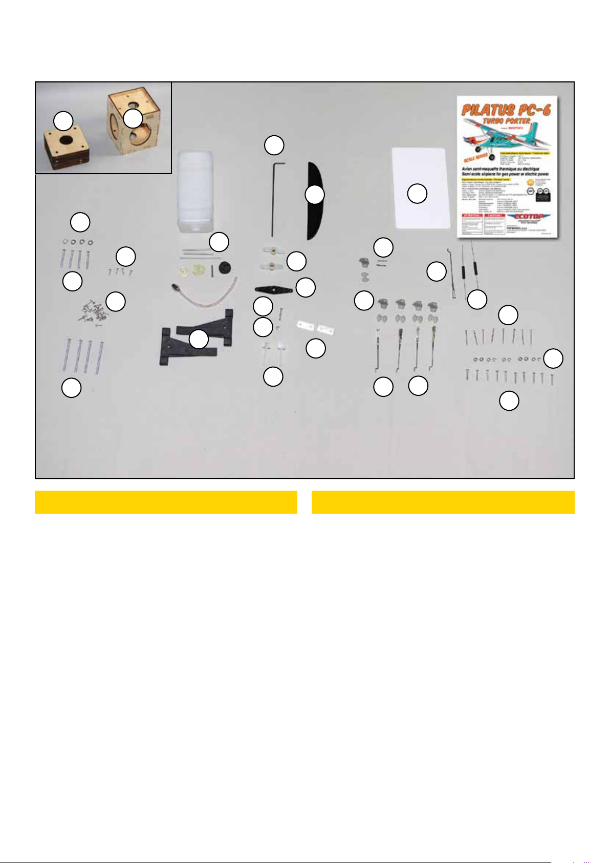
CONTENU DU KIT KIT CONTENT
PIECES FUSELAGE
(F1) Fuselage avec trappes amovibles et roulette AR ........1
(F2) Capot moteur en fibre de verre..........................................1
(F3) Fausse tuyère........................................................................... 2
(F4) Pare-brise ...................................................................................1
(F5) Commande de direction.........................................................1
(F6) Commande de gaz ....................................................................1
(F7) Entretoise pour moteur thermique ..................................1
(F8) Bâti pour moteur électrique ...............................................1
(F9) Réservoir ...................................................................................1
(F10) Bâti pour moteur thermique ............................1 G & 1 D
(F11) Casquette de tableau de bord............................................1
(F12) Trappe de fuselage................................................................1
(F13) Commande de profondeur avec chape et écrou .........1
PIÈCES AILES
(A1) Aile gauche avec aileron et volet .....................................1
(A2) Aile droite avec aileron et volet.......................................1
(A3) Mât d'aile................................................ 1 gauche et 1 droit
(A4) Clé d'aile aluminium .............................................................1
(A5) Commande d'aileron avec chape et écrou .................... 2
(A6) Commande de volet avec chape et écrou ...................... 2
(A7) Vis nylon de fixation d'aile ............................................... 2
PIECES EMPENNAGES
(E1) Stab horizontal avec gouverne de profondeur.............1
(E2) Dérive avec gouverne de direction ..................................1
FUSE PARTS
(F1) Fuselage with removable hatches and tail gear.........1
(F2) Glass fiber cowl........................................................................1
(F3) Dummy exhaust...................................................................... 2
(F4) Wind shield ................................................................................1
(F5) Rudder pushrod .......................................................................1
(F6) Throttle pushrod......................................................................1
(F7) Spacer for gas engine.............................................................1
(F8) Electro motor mount ..............................................................1
(F9) Fuel tank ....................................................................................1
(F10) Gas engine mount .................................................. 1 L & 1 R
(F11) Top of instrument panel......................................................1
(F12) Fuselage hatch .......................................................................1
(F13) Elevator pushrod with clevis and nut ..........................1
WINGS PARTS
(A1) Left wing with aileron and flap........................................1
(A2) Right wing with aileron and flap.....................................1
(A3) Wing strut .......................................................... 1 left 1 right
(A4) Aluminium wing joiner ........................................................1
(A5) Aileron pushrod with clevis and nut............................. 2
(A6) Flap pushrod with clevis and nut ................................... 2
(A7) Nylon wing bolt....................................................................... 2
PIECES EMPENNAGES
(E1) Horizontal stabilizer with elevator .................................1
(E2) Verical stabilizer with rudder ..........................................1
F1
F2
A2
A3
A1
A4
F6
F4
E2
F3
E1
T1
T4
F5
PILATUS PC-6 TURBO PORTER ARF
Notice Ecotop - Page 7 - Pilatus PC-6 Turbo Porter 2.07m ARF
CONTENU DU KIT KIT CONTENT
(E3) Manivelle de commande de roulette AR.........................1
(E4) Bras de commande ................................................................. 2
(E5) Rallonge de bras de commande..........................................1
(E6) Tourillon bois dur Ø 6 x 30 mm (Monté sur stab) ........... 2
TRAIN D'ATTERRISSAGE
(T1) Train principal préassemblé avec roue ........... 1 G & 1D
(T2) Ressort de commande de roulette AR............................. 2
(T3) Cavalier de fixation de train principal......................... 2
(T4) Ensemble roulette de queue préassemblé ......................1
PIECES DIVERSES
(D1) Guignol nylon et contreplaque.......................................... 5
(D2) Bande velcro L 300 mm (Non illustré) .......................... 2
Notice de montage .............................................................................1
VISSERIE
(V1) Vis M2 x 25............................................................................... 8
(V2) Vis M2 x 15............................................................................... 2
(V3) Vis M3 x 16 mm..................................................................... 10
(V4) Vis M3 x 20 mm.......................................................................1
(V5) Vis M4 x 25 mm...................................................................... 4
(V6) Vis M4 x 60 mm...................................................................... 4
(V7) Vis auto-taraudante Ø 2,2 x 9,5 mm.............................30
(V8) Vis auto-taraudante Ø 2,2 x 12 mm................................ 4
(V9) Rondelle plate Ø 3 mm .........................................................11
(V10) Rondelle plate Ø 4 mm........................................................ 4
(E3) Tail gear control wire............................................................1
(E4) Control arm............................................................................... 2
(E5) Control arm extension...........................................................1
(E6) Hard wood dowel Ø6 x 30 mm (fitted in stab)............ 2
LANDING GEAR
(T1)
Pre-assembled main landing gear with wheel
.. 1 L & 1 R
(T2) Spring for tail gear control................................................ 2
(T3) Strap for main landing gear .............................................. 2
(T4) Tail gear assembly..................................................................1
MISC PARTS
(D1) Nylon control horn with counterplate........................... 5
(D2) Hook and loop material L 300 mm (Not shown) ........ 2
Assembly manual ..............................................................................1
HARDWARE
(V1) M2 x 25 Machine screw ....................................................... 8
(V2) M2 x 15 Machine screw ....................................................... 2
(V3) M3 x 16 mm Machine screw............................................. 10
(V4) M3 x 20 mm Machine screw ...............................................1
(V5) M4 x 25 mm Machine screw.............................................. 4
(V6) M4 x 60 mm Machine screw.............................................. 4
(V7) Ø2,2 x 9,5 mm self tapping crew...................................30
(V8) Ø 2,2 x 12 mm self tapping crew ...................................... 4
(V9) ID 3 mm flat washer.............................................................11
(V10) ID 4 mm flat washer........................................................... 4
PILATUS PC-6 TURBO PORTER ARF
F7 F8
F9
F10
F11
F13
F12
D1
A5 A6
A7
T3
T2
E3
E4
E5
V3
V2
V1
V6
V7
V8
V9
V9
V5
V10
V4
Notice Ecotop - Page 8 - Pilatus PC-6 Turbo Porter 2.07m ARF
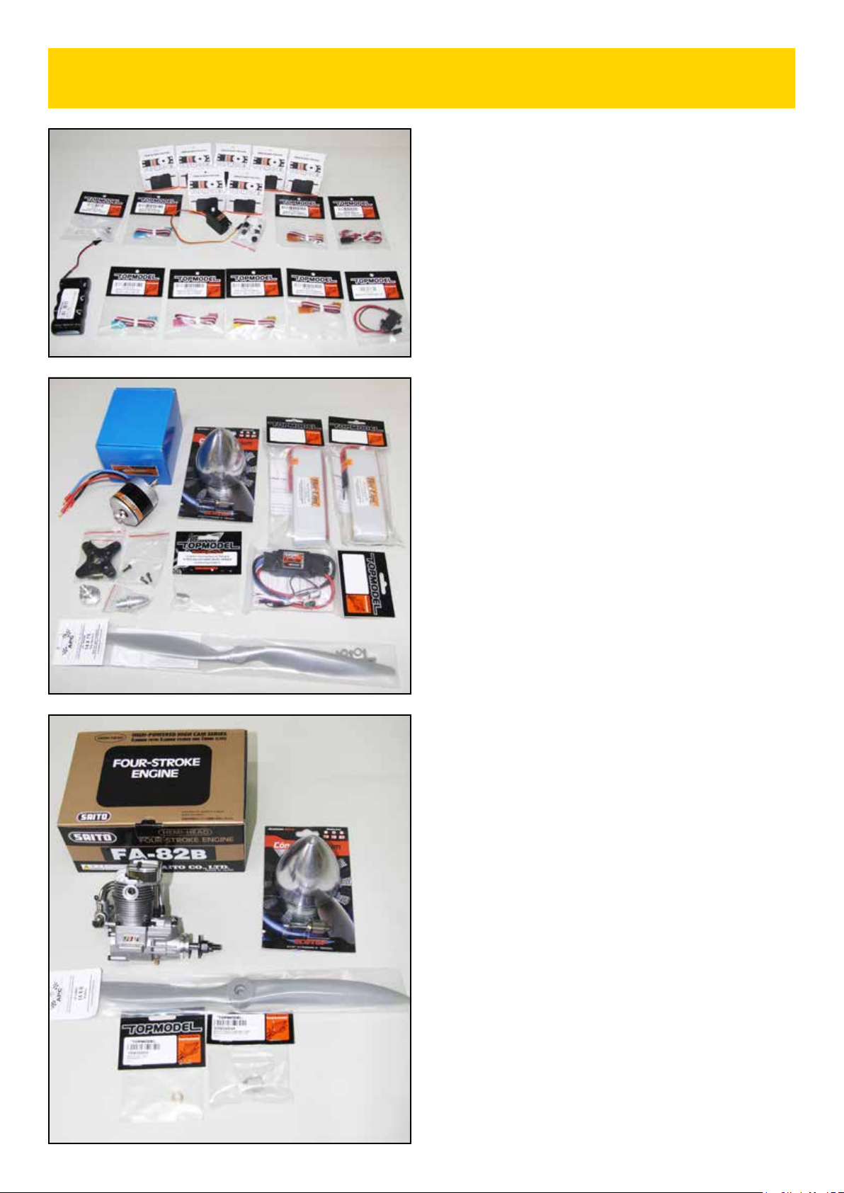
A RAJOUTER POUR ASSEMBLER CE KIT
TO BE ADDED TO BUILD THIS KIT
●Ensemble radio
- 1 émetteur avec au minimum 7 voies.
- 1 récepteur (Recommandé : Jeti Duplex R8 EX # 007R8)
- 6 servos TOPMODEL S3217 (#200S3217)
(NOTE : 7 servos S3217 en version thermique)
- 2 Rallonges de servos de 10 cm
- 4 Rallonges de servos de 30 cm
- 3 Rallonges de servos de 50 cm (4 en version électrique)
- 1 terminal de connexion seul (# 0434071)
- 1 cordon interrupteur
- 1 accu de réception 4,8 V 3600 mAh.
●Motorisation électrique
- 1 moteur XPower XC5025/16 (# 099C502516)
- 1 contrôleur brushless XPower XREG60 (# 099REG60)
- 2 Packs LiPo HOTLIPS 11,1V 4000 mAh 3S1P PK
(#09140003S1P40)
- 1 hélice APC-E 14 x 7"
- 1 cône aluminium Ø76 mm (# 066AS76)
- 1 adaptateur M8/M5 (# 066ASA0044)
●Motorisation thermique
- 1 moteur OS 65 AX 2 temps
- 1 hélice 13 x 6
- 1 cône aluminium Ø76 mm (# 066AS76)
ou
- 1 moteur Saito FA-82B 4 temps
- 1 hélice APC 14 x 6"
- 1 cône aluminium Ø76 mm (# 066AS76)
- 1 adaptateur M7/M4 (# 066ASA0038)
- 1 insert Øint. 7 mm (# 066ASB0066)
- 1 vis CHC M4 x 45 mm
●Radio set
- 1 Tx with at least 7 channels.
- 1 receiver (Suggested : Jeti Duplex R8 EX # 007R8)
- 6 servos TOPMODEL S3217(# 200S3217)
(NOTE : 7 servos S3217 for gas power version)
- 2 x 10 cm servo extensions
- 4 x 30 cm servo extensions
- 3 x 50 cm servo extensions (4 for electro)
- 1 Servo extension mount only (# 0434071)
- 1 Switch harness
- 1 x 4,8 V 3600 mAh NiMh Rx battery
●Electric power (EP)
- 1 XPower motor XC5025/16 (# 099C502516)
- 1 XPower XREG60 ESC (# 099REG60)
- 2 LiPo Battery HOTLIPS 11,1V 4000mAh 3S1P PK
(#09140003S1P40)
- 1 propeller APC-E 14 x 7"
- 1 aluminium spinner Ø76 mm (# 066AS76)
- 1 spinner adapter nut M8x1.25/M5 (# 066ASA0044)
●Gas power (GP)
- 1 OS 65 AX 2-stroke engine
- 1 APC 13 x 6 propeller
- 1 aluminium spinner Ø76 mm (# 066AS76)
or
- 1 Saïto FA-82B 4-stroke engine
- 1 APC 14 x 6" propeller
- 1 aluminium spinner Ø76 mm (# 066AS76)
- 1 spinner adapter nut M7/M4 (# 066ASA0038)
- 1 bushing Øint. 7 mm (# 066ASB0066)
- 1 M4 x 45 mm Socket head screw
Notice Ecotop - Page 9 - Pilatus PC-6 Turbo Porter 2.07m ARF
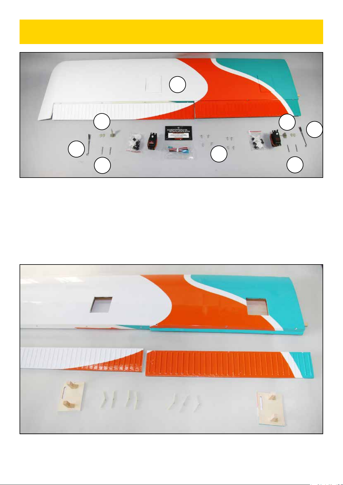
PIECES AILES
(A2) Aile droite..................................................................................1
(A5) Commande d'aileron avec chape.......................................1
(A6) Commande de volet avec chape.........................................1
(D1) Guignol nylon avec contreplaque .................................... 2
(V1) Vis M2 x 25 mm ...................................................................... 4
(V7) Vis auto-taraudante 2,2 x 9,5 mm .................................. 8
ACCESSOIRES (non fournis)
Servo standard .................................................................................. 2
Rallonge de servo de 10 cm (Volet - non photographiée) ..1
Rallonge de servo de 50 cm (Aileron) .......................................1
WING PARTS
(A2) Right wing .................................................................................1
(A5) Aileron pushrod with clevis...............................................1
(A6) Flap pushrod with clevis .....................................................1
(D1) Nylon control horn with counterplate........................... 2
(V1) M2 x 25 mm machine screw .............................................. 4
(V7) 2,2 x 9,5 mm self tapping screw ...................................... 8
ACCESSORIES (not included)
Standard servo .................................................................................. 2
10 cm servo extension (Flap - not shown) ...............................1
50 cm servo extension (Aileron).................................................1
MONTAGE DE L'AILE DROITE
RIGHT WING ASSEMBLY
A2
A5
A6
D1
V1 V1
V7
D1
1) Enlevez les adhésifs qui maintiennent les trappes de servos.
Remove adhesive tapes which retain servo hatches.
2) Démontez l'aileron et le volet et mettez les charnières de
côté.
Remove aileron and flap from the wing and set hinges aside.
Notice Ecotop - Page 10 - Pilatus PC-6 Turbo Porter 2.07m ARF
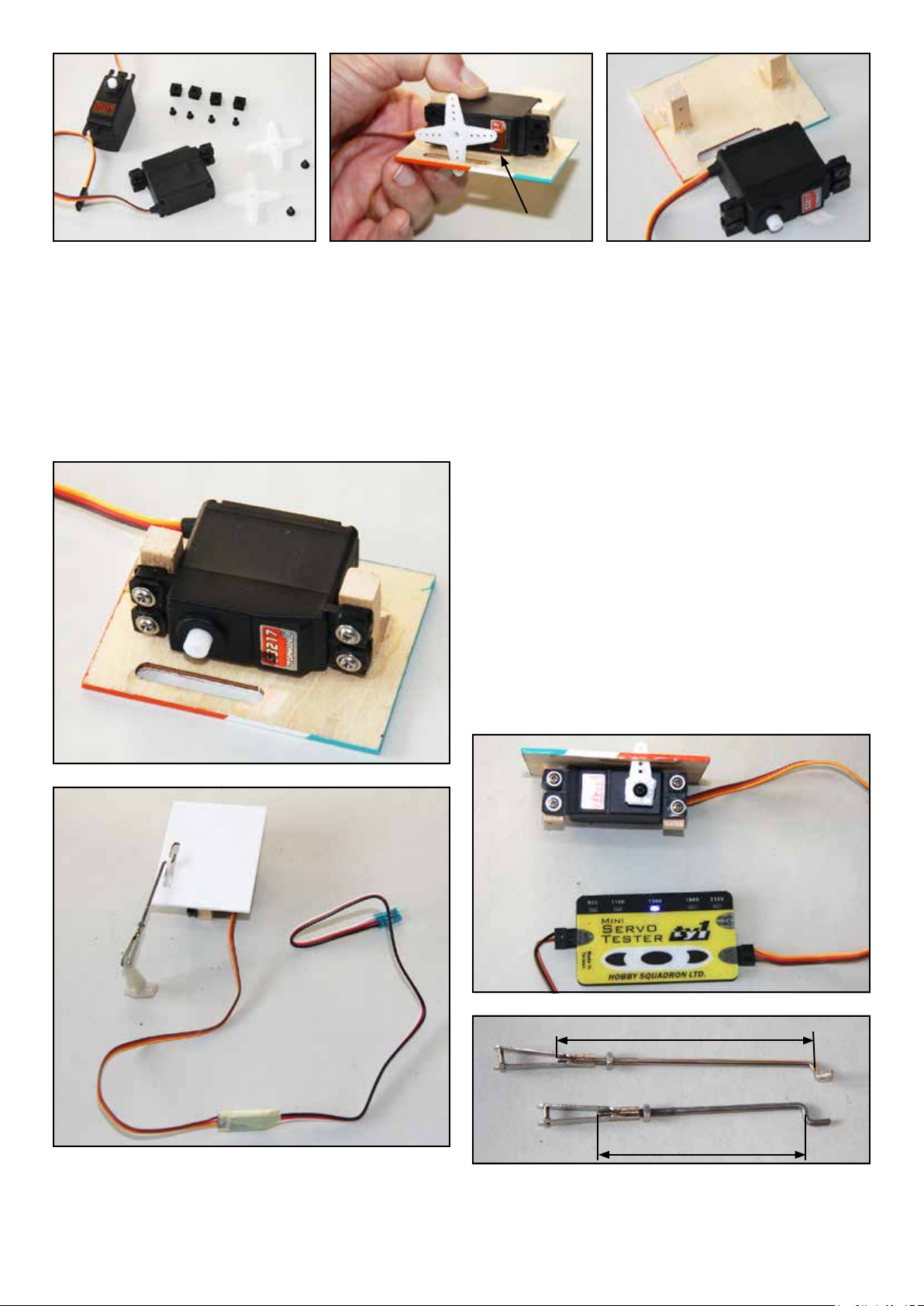
3) Montez les silentblocs et les rivets sur les servos. Note: la
base des rivets doit être sous les pattes du servo.
Install grommets and eyelets on the servos. Note : The base
of the eyelets should be under the mounting brackets of the
servo.
4) Placez le servo sur la trappe correspondante avec une cale de
0,5 mm et percez un trou de 1,6 mm dans les blocs de bois dur
au travers de chaque rivet.
Fit each servo on his hatch, with a 0,5 mm spacer, and drill
a 1,6 mm hole in the hard wood blocks through each eyelet.
5) Déposez le servo. Vissez une vis de servo dans chaque trou et
démontez-la. Mettez une goutte de cyano fluide dans chaque
trou pour durcir le bois. Laissez sécher la cyano.
Unmount the servo. Insert a servo screw in each hole, and
remove the screw. Add a drop of thin CA in each hole to
harden the wood. Let the CA cures fully.
6) Vissez les servos sur les trappes avec 4 vis de servos (sans
cale). La tête du servo doit être centrée sur la fente de la trappe.
Secure the servos (without spacer) on the hatches using 4
servo screw. The servo head should be centered over the slot
of the hatch.
7) Avec votre ensemble radio ou un testeur de servo, mettez
le servo au neutre. Coupez les bras inutiles d'un palonnier
et montez ce palonnier perpendiculaire au boîtier du servo.
N'oubliez pas la vis de palonnier.
Using your radio system or a servo tester, center the servo.
Cut unused arms of a servo arm, and fit this servo arm
perpendicular to the servo housing.
9) Préparez les commandes d'aileron et de volet. La commande
de volet est la plus longue.
Locate the aileron and flap pushrod. Flap pushrod is longer.
8) Branchez une rallonge de 50 cm sur le servo d'aileron.
Branchez une rallonge de 10 cm sur le servo de volet.
Connect a 50 cm extension on the aileron servo and a 10 cm
extension on the flap servo.
Volet / Flap : 60 mm
Aileron : 50 mm
Cale/spacer
Notice Ecotop - Page 11 - Pilatus PC-6 Turbo Porter 2.07m ARF
12) Glissez le fil du servo d'aileron au travers des nervures et
sortez-le à l'emplanture. Mettez la trappe de servo d'aileron en
place (Note: sur les kits de série, la trappe est encastrée dans le
profil de l'aile).
Route the aileron servo wire through the ribs and exit at the
wing root. Fit the aileron servo hatch in position (Note : on
production kits, the hatch is embedded into the wing).
13) Percez un trou de 1,6 mm dans chaque angle de la trappe
et dans l'aile. Déposez la trappe. Vissez une vis de servo dans
chaque trou de l'aile et démontez-la. Mettez une goutte de
cyano fluide dans chaque trou pour durcir le bois. Laissez sécher
la cyano. Fixez la trappe avec 4 vis à bois de 2,2 x 9,5 mm.
Drill a 1,6 mm hole in each corner of the hatch and in the
wing.
Remove the hatch. Insert a servo screw in each hole of
the wing, and remove the screw. Add a drop of thin CA in each
hole to harden the wood. Let the CA cures fully. Secure the
hatch using 4 2,2 x 9,5 mm self tapping screws.
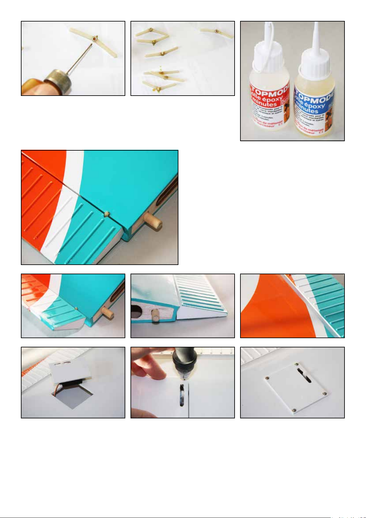
10) Déposez une goutte d'huile sur l'axe de chaque charnière d'aileron et de volet.
Veillez à ne pas mettre d'huile sur le corps des charnières. Ensuite, préparez un peu
d'époxy 30 minutes.
Add a drop of oil on the axle of aileron and flap hinges. Be sure to not put oil on the
body of hinges.Then, mix some 30 minutes epoxy.
11) Collez les charnières dans l'aile, dans l'aileron et dans le
volet à l'époxy en évitant de mettre de la colle sur les axes.
La position des charnières de volet doit permettre d'avoir
l'extrados du volet aligné avec l'extrados de l'aile. Vérifiez le
débattement du volet et de l'aileron. Vous pouvez contrôler
le collage du tourillon à l'emplanture et si nécessaire le coller
également à l'époxy.
Glue the hinges into the wing and into aileron and flap. Take
care to not put epoxy on the axles. The flap hinges should be
fitted so that the upper side of the flap is in line with the upper
side of the wing. Check the correct movement of the flap and
of the aileron. You can check also if the wing dowel are well
attached and add epoxy glue if needed.
Notice Ecotop - Page 12 - Pilatus PC-6 Turbo Porter 2.07m ARF
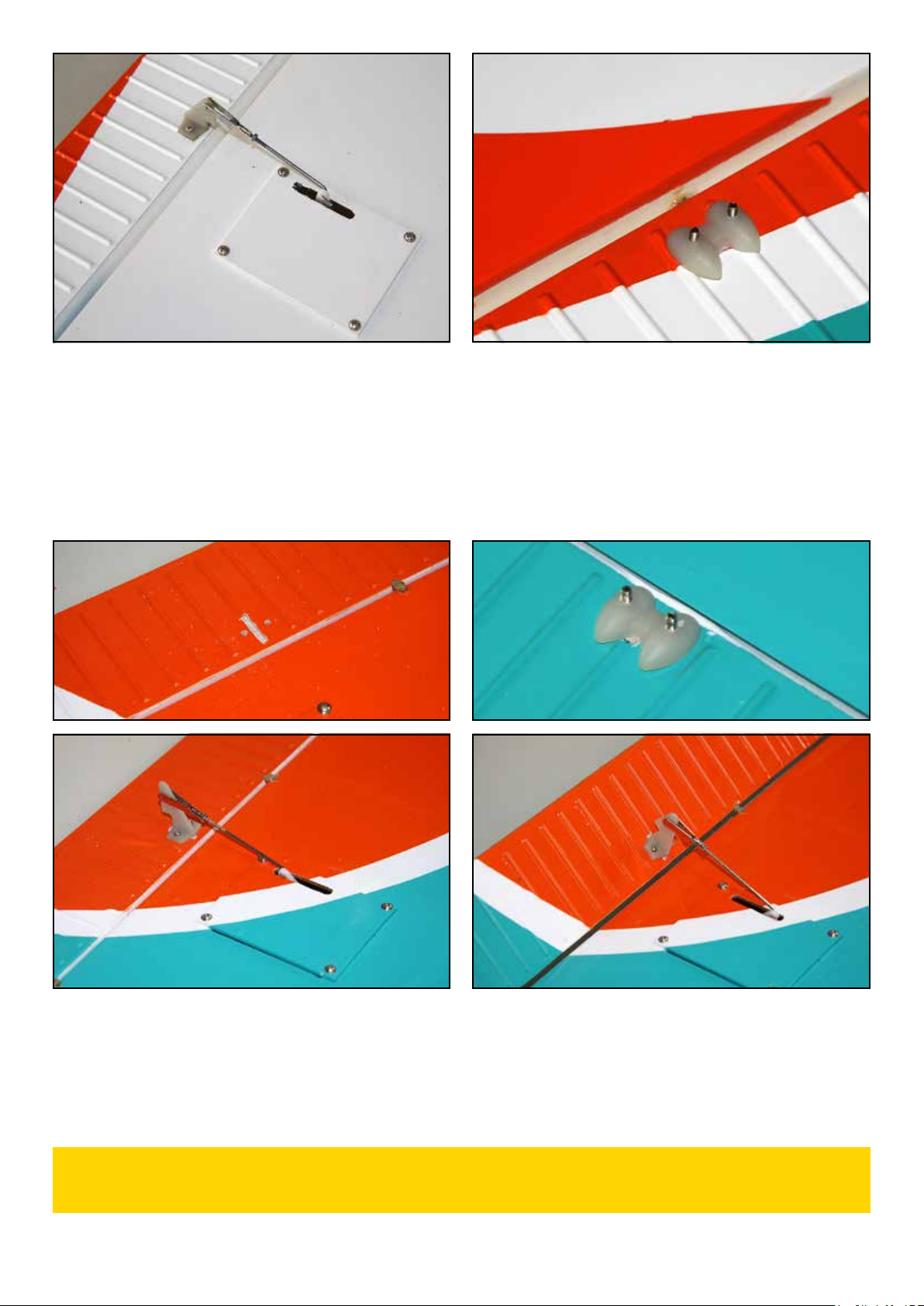
14) Tracez la position du guignol d'aileron, aligné avec le
palonnier de servo. Coupez avec un cutter les portions de
nervurages pouvant gêner la mise en place du guignol, pour
que celui-ci repose à plat sous l'aileron. Vissez le guignol dans
l'aileron avec deux vis M2 x 25 mm et les contreplaques à
l'extrados.
Mark the location of the control horn on the aileron, in line
with the servo arm. Using a hobby knife, cut the ribbings if they
interfere with the control horn base, so that the control horn
stand flat under the aileron. Secure the control horn using two
M2 x 25 mm machine screws and the nylon counterplates.
15) Montez la commande d'aileron et réglez le neutre de la
gouverne avec la chape. Bloquez le contre-écrou.
Install the aileron linkage and set the neutral using the clevis.
Tighten the nut against the clevis.
Repétez les opérations 1 à 16 de l'aile droite pour l'aile gauche.
Repeat steps 1 to 16 of right wing to assemble left wing.
16) Procédez de la même façon pour monter le servo et la commande de volet. Notez que le guignol doit être monté "tourné
vers l'arrière", afin d'avoir une cinématique correcte de la commande sur toute la plage de débattement. Notez que les positions
extrêmes du servo doivent permettre de placer les volets en position rentrée et complètement sortis.
Do the same to fit the flap servo and its linkage. Note that the control horn is fitted inverted, so the movement of the flap will
be correct on the full throw range. The end travel of the servo should allow to obtain the neutral position of the flap and the
maximum deflexion.
MONTAGE DE L'AILE GAUCHE
LEFT WING ASSEMBLY
Notice Ecotop - Page 13 - Pilatus PC-6 Turbo Porter 2.07m ARF
MONTAGE DE LA CLE D'AILE
WING JOINER ASSEMBLY
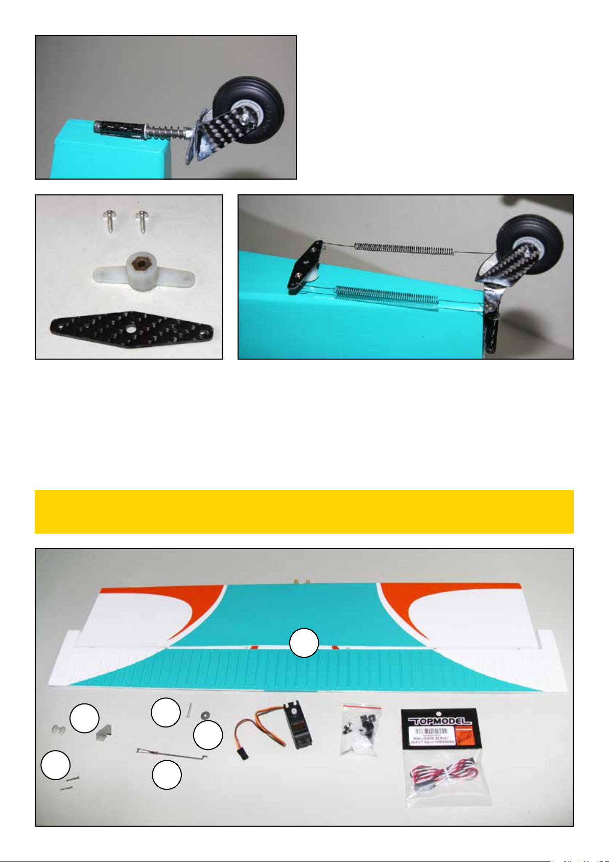
MONTAGE DE LA DERIVE ET DE LA ROULETTE
VERTICAL STABILIZER AND TAIL GEAR ASSEMBLY
PIECES A UTILISER
(F1) Fuselage.......................................................................................1
(A4) Clé d'aile aluminium .............................................................1
(V3) Vis M3 x 16 mm....................................................................... 2
(V9) Rondelle plate Ø 3 mm .......................................................... 2
PARTS TO BE USED
(F1) Fuselage.......................................................................................1
(A4) Aluminium wing joiner ........................................................1
(V3) M3 x 16 mm machine screw............................................... 2
(V9) ID 3 mm flat washer ............................................................. 2
PIECES A UTILISER
(F1) Fuselage.................................................................... 1
(E2) Dérive avec gouverne de direction ............... 1
(F5) Commande de direction...................................... 1
(E3) Manivelle de commande de roulette AR...... 1
(E4) Bras de commande ...............................................2
(E5) Rallonge de bras de commande....................... 1
(V7) Vis auto-taraudante Ø 2,2 x 9,5 mm.............2
(T4) Ensemble roulette de queue ............................. 1
Servo standard (non illustré) ................................... 1
PARTS TO BE USED
(F1) Fuselage.................................................................... 1
(E2) Vertical stabilizer with rudder...................... 1
(F5) Rudder pushrod .................................................... 1
(E3) Tail gear steering wire....................................... 1
(E4) Steering arm...........................................................2
(E5) Steering arm extension...................................... 1
(V7) Ø 2,2 x 9,5 mm self tapping crew ...................2
(T4) Tail gear assembly............................................... 1
Standard servo (not shown)....................................... 1
F1
A4
V3
V9
1) Glissez la clé d'aile en aluminium dans le fuselage, en
respectant le sens du dièdre.
Slide the aluminium wing joiner into the fuse. Check out the
direction of dihedral.
2) Fixez la clé à l'aide de deux vis M3 x 16 mm et de deux
rondelles de 3 mm. Des écrous à griffes sont en place dans le
fuselage.
Using two M3 x 16 mm machine screws and two ID 3 mm flat
washers, secure the wing joiner. Blind nuts are already fitted in
the fuselage.
F1
T4
F5
E3
E2
E5
E4
V7

Notice Ecotop - Page 14 - Pilatus PC-6 Turbo Porter 2.07m ARF
1) Démontez la gouverne de direction et mettez les charnières
de côté. Découper l'entoilage pour dégager les surfaces de
collage de la dérive au pied de dérive et sous l'arête.
Remove the rudder and set hinges aside. With a sharp hobby
knife, cut and remove the covering from the bonding surfaces,
at the base of the fin and under the apex.
2) Montez à blanc la dérive sur le fuselage, centrez l'arête sur le
fuselage et maintenez-la en place avec une épingle.
Test fit the fin on the fuse, center the apex and attach it
temporarily with a pin.
3) Tracez le contour de la base de la dérive sur le fuselage avec
un feutre fin.
Mark the outline of the base of the fin on the fuse with a felt
pen.
4) Découpez l'entoilage du dessus du fuselage 0,5 mm à
l'intérieur du tracé. Nettoyez le tracé à l'alcool. Ne pas entailler
le bois!!!
Cut the covering on the top of fuse 0,5 mm inside the outline.
Clean the marking using alcohol. Do not cut the wood!!!
5) Déposez une goutte d'huile sur l'axe de chaque charnière de direction. Veillez à ne pas mettre d'huile sur le corps des charnières.
Ensuite, préparez un peu d'époxy 30 minutes.
Add a drop of oil on the axle of rudder hinges. Be sure to not put oil ont the body of hinges.Then, mix some 30 minutes epoxy.
6) Collez les charnières dans la gouverne de direction avec de l'époxy. Collez également la manivelle de commande de roulette
de queue à l'époxy à la base de la gouverne de direction.
Secure the hinges inside the rudder using epoxy. Secure also the tail gear steering wire inside the base of the rudder using epoxy.
7) Collez les charnières dans la dérive à l'époxy. La manivelle
de commande de roulette de queue ne doit pas être collée
contre la dérive. Laissez sêcher complètement l'époxy.
Secure the hinges inside the rudder using epoxy. The tail gear
steering wire should not be glued against the fin. Wait until
epoxy is fully dried.

Notice Ecotop - Page 15 - Pilatus PC-6 Turbo Porter 2.07m ARF
9) Glissez la commande de direction avec le bras de commande dans le fuselage. En mettant la dérive en place, glissez le bras de
commande autour de la manivelle de commande de roulette de queue (flèche rouge). Collez la dérive sur le fuselage et dans le
couple arrière à l'époxy. La manivelle passe au travers du fond de fuselage renforcé par une plaque de contreplaqué (flèche verte).
Insert the rudder pushrod equiped with the steering arm inside the fuselage. When you install the fin, slide the steering arm
around the tail wheel steering wire (red arrow). Secure the fin on the fuselage and inside the rear former with epoxy glue. The
tail wheel steering wire exit under the fuselage, through the reinforcement made with plywood (green arrow).
8) Montez un des bras de commande sur le pli en Z de la commande de direction. Vous
pouvez couper le bras inutile en cas de besoin. (Il est possible qu'un des bras de commande
du kit n'ait déjà qu'une branche.)
Fit one steering arm on the Z bend of the rudder pushrod. If needed, you can cut the unused
side of the arm. (You may find a steering arm with only one arm in the kit)
10) Une fois l'époxy sèche, bloquez le bras de commande contre la manivelle de
commande de roulette de queue en serrant la vis de pression avec un tournevis
hexagonal. Le bras doit être perpendiculaire à la gouverne de direction, et
positionné en hauteur pour qu'il passe dans l'encoche du couple.
When epoxy has cured, attach the steering arm on the tail gear steering wire, by
tightening the set screw of the steering arm with a hexagonal screwdriver. The
steering arm should be perpendicular to the rudder, and positionned so that it
passes freely through the notch made on the plywood former.
11) Equipez le servo
de direction avec
ses silent-blocs
et vissez-le sur la
platine dans le fuselage. Réglez et branchez la commande de direction sur le
palonnier de servo.
Install the grommets on the rudder servo, and secure the servo on its tray inside
the fuselage. Set the clevis and connect the pushrod to the servo arm.
Notice Ecotop - Page 16 - Pilatus PC-6 Turbo Porter 2.07m ARF
13) Utilisez le second bras de commande comme gabarit pour tracer la position de deux trous de 2 mm sur la rallonge de bras de
commande. Percez ces deux trous, puis vissez la rallonge sur le bras de commande avec deux auto-taraudante de 2,2 x 9,5 mm.
Fixez le bras de commande sous le fuselage en le glissant sur la manivelle de commande de la roulette de queue, et en serrant la
vis de pression. Enfin, montez les deux ressorts de commande de la roulette de queue en pliant leurs extrémités avec une petite
pince.
Using the second steering arm as a template, mark the location of two Ø2 mm holes on the steering arm extension. Drill these
two holes, and secure the extension on the steering arm using two 2,2 x 9,5 mm self tapping screws. Install the steering arm
under the fuselage, on the tail gear steering wire, and tighten the set screw inside the steering arm. Install the two springs between
the steering arm extension and the arms of the tail gear. Use small pliers to bend the end of the springs.
MONTAGE DU STABILISATEUR HORIZONTAL
HORIZONTAL STABILIZER ASSEMBLY
12) Découpez l'entoilage pour dégager la fente à l'arrière du
fuselage et collez l'ensemble roulette de queue à l'époxy.
Laissez sécher complètement.
Cut the covering film to clear up the notch at the rear of
fuselage and glue the tail gear assembly using 30 minutes
epoxy gmue. Wait for complete cure.
E1
D1
V2
V4
V9
F13

Notice Ecotop - Page 17 - Pilatus PC-6 Turbo Porter 2.07m ARF
PIECES A UTILISER
(E1) Stab horizontal avec gouverne de profondeur.............1
(V4) Vis M3 x 20 mm.......................................................................1
(V9) Rondelle plate Ø 3 mm ...........................................................1
(F13) Commande de profondeur avec chape...........................1
(D1) Guignol nylon et contreplaque...........................................1
(V2) Vis M2 x 15............................................................................... 2
Servo standard ...................................................................................1
Rallonge de servo de 50 cm ...........................................................1
PIECES A UTILISER
(E1) Horizontal stabilizer with elevator .................................1
(V4) M3 x 20 mm Machine screw ...............................................1
(V9) ID 3 mm flat washer ..............................................................1
(F13) Elevator pushrod with clevis ...........................................1
(D1) Nylon control horn with counterplate............................1
(V2) M2 x 15 Machine screw ....................................................... 2
Standard servo ...................................................................................1
50 cm servo extension .....................................................................1
10 - 15 mm
1) Vérifiez le collage des tourillons du stab. Si nécessaire,
collez-les à l'époxy. Ils doivent dépasser du bord d'attaque de
10 à 15 mm.
Check if dowels are correctly glued. If neccessary, apply epoxy.
They should protrude 10-15 mm from the leading edge.
2) Coupez l'entoilage pour dégager la fente de passage de la
manivelle de commande de la roulette de queue.
Cut the covering film to clear up the notch for the tail gear
steering wire.
3) Branchez la rallonge de 50 cm sur le fil du servo et
verrouillez le connecteur avec de l'adhésif ou de la gaine
thermorétractable (non fournie). Découpez l'entoilage au
niveau du logement du servo de profondeur. Passez le fil du
servo dans le fuselage.
Connect the 50 cm servo extension to the servo wire, and
secure the connexion using adhesive tape or shrink tube (not
included). Cut the covering film at the elevator servo location.
Install the servo wire inside the fuselage.
4) Equipez le servo de ses silentblocs et vissez-le en place.
Montez la commande sur le palonnier.
Fit the gromets on the servo, and attach the servo in position.
Install the elevator pushrod on the servo arm.
5) Tracez la position du guignol de profondeur sous la
gouverne, aligné avec le palonnier du servo. Vissez le guignol
avec deux vis M2 X 15 mm et la contreplaque en nylon.
Mark the location for the control horn under the elevator, in
line with the servo arm. Secure the control horn using two M2
x 15 mm machine screw and the nylon counterplate.
6) Comme pour les ailerons et les volets, collez les charnières
à l'époxy dans le stabilisateur et la gouverne de profondeur.
N'oubliez pas d’huiler les axes pour ne pas les coller.
As you did for ailerons and flaps, use epoxy to glue the hinges
into the stab and into the elevator. Don't forget to add a drop
of oil on each axle to avoid glueing.
7) Mettez le stab en place sur le fuselage et fixez-le avec une vis
M3 x 20 mm et une rondelle Ø3 mm.
Install the stab on the fuse, and secure it using a M3 x 20 mm
machine screw and an ID 3 mm flat washer.
8) Réglez la chape et branchez-la sur le guignol de profondeur.
Set the clevis and connect it on the elevator control horn.

Notice Ecotop - Page 18 - Pilatus PC-6 Turbo Porter 2.07m ARF
MONTAGE DU TRAIN PRINCIPAL
MAIN GEAR ASSEMBLY
PIECES A UTILISER
(T1) Train principal pré-assemblé avec roue.......... 1 G & 1D
(T3) Cavalier de fixation de train principal......................... 2
(V3) Vis M3 x 16 mm (Non illustrées)..................................... 4
(V9) Rondelle plate Ø 3 mm (Non illustrées)......................... 4
PARTS TO BE USED
(T1) Pre-assembled main landing gear w/wheel .. 1 L & 1 R
(T3) Strap for main landing gear .............................................. 2
(V3) M3 x 16 mm Machine screw (Not shown) .................... 4
(V9) ID 3 mm flat washer (Not shown)................................... 4
1) Vissez en premier la ferrure de fixation en haut de
l'amortisseur dans l'insert du flanc de fuselage.
First, attach the fitting at the top of the shock absorber inside
the blind nut located in the fuse side with the screw.
2) Placez les jambes des trains principaux dans l'encoche sous
le fuselage, et fixez-les avec les deux cavaliers en aluminium,
quatre vis M3 x 16 mm et quatre rondelles de 4 mm.
Insert the main gear legs into the notch at the bottom of the
fuselage and secure them using the two aluminium straps,
four M3 x 16 mm metal screws and four ID 4 mm flat washers.
3) Contrôlez le serrage des bagues d'arrêt de roues et mettez
du frein filet sur les vis de pression.
Check the wheels collars and add threadlock compound on
the set screws.
T3

Notice Ecotop - Page 19 - Pilatus PC-6 Turbo Porter 2.07m ARF
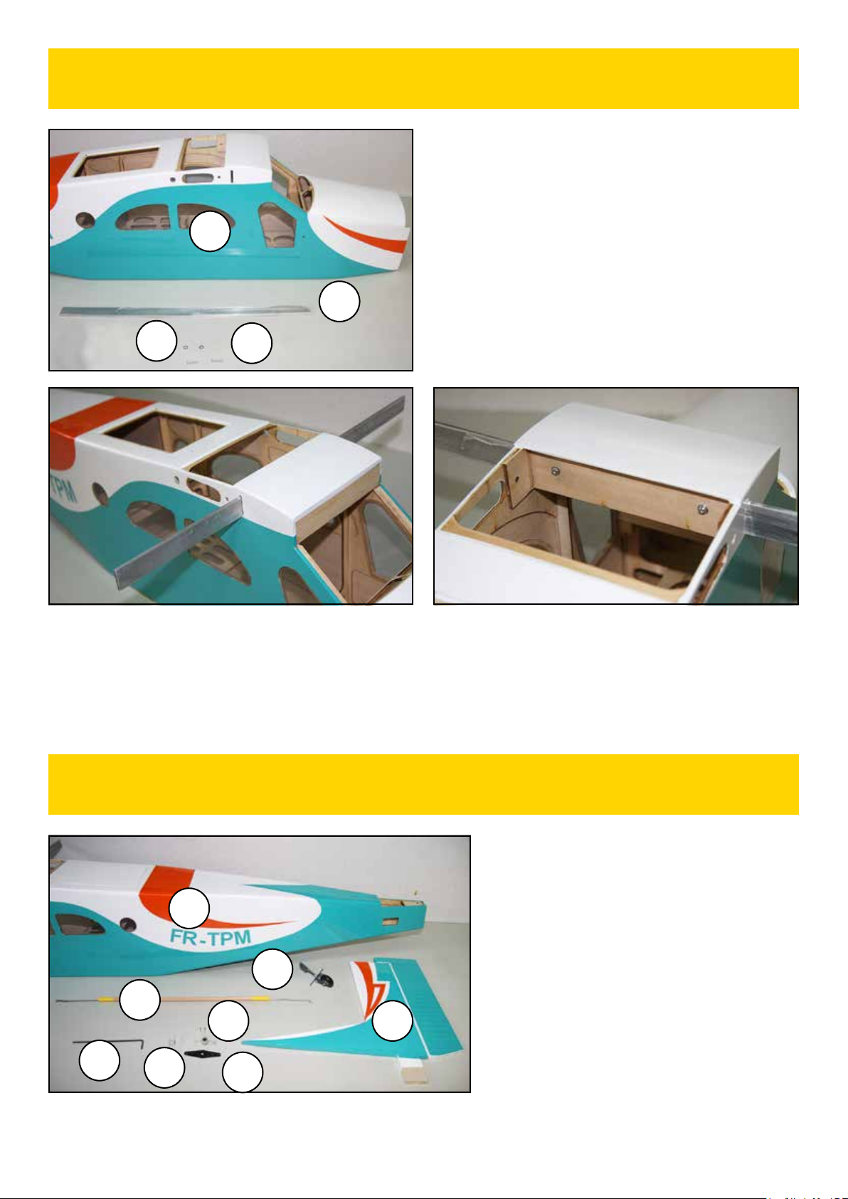
Vous pouvez faire un montage à blanc de votre Turbo Porter.
You can test fit your Turbo Porter.
VERSION MOTEUR THERMIQUE
GAS ENGINE VERSION
NOTE : Si vous avez choisi de monter un moteur électrique, passez directement en page 23.
NOTE : If you choose electric power, skip to page 23.
F7 V6
V10
F10
F9
PIECES A UTILISER
(F10) Bâti pour moteur thermique ............................1 G & 1 D
(F7) Entretoise pour moteur thermique ..................................1
(V6) Vis M4 x 60 mm...................................................................... 4
(V10) Rondelle plate Ø 4 mm........................................................ 4
(F9) Réservoir ...................................................................................1
(F2) Capot moteur en fibre de verre (Non représenté)......1
(F3) Fausse tuyère (Non représenté)....................................... 2
(V8) Vis auto)taraudante Ø 2,2 x 12 mm (Non représenté) ..4
(F6) Commande de gaz ....................................................................1
Moteur thermique 2 ou 4 temps (Non fourni).......................1
Vis CHC adaptée au moteur (non fournie) ............................. 4
Rondelle plate adaptée aux vis (non fournie)...................... 4
Ecrou nylstop adapté aux vis (non fourni) .......................... 4
Cône d'hélice diamètre 76 mm (Non fourni) ..........................1
Hélice (Non fournie) ........................................................................1
Servo standard (Non représenté, non fourni) .......................1
PARTS TO BE USED
(F10) Gas engine mount ......................................1 left & 1 right
(F7) Spacer for gas engine.............................................................1
(V6) M4 x 60 mm Machine screw.............................................. 4
(V10) ID 4 mm flat washer........................................................... 4
(F9) Réservoir ...................................................................................1
(F2) Glass fiber cowl (Not shown)..............................................1
(F3) Dummy exhaust (Not shown)............................................ 2
(V8) Ø 2,2 x 12 mm self tapping screw (Not shown) .......... 4
(F6) Throttle pushrod......................................................................1
Gas engine (2 or 4-stroke) (Not included) ..............................1
Socket head screw suitable for the engine (Not included)
. 4
Flat washer suitable for the SH screws (Not included).... 4
Lock nut suitable for the SH screws (Not included) .......... 4
3' spinner (Not included)................................................................1
Propeller (Not included).................................................................1
Standard servo (Not shown, not included) .............................1

Notice Ecotop - Page 20 - Pilatus PC-6 Turbo Porter 2.07m ARF
152 mm
1) Montez les deux demi-bâtis moteur sur l'entretoise CTP avec
4 vis M4 x 60 mm et 4 rondelles de 4 mm. Vissez l'ensemble
sur la cloison pare-feu en ne serrant pas complètement les vis
(des écrous prisonniers sont en place à l'arrière de la cloison
pare-feu).
Install the two motor half mount on the plywood spacer
using four M4 x 60 mm machine screws and four ID 4 mm
flat washers. Fit these elements on the firewall, but keep the
screws loose (blind nuts are factory installed at the backside
of the firewall).
2) Posez le moteur, cylindre vers le bas du fuselage, sur le
bâti, avec le plateau d'hélice à 152 mm de la cloison pare-feu.
Réglez l'écartement du bâti en fonction du moteur utilisé.
Tracez la position des trous de fixation sur les bras du bâti
moteur. Enlevez le moteur et serrez définitivement les vis
du bâti. Percez les trous de fixation du moteur avec un foret
adapté aux vis de fixation de votre moteur.
The engine will be mounted inverted, so be sure the mount
is attached to the firewall inverted. Place your engine on the
mount and adjust the lugs to match with the engine width
and then tighten the bolts. Install the engine on the mount,
cylinder facing to the bottom of fuse, so the distance from
the firewall to the front of the prop washer is 152mm. Mark the
location of engine holes on the mount. Remove the engine and
drill the holes with a drill bit matching with your motor screws.
3) Fixez le moteur sous le bâti avec quatre vis CHC de diamètre
adapté à votre moteur, quatre écrous nylstop et quatre
rondelles plates de diamètre adapté aux vis.
Secure the engine on the mount using four socket head screws,
four lock nuts and four flat washers suitable for your engine.
4) Tracez une marque (flèche rouge) sur la cloison pare-feu,
alignée sur le bras de commande du carburateur. Percez un
trou de 2,5 mm sur cette marque.
Draw a mark (red arrow) on the firewall, lined up with the arm
of the carburetor. Drill a 2,5 mm hole on this mark.
5) Passez la commande de gaz dans le trou et branchez la
chape sur le bras de commande du carburateur.
Slide in the throttle pushrod through the hole and connect the
clevis to the carburetor lever arm.
Other Ecotop Toy manuals

Ecotop
Ecotop BIDULE 55 User manual

Ecotop
Ecotop Spacewalker I 06604 User manual

Ecotop
Ecotop Schleicher Ka-8b User manual

Ecotop
Ecotop Schleicher Ka-8b User manual

Ecotop
Ecotop Schleicher Scale Series User manual

Ecotop
Ecotop 066GDHC2 User manual

Ecotop
Ecotop ARS 300 User manual

Ecotop
Ecotop PILATUS B4 User manual
Popular Toy manuals by other brands


Fisher-Price
Fisher-Price SPARKLING SYMPHONY CAROUSEL 73457 instruction sheet

Seagull Models
Seagull Models AT-6 TEXAN Assembly manual

Monogram
Monogram Twin Mustang F-82G manual

E-FLITE
E-FLITE Extra 260 3D Profile Assembly manual

Mattel
Mattel Max Steel instructions

PARKZONE
PARKZONE RTF P-51 MUSTANG BL instruction manual


