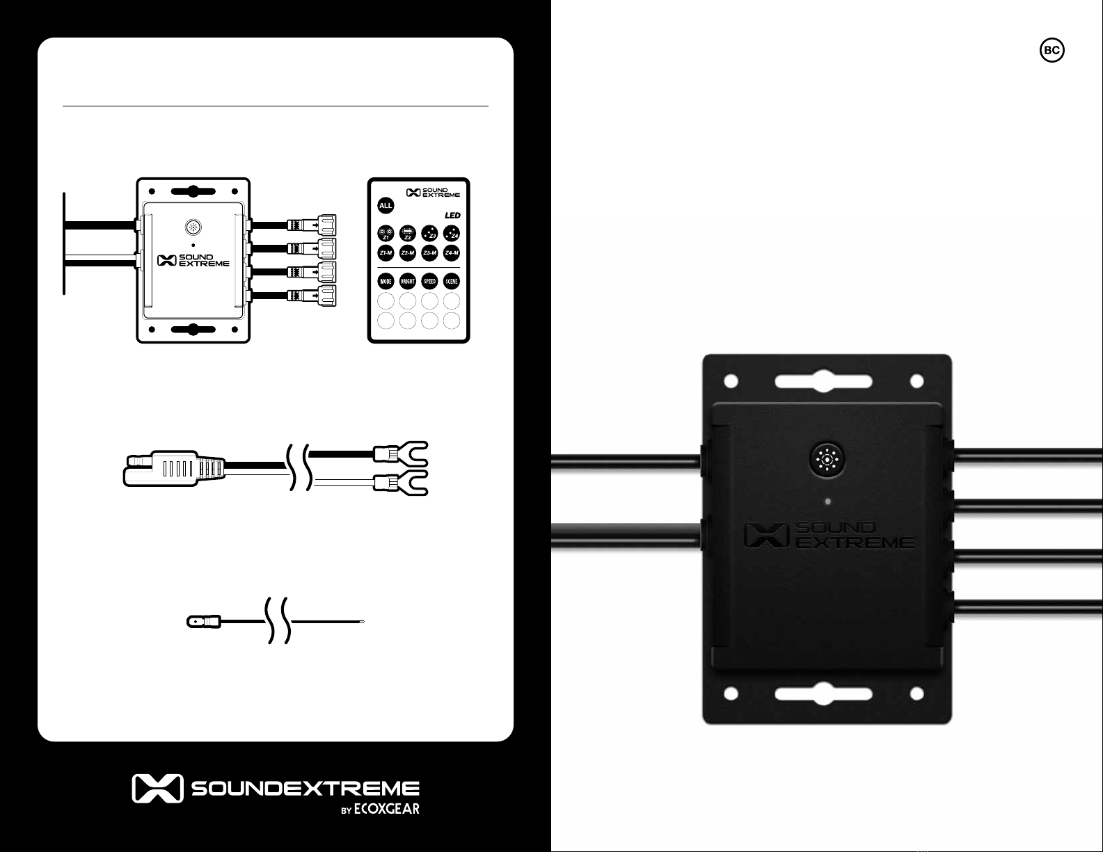
EcoxGear SOUNDEXTREME SEI-SELEDZ4 User manual

1
ExtremeController
Model: SEI-SELEDZ4
4-ZONE LED
CONTROLLER
User Guide
What’s in the Box
ExtremeController RF Remote Control
Remote Turn-On Extension Cable (Dark Blue) – 10 ft long
SAE Power Cable – 8 ft long

3 4
or a technician. Incorrect connections to your vehicle may cause
your controller or your vehicle to malfunction. Please note that the
maximum voltage for these 4 Vehicle Signal Inputs is 12VDC.
· The ExtremeController can be controlled by the included RF
Remote or a free SoundExtreme Smartphone App available on the
Apple App Store and Google Play Store.
· The ExtremeController can support multiple types of
SoundExtreme LED products. All 4 Zones come preset to the
6′ ExtremeWhip. To optimize the LED light performance the first
time you use the controller, or you make LED Zone connection
changes after the initial set up, please use the SoundExtreme
Smartphone App to choose the LEDCast product that is
connected to each Zone.
· The ExtremeController Music Modes work with ECOXGEAR or
SoundExtreme products with EcoCast wireless capability. When
an LED Zone output is set to Music Mode, the controller needs to
wirelessly connect to an EcoCast-enabled audio product.
· Do NOT make modifications to the ExtremeController LED
connectors or try to connect this product to other manufacturers’
LED products. It may cause permanent damage to the product
and VOID THE PRODUCT WARRANTY.
· Please read the User Guide before installation and use.
· The ExtremeController is compatible with the ECOXGEAR
audio and LED lighting EcoSystem, which includes LEDCast and
EcoCast Innovations. Look for the LEDCast and EcoCast logos on
the growing family of ECOXGEAR and SoundExtreme audio and
lighting solutions.
· The ExtremeController has four Zone LED Control Outputs.
Each Zone supports a maximum power output of 5A. Thus,
the total current consumption on the power supply to the
ExtremeController depends on how many LEDs are connected
to the controller. The maximum current draw is 20A if four 5A units
are connected to the controller AND are all lit up at the same time.
· Please refer to specifications of your SoundExtreme LED
product when you analyze the current-draw requirements of
your power supply.
· The voltage for the power input is +12VDC. You need to connect
to a 12VDC power supply. If your vehicle battery power is not 12V
(e.g., 24V, 36V, or 48V), you will need a DC-DC voltage converter
with 12V output (e.g. a 48V-to-12V converter). Connecting the
ExtremeController directly to higher voltages will cause damage
to the controller and VOID THE PRODUCT WARRANTY.
· The ExtremeController has a Remote Turn-On Input feature; this is
to ensure that the controller is completely powered o (no battery
consumption) when your vehicle is not in use. When the input has a
signal between 12V to 56V, the controller will turn on. When there is
no input voltage, the controller will turn o. In general, this Remote
Turn-On signal comes from the vehicle ignition switch.
· The ExtremeController has 4 Vehicle Signal Inputs (left turn,
right turn, brake, and reverse). When you connect the controller
to these inputs, only LED products that are connected to Zones
3 and 4 will be aected. If you are not sure where these signal
wires are located on your vehicle, consult your vehicle’s manual
ImportantImportant

5 6
ExtremeController Layout Button & Connectors
ExtremeController OverviewExtremeController Overview
Power Input Connector: Power-In SAE Connector (+12V and
GND), Remote Turn-On Wire (Dark Blue).
· The Power-In SAE cable has an in-line 25 Amp Fuse Holder.
· Also included are an 8ft SAE Power Cable and a 10ft Remote
Turn-On Extension Cable (Dark Blue).
Vehicle Signal Input Connectors: Connect to the vehicle for
left turn, right turn, brake, and reverse lighting integration. (This
connection is optional; however, you won’t be able to use the
Vehicle Signaling Features on your LED product without it.)
Multifunction Button: The Button has 3 functions.
1. Short-Press: Re-enable EcoCast audio pairing for LED
Music Mode.
Zone 1: LED Control
Output Connector
Zone 3: LED Control
Output Connector (Left)
Power Inputs:
12V Power-In SAE Connector,
Remote Turn-On Wire (Dark Blue)
Vehicle Signal Input
Connectors: Left
Turn, Right Turn,
Brake, Reverse
Zone 2: LED Control
Output Connector
Zone 4: LED Control
Output Connector (Right)
Connection Status
LED Indicator
Multifunction
Button
12V Power-In
SAE Connector
8ft Power Cable Fuse Holder
Vehicle Signal Input Connectors: Left
Turn, Right Turn, Brake, Reverse
Remote
Turn-On Wire
10ft Remote Turn-On
Extension Cable

7 8
ExtremeController Overview
2. Double-Click: Enable RF Remote Control pairing.
· The included Remote Control already comes paired and is
automatically connected to the ExtremeController.
· This feature is meant to be used if the connection is lost or a
replacement Remote Control is purchased.
3. Press and Hold for 3 seconds: Clears the EcoCast pairing records.
Connection Status LED Indicator: The LED indicates 3 possible
Connection Statuses.
1. Flashing Blue: The ExtremeController is in Remote Control
Pairing Mode.
2. Flashing Green: The ExtremeController is searching for an
EcoCast Transmitting device to pair and connect to.
3. Solid Green: The ExtremeController is connected to an EcoCast
Transmitting device.
LED Control Output Connectors: Connect SoundExtreme LED
products to each of the 4 Zone Control Outputs.
· All 4 Zone Outputs have the same electric specifications.
· Only Zones 3 and 4 integrate with the Vehicle Signal Inputs,
allowing the connected LEDs to function as enhanced brake,
reverse, and turn signal lights.
LED Control Output Connectors
Connecting to 12VDC Power Supply
The ExtremeController does not have an internal battery. It must
be connected to an external 12VDC power supply to function.
When you install the ExtremeController to a battery or a voltage
regulator on a golf cart, a boat, a quad bike, a UTV, or another vehicle,
you need to make sure that your vehicle battery or battery pack
terminal voltage is 12VDC. If the battery terminal voltage is not 12V,
you will need a DC–DC converter with output 12V. Connecting the
ExtremeController to a non-12VDC power source will lead to a
malfunction or damage to the controller.
Note: Besides the power supply, the ExtremeController relies on the
Remote Turn-On Signal Input to turn on and o. Refer to Connecting
the Remote Turn-On Input Wire to a Switch for more details.
Installation: 12V Power-In SAE Connector
1. Attach the 8ft Power Cable to the 12V Power-In SAE Connector.
Use Caution: Do NOT connect to 12V Battery if the Power In
SAE Connector is wet. Contact may cause electric shock and
injury if wet.
2. Remove the 25 Amp Blade Fuse from the Fuse Holder.
Installation and Wiring

9 10
Use Caution: Do NOT remove
Fuse if the Fuse Holder is wet. An
improperly fitted cap may cause
electric shock and injury if wet.
3. To close properly, push firmly to
be sure the cap snaps into place.
4. Next follow either the Gas
Vehicle or Electric Vehicle
Installation instructions.
Installation: Gas Vehicle
1. Loosen the bolts on the
battery terminals.
Use Caution: Do NOT attempt
to loosen bolts if battery is wet.
Contact may cause electric shock
and injury if wet.
2. Connect the BLACK wire to the
BLACK, negative terminal, then
the RED wire to the RED, positive
terminal. Unit will not work correctly
and may be damaged if wires are
not correctly attached.
3. Tighten the bolts on the battery
terminals until the connectors are
held firmly in place.
4. Return the 25 Amp Blade Fuse into
the Fuse Holder and close the cap.
Tip: Use zip ties to gather any excess
wires, and secure them so that they are
not dangling, loosely.
Installation and Wiring
Loosen Bolts
Black Cable Red Cable
Tighten Bolts
Installation and Wiring
Installation: Electric Vehicle
1. Switch your vehicle to Tow
mode, if available.
2. Wire the BLACK wire to the
GROUND on output of the
DC-DC Converter.
3. Wire the RED wire to the
POSITIVE (+) post on the output
of the DC-DC converter. Unit
will not work correctly and may
be damaged if wires are not
correctly attached.
4. Return the 25 Amp Blade Fuse into
the Fuse Holder and close the cap.
Use Caution: Do NOT connect to
DC-DC converter if the 8ft Power
Cable or the Power-In SAE Connector
are wet. Contact may cause electric
shock and injury if wet.
Tip: Use zip ties to gather any
excess wires, and secure them so
that they are not dangling, loosely.
Connecting the Remote Turn-On Input Wire to a Switch
Besides the 12V power supply, the ExtremeController relies on the
Remote Turn-On Signal Input to turn on and power o. The input
voltage range to turn on is 12V to 56V. When the input voltage is 0, it
will power o the controller.
You will need to connect the (Dark Blue) Remote Turn-On Wire to
the vehicle ignition switch with the supplied (Dark Blue) Remote
Turn-On Extension Cable. If you are not able to connect it to your
vehicle ignition switch, connect this input to a rocker switch (not
Black Cable Red Cable

11 12
included), then connect the rocker switch to a 12V to 56V power
supply on your vehicle or to a switch accessory panel.
WARNING: The RF Remote Control does NOT turn o the
ExtremeController. The Remote only turns o the connected LEDs.
To prevent draining your vehicle’s battery, you must turn the vehicle
ignition o or the rocker switch o.
Connecting to a Switch
To connect the ExtremeController to your vehicle’s ignition switch
or a rocker switch, follow the steps below:
Installation and Wiring
1. Connect the (Dark Blue) Remote Turn-On Wire to the
Accessories terminal of your switch with the supplied (Dark
Blue) Remote Turn-On Extension Cable.
2. Connect the Power terminal of your switch to your vehicle’s
(12V - 56V) power supply terminal with a cable that comes
with your switch.
3. Once the connections are completed, the ExtremeController will
turn on or o when the switch is turned on or o.
Connecting to a Power Panel or Switch Panel
If your vehicle has an accessory power panel or switch panel, you
can use a connection on the panel to turn the ExtremeController on
or o with the following steps:
1. Find a terminal on the panel that has 12VDC - 56VDC output when
the switch is on and 0VDC output when the switch is o.
Installation and Wiring
Accessories
Remote Turn-On Wire +
10ft Extension Cable
SwitchVehicle
Battery
+12V Power
12V Power-In SAE Connector +
8ft Power Cable
Accessories
Power
Ground

13 14
2. Connect the (Dark Blue) Remote Turn-On Wire to the switch
terminal with the supplied (Dark Blue) Remote Turn-On
Extension Cable.
Installation and Wiring
GND
+12V Power
Vehicle Power /
Switch Panel
Switch Terminal
Switch On: 12VDC
Switch O: 0VDC
Installation and Wiring
3. Once the connection is completed, when the vehicle is on, the
ExtremeController will turn on or o when the panel is turned
on or o.
Recommendation: If you are not familiar with all of the switch
connections on the panel, consult your switch accessory panel’s
manual or a technician. Incorrect connections to your panel may
cause your controller or your panel to malfunction.
Connecting LEDCast-Enabled Products
1. Once the 12V Power and Remote-Turn On Input connections
have been made, turn on the vehicle ignition switch (or the rocker
switch). The Connection Status LED Indicator will flash Blue,
indicating a successful power connection. If not, check the
ExtremeController wirings.
2. Now, turn o the vehicle ignition switch (or the rocker switch) to
turn o the ExtremeController. To avoid potential damage to the
product, you MUST disconnect the SAE Power Cable from the
controller before connecting a SoundExtreme LED product to it.
3. Connect LEDCast-enabled products to any of the 4 LED Control
Outputs. The following is an example configuration by Zone:
· Zone 1: ExtremeStrip – Roof.
· Zone 2: ExtremeStrip – Underglow.
· Zone 3 (left): ExtremeWhip installed on the vehicle’s left side.
· Zone 4 (right): ExtremeWhip installed on the vehicle’s right side.
Run the LED control cable from the LEDCast-enabled product
to the ExtremeController, making sure the cable does NOT
touch any moving parts on the vehicle. If the cable is longer than
required, do NOT cut the cable and reconnect. Instead, wrap the
extra length on your vehicle and fasten the cable with zip ties.
Please ensure the cable does NOT touch or drag on the ground
AND is safely secured to prevent it from coming into contact with
any moving parts.

15 16
4. To connect the cables connect the 3-pin female connector on the
control cable to the 3-pin male connector on a LEDCast-enabled
product. Align the arrow on both connectors, push in and screw
the nut cap on the female connector.
Connect the 3-pin male connector on the control cable to the LED
control output 3-pin female connector on the ExtremeController.
5. Optional: Integrate with the Vehicle Signal Inputs.
If you are familiar with all of your vehicle’s signal input connections,
you can connect the Vehicle Signal Input Control Connectors to
your vehicle’s turn, brake, and reverse wires (connection cables
between the ExtremeController and your vehicle signal are not
included) to add the Street Mode function to Zone 3 and 4.
· Pink Wire: Reverse Signal
· Orange Wire: Brake Signal
· Green Wire: Left Turn Signal
· Blue Wire: Right Turn Signal
Recommendation: If you are not sure where these signal wires
are located on your vehicle, consult your vehicle’s manual or a
technician. Incorrect connections to your vehicle may cause your
controller or your vehicle to malfunction.
Installation and Wiring Installation and Wiring
IMPORTANT: After you complete all the wiring and turn on the
ExtremeController for the first time, test for proper wiring and
function as follows:
· Turn vehicle’s left turn signal on: LED’s connected to Zone 3 will
flash Yellow.
· Turn vehicle’s right turn signal on: LED’s connected to Zone 4 will
flash Yellow.
· Press the vehicle’s brake: LED’s connected to Zone 3 and 4 will
shine Red.
· Carefully put your vehicle in reverse: LED’s connected to Zone 3
and 4 will shine White.
6. Wiring is now complete. When power is provided to the
ExtremeController, use the included RF Remote Control or
SoundExtreme Smartphone App to control the system.

17 18
Zones
A Zone corresponds to all of the
LED lights that are connected
directly to one physical LED Control Output on the
ExtremeController. When you change a Zone status (On/
O, Mode, etc.), the LEDs connected to that Zone will change
accordingly. You can control one Zone or multiple Zones at a time.
Modes
There are 3 LED Mode categories, totaling in 44 Modes supported
by the RF Remote. The SoundExtreme app can support many
more Color Modes.
1. Color Mode: Each Color Mode lights up the LEDs in a solid color.
There are 8 Color Buttons on the Remote Control: Red, Green,
Blue, White, Orange, Yellow, Cyan, and Purple. You can create a
custom color by utilizing the SoundExtreme Smartphone App.
2. Party Mode: There are 20 preset Party Modes accessible via the
Remote Control and SoundExtreme Smartphone App. The app
allows you to customize each of the 20 Party Modes, allowing for
nearly unlimited color, cascading, and LED chasing options.
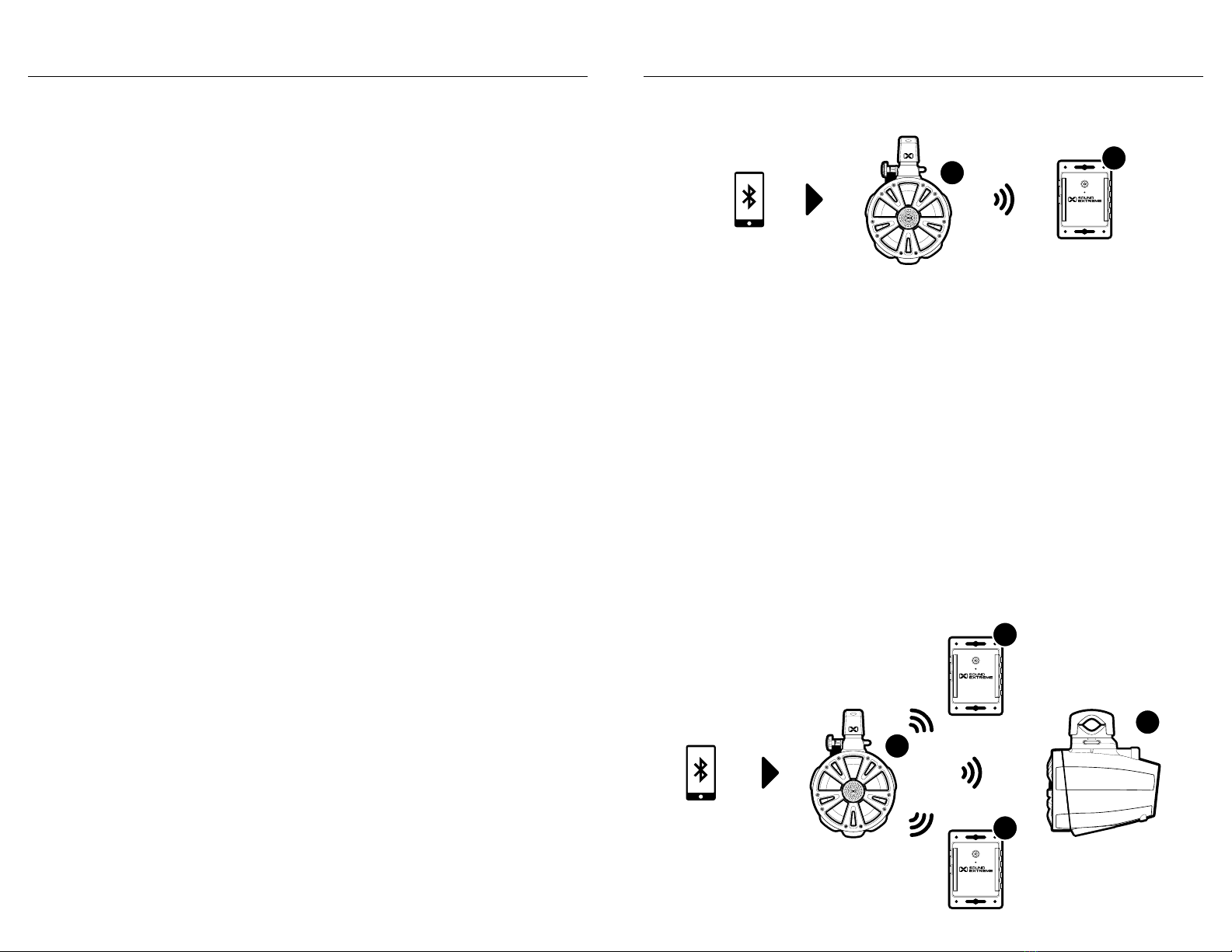
3. Music Mode: There are 16 Music Modes accessible via the
Remote Control and SoundExtreme Smartphone App. In
order to sync with the music, the ExtremeController must be
wirelessly connected to an EcoCast-enabled ECOXGEAR or
SoundExtreme audio product. Refer to EcoCast for Music Mode
for more information.
Scene
A Scene is programed via the SoundExtreme Smartphone App.
You can customize each Zone into a Scene (a preset). Setting
the Scenes on the app allows a 1-button press to bring up your
desired custom settings for all of the LED products connected to
the ExtremeController.
Lighting Control Concepts
The ExtremeController supports 6 lighting Scenes. Scenes 1-5
are user customizable and programmable. The 6th scene, Street
Mode, is for special use and cannot be modified. The default Scene
settings are:
· Scene 1: Orange for all 4 Zones.
· Scene 2: Flowing colors for all 4 Zones.
· Scene 3: Patriot 1 for all 4 Zones.
· Scene 4: Fading colors for all 4 Zones.
· Scene 5: Christmas for all 4 Zones.
· Scene 6: Street Mode – Turns all LED lights o but keeps the
controller powered on so Zones 3 and 4 will still function as
enhanced brake, reverse, and turn signal lights.
Street Mode: Zone 3 and 4 Vehicle Signaling
If you have Integrated the ExtremeController with the Vehicle’s Signal
Inputs, you can use the Street Mode function.
Under normal operations, when all 4 Zones are turned o, the vehicle
signaling in Zones 3 and 4 automatically enters O Mode.
When LEDs in any of the 4 Zones are turned on, as soon as the
controller has a vehicle’s signal input, Zone 3 and 4 LEDs will light
up accordingly. The LEDs will resume their original status (an LED
Mode) once the vehicle signal input is gone.
You can also use the RF Remote Control to turn the LED lights in all
4 Zones on or o (when the controller has a vehicle’s Remote Turn-
On Signal Input). Simply press the ALL Button to turn the LEDs in all
4 Zones on or o. When the LEDs in all 4 Zones are turned o, the
controller has the following two functions:
· O Mode: When the LEDs in all 4 Zones are turned o, the
controller disables the vehicle signaling to the LEDs in Zones 3 and
4, i.e. Zone 3 and 4 LEDs will not light up, even if there is a vehicle
Lighting Control Concepts

19 20
signal input. This O Mode is for users who do not want their LEDs
to light up while they are driving.
· Street Mode: When the controller is in this Mode, all 4 Zone
LEDs are also turned o. However, as soon as the controller
has a vehicle’s signal input, the LEDs in Zone 3 and 4 will light up
accordingly. The LEDs will turn o once the vehicle signal input
is gone.
To enable Street Mode, press the Scene Button on the Remote
to cycle through to the 6th Scene or use the SoundExtreme
Smartphone App and select Scene 6 – Street Mode.
When the ExtremeController enters Street Mode, each of the LEDs
in all 4 Zones will briefly light up Blue in ascending order to indicate
that Street Mode is active.
When the ExtremeController is in Street Mode, any Mode change
to a Zone (e.g. change Zone 1 Color) or Scene change will bring the
controller out of Street Mode and into the selected setting.
When the controller exits Street Mode, each of the LEDs in all 4
Zones will briefly light up Blue in descending order.
EcoCast for Music Mode
The ExtremeController is compatible with the ECOXGEAR audio
and LED lighting EcoSystem, which includes LEDCast and EcoCast
Innovations. Look for the LEDCast and EcoCast logos on the
growing family of ECOXGEAR and SoundExtreme audio and lighting
solutions. EcoCast-enabled audio products are designed to be
paired with one or more EcoCast-enabled products. Simply initiate
EcoCast Transmitting Mode in one SoundExtreme or ECOXGEAR
speaker and broadcast your music to one or more EcoCast-enabled
products in Receiving Mode. Once connected to your controller,
select a Music Mode to have all of your LED lights complement
the music.
Note: The ExtremeController is always in EcoCast Receiving Mode.
Lighting Control Concepts
1. Follow the Pairing a Bluetooth Device instructions in your
speaker’s user guide to connect it (Speaker A) to your Bluetooth
device. After your device is connected to Speaker A, you can
select a song to play.
2. Initiate EcoCast Transmitting Mode on Speaker A.
3. Power on your ExtremeController (Controller B). It will already
be in EcoCast Receiving Mode. The Connection Status LED
Indicator will flash Green.
4. Once the connection between the products is successful, the
Connection Status LED Indicator on Controller B will shine solid
Green. You can now select one of the 16 Music Modes with the
Remote Control or the SoundExtreme Smartphone App.
EcoCast: Additional Receiving Speakers and / or Controllers
EcoCast: Speaker to ExtremeController
Lighting Control Concepts
AB
A
C
B
D

21 22
Lighting Control Concepts
1. Power on the additional EcoCast-enabled products (Speaker C
and Controller D) and initiate EcoCast Receiving Mode in Speaker
C(Controller D will already be in EcoCast Receiving Mode). The
Connection Status LED Indicator on Controller D will flash Green.
2. Reinitiate EcoCast pairing on Speaker A.
3. Once the connection between the speakers is successful, the
Connection Status LED Indicator on Controller D will shine solid
Green. You can now select one of the 16 Music Modes.
Notes:
· If all the speakers are turned o, then turned on, the speaker(s)
and controller(s) in EcoCast Receiving Mode (Speakers and
Controllers B, C, and D) will automatically re-connect to the
speaker in Transmitting Mode (Speaker A). If they are not
automatically re-connected, please follow the above steps.
· To clear pairing records on an ExtremeController, PRESS AND
HOLD for 3 seconds.
· If the ExtremeController is unable to pair and connect with the
speaker, re-enable the EcoCast pairing on the speaker, then
PRESS AND HOLD the ALL Button on the RF Remote Control to
enable EcoCast pairing on the controller.
· The EcoCast functionality is only available while using Bluetooth as
your Audio Source on legacy ECOXGEAR products at a maximum
range of 30 feet between speakers.
· While connecting the EcoCast-enabled products, make sure that
they are within a few feet of each other.
The RF Remote Control comes paired to the ExtremeController.
If the ExtremeController does not react when you press a button
on the Remote Control, check if the battery isolator (clear plastic
strip) on the Remote battery compartment is removed (pulled out)
completely. Then, power o and power on the ExtremeController.
When the Connection Status LED Indicator on the controller
flashes Blue, PRESS AND HOLD the Mode Button on the Remote
for 3 seconds. The Status LED Indicator will shine solid Green for
1 second, then flash Green, indicating a successful pair.
Basic Functions
1. Turn on the vehicle ignition switch (or the rocker switch) to power
on the ExtremeController.
2. Press the ALL Button to turn on the LEDs in all of the Zones. Each
of the LEDs will briefly light up Green in ascending order and then
shine solid Orange or a random color pattern.
3. If you don’t see the LEDs light up, as a test, short-press the Red
Button. The LEDs in all the Zones will shine solid Red.
Standby Button
Zone Buttons:
Z1 · · · Z4
Zone-Mode Buttons:
Z1-M · · · Z4-M
Common Buttons:
Mode, Scene,
Bright, Speed,
and Color
RF Remote Control

23 24
4. There are three ways to change the LED Mode:
· Short-press the Mode Button to cycle through the three LED
Mode categories for all the Zones.
· Short-press one of the 8 Color Buttons to light the LEDs in all the
Zones in the corresponding color.
· Short-press one of the Zone-Mode Buttons (Z1-M, Z2-M, Z3-M,
or Z4-M) to cycle through the three LED Mode categories for
only the corresponding Zone.
Note: There are 44 distinct LED Modes. Instead of using the Mode
Button to cycle through to a desired LED Mode, you can also use
the SoundExtreme Smartphone App to find a specific LED Mode.
5. To optimize the LED lighting performance the first time you
use the ExtremeController, or you change the LEDs physically
connected to a Zone, use the SoundExtreme Smartphone App
to select the LED product connected to each Zone. Refer to the
SoundExtreme Smartphone App instructions for more details.
6. If you have an ECOXGEAR speaker with EcoCast capability and
/ or a SoundExtreme speaker with LEDCast technology, you can
connect the ExtremeController to either product for Music Mode.
If the ExtremeController is unable to pair and connect with the
speaker, re-enable the EcoCast pairing on the speaker, then
PRESS AND HOLD the ALL Button on the RF Remote Control to
enable EcoCast pairing on the controller. Refer to the EcoCast for
Music Mode instructions for more details.
7. Short-press the Mode Button to cycle through the multiple
Music Modes.
· When no music is playing the LED will be dark. So, please play
music while changing Music Modes to review the various Music
Mode eects.
· There are 44 distinct LED Modes. Instead of using the Mode
Button to cycle through to a desired Music Mode, you can also
use the SoundExtreme Smartphone App to find a specific
Music Mode.
8. Short-press any of the 8 Color Buttons to change the colors in all
LED Zones.
Advanced Functions
You can also change the LED lighting eect in only 1 Zone at a time:
1. To activate the Zone you want to change, PRESS AND HOLD
the Zone Button. For example, press and hold the Z1 Button for 3
seconds. The LEDs in Zone 1 will flash Green twice, indicating that
Zone 1 is selected.
2. You can now PRESS AND HOLD any of the 8 Color Buttons, the
Bright Button, or the Speed Button for 2 seconds (instead of a
short-press) to modify the LEDs in the selected Zone.
3. To change another Zone, e.g. Zone 3, PRESS AND HOLD the Z3
Button. The LEDs on Zone 3 will flash Green twice, indicating that
Zone 3 is selected. Follow step 2 to modify the LEDs in Zone 3.
Note: Anytime you short-press a Common Button on the Remote,
it will change the LEDs on all Zones.
RF Remote Control RF Remote Control

25 26
BUTTON ACTION FUNCTION
Short-Press Turn on / o the LEDs in all Zones.
Press and Hold
(for 3 seconds)
To enable EcoCast pairing.
Short-Press To turn on / o the Zone 1 LEDs.
Press and Hold
(for 3 seconds)
To select Zone 1.
Short-Press To turn on / o the Zone 2 LEDs.
Press and Hold
(for 3 seconds)
To select Zone 2.
Short-Press To turn on / o the Zone 3 LEDs.
Press and Hold
(for 3 seconds)
To select Zone 3.
Short-Press To turn on / o the Zone 4 LEDs.
Press and Hold
(for 3 seconds)
To select Zone 4.
NOTES
· When turned on, each of the LEDs will light up Green in ascending order. When
turned o, the LEDs light up Red in descending order.
· Does not turn o the ExtremeController. Only the vehicle ignition switch (or rocker
switch) can power o the controller.
· Refer to Zones, Modes, and Scenes. Note: If you want to turn all of the LED lights
o but still want Zones 3 and 4 to function as enhanced brake, reverse, and turn
signal lights, use Street Mode (Scene 6).
· The Button on the ExtremeController has the same Action / Function.
· When turned on, LEDs in Zone 1 will light up Green in ascending order. When
turned o, the LEDs light up Red in descending order.
· The LEDs in Zone 1 will flash Green twice, indicating that the (Bright, Speed, and
Color) Common Buttons will only apply to Zone 1.
· When turned on, LEDs in Zone 2 will light up Green in ascending order. When
turned o, the LEDs light up Red in descending order.
· The LEDs in Zone 2 will flash Green twice, indicating that the (Bright, Speed, and
Color) Common Buttons will only apply to Zone 2.
· When turned on, LEDs in Zone 3 will light up Green in ascending order. When
turned o, the LEDs light up Red in descending order.
· The LEDs in Zone 3 will flash Green twice, indicating that the (Bright, Speed, and
Color) Common Buttons will only apply to Zone 3.
· When turned on, LEDs in Zone 4 will light up Green in ascending order. When
turned o, the LEDs light up Red in descending order.
· The LEDs in Zone 4 will flash Green twice, indicating that the (Bright, Speed, and
Color) Common Buttons will only apply to Zone 4.
Remote Functions Overview Remote Functions Overview

27 28
BUTTON ACTION FUNCTION
Short-Press To cycle through the three LED
Mode categories for Zone 1.
Double-Click To cycle back to the previous LED
Mode for Zone 1.
Short-Press To cycle through the three LED
Mode categories for Zone 2.
Double-Click To cycle back to the previous LED
Mode for Zone 2.
Short-Press To cycle through the three LED
Mode categories for Zone 3.
Double-Click To cycle back to the previous LED
Mode for Zone 3.
Short-Press To cycle through the three LED
Mode categories for Zone 4.
Double-Click To cycle back to the previous LED
Mode for Zone 4.
Short-Press To cycle through the three LED
Mode categories for all the Zones.
Double-Click To cycle back to the previous LED
Mode for ALL Zones.
Press and Hold
(for 3 seconds)
To enter Pairing Mode with
the ExtremeController.
NOTES
· There are 44 distinct LED Modes: 8 Color Modes, 18 Party Modes, and 16 Music
Modes. You can also use the SoundExtreme Smartphone App to find a specific
LED Mode.
· The RF Remote Control comes paired to the ExtremeController. This feature is
meant to be used if the connection is lost or a replacement Remote is purchased.
Remote Functions Overview Remote Functions Overview

29 30
BUTTON ACTION FUNCTION
Short-Press To cycle through the 5 defined
Scenes for all the Zones.
Press and Hold
(for 3 seconds)
To set all Zones to shine Orange, at
100% brightness and 80% speed.
Short-Press To cycle through 5 levels of
Brightness for all the Zones.
Press and Hold
(for 2 seconds)
To cycle through 5 levels of
Brightness for the selected Zone.
Short-Press To cycle through 5 levels of Speed
for all the Zones.
Press and Hold
(for 2 seconds)
To cycle through 5 levels of Speed
for the selected Zone.
Short-Press To select the corresponding Color
for all the Zones.
Press and Hold
(for 2 seconds)
To select the corresponding Color
for the selected Zone.
NOTES
· Scene 6 (Street Mode) turns all the LED lights o but Zones 3 and 4 will still
function as enhanced brake, reverse, and turn signal lights.
· This feature is only available when one of the Zones has been selected via one of
the Zone Buttons. (Press and hold Z1, Z2, Z3, or Z4 for 3 seconds).
· This feature is only available when one of the Zones has been selected via one of
the Zone Buttons. (Press and hold Z1, Z2, Z3, or Z4 for 3 seconds).
· There are 8 Color Buttons on the Remote Control: Red, Green, Blue, White,
Orange, Yellow, Cyan, and Purple. You can also use the SoundExtreme
Smartphone App create a custom color.
· This feature is only available when one of the Zones has been selected via one of
the Zone Buttons. (Press and hold Z1, Z2, Z3, or Z4 for 3 seconds).
Remote Functions Overview Remote Functions Overview

31 32
The ExtremeController can be operated via the SoundExtreme
Smartphone App.
Download and Install
For iPhones, download the app from the following URL:
https://apps.apple.com/us/app/soundextreme/id1670708941
For Android phones, download the app from the following URL:
https://play.google.com/store/apps/details?id=com.cchip.ecoxgear
Alternatively, use the following QR Codes to download the
SoundExtreme Smartphone App.
iOS Android
App Overview
Password Secured: The app is password protected so others
cannot gain access and control your ExtremeController. The default
password is 0000.
Name Your Devices: You can change and customize the name
of your devices and Zones, such as Rear speakers, Soundbar,
Subwoofer, Cabin Lights, Underglows, Roof Lights, Whips, etc.
Set Up Modes: Use the app to set up the LED Mode for each of
the 4 Zones on your ExtremeController. You can also change the
Brightness and Speed.
SoundExtreme App SoundExtreme App
Create and save Scenes: A Scene is a preprogrammed light show
that you can save for later quick-access. We have created 5 default
Scenes that are fully customizable and programmable.
Set Up a Group: Create and set up a group of devices (multiple
ExtremeControllers, or other SoundExtreme products with LEDCast
built-in). This will allow all the LED lights connected to dierent
devices to be controlled by the SoundExtreme Smartphone App at
the same time.
Bluetooth Low Energy: The SoundExtreme Smartphone App
relies on a BLE (Bluetooth Low Energy) connection between your
phone and the ExtremeController. Make sure you turn on Bluetooth
on your smartphone.
Initial App Connection
and Device & LED Setup
1. Launch the SoundExtreme
App on your smartphone or
other BLE-enabled device.
2. On the SoundExtreme App
homepage, tap Refresh List.

33 34
3. If your ExtremeController
is powered on, it will show
up as 4 Zone Controller on
the app’s Connect Device
screen. Tap the device name
on the screen. A checkmark
will appear on the right. Tap
the Connect button.
4. A dialog window will
popup asking you to
enter a password. The
ExtremeController default
password is 0000.
5. If the app connects to
your ExtremeController
successfully, a popup
message will appear,
showing the Device & LED
Settings for the 4 Zones
on your controller and ask
you if you want to change
the settings. On the bottom
of the message there is a
checkbox to ask if you want
this message to be displayed
the next time the app
connects to your controller.
6. If you choose to change
the Device & LED
Settings, the app will bring
you to the Device & LED
Set Up menu for you to
choose the LED device
from the pull-down list.
SoundExtreme App SoundExtreme App
7. Once the Device & LED
Settings are completed,
the app will bring you to
the Device screen.
8. Select your controller. It
will take you to the Scene
Screen. There are 6
predefined Scenes on the
controller. You can turn
on one of first 5 Scenes
to light up the LEDs. For
example, click the On
/ O button at the right
for Scene 1, the Speaker
LEDs will light up Orange,
which is the LED lighting
mode defined for Scene 1.

35 36
Set Up Zones
1. Select your
ExtremeController on the
Device list, and the app will
bring you to the Zone screen.
2. Tap one of the 4 Zones, and
you will go to the Zone LED
Mode Settings screen. There
are 3 tabs: Color, Party, and
Music, which allow you to
select a solid Color, a Party
Mode, or a Music Mode.
SoundExtreme App SoundExtreme App
· When you choose a Mode,
the LEDs connected to the
Zone you selected will light
up accordingly, giving you
a preview.
· If you tap the Save button
on the screen, the app will
save your setting for the
selected Zone.
· If you tap the Cancel button
or exit the LED Mode Settings
screen, your Mode selection
will not be saved and LEDs
connected to that Zone
will display the previously
selected LED Mode.

37 38
3. After you set up the Modes
for each of the Zones, the
controller setup is complete.
SoundExtreme App SoundExtreme App
Set Up Scenes
1. Select your
ExtremeController on the
Device list, and the app will
bring you to the Zone screen.
Tap the Scene tab. The app
will show 6 pre-defined
scenes on your controller.
As previously mentioned
in Zones, Modes, and
Scenes, Scene 6 is designed
for Street Mode and not
editable. Street Mode turns
all the lights o but keeps the
controller on. If you have the
controller connected to your
vehicle’s turn signals, brakes
and / or reverse wires, the
connected LED devices in
Zones 3 and 4 will still light up
when applicable.
2. You can change a Scene’s
LED settings by selecting
any of the first 5 Scenes.
When you select the
Scene you will go to the
LED Mode Setting screen.
You can use the same
procedure as in the Set Up
Zones section to set up
each Zone and save the
Scene’s new LED settings.

39 40
SoundExtreme App SoundExtreme App
3. After you set up LED
Modes for all the Zones,
the setup is complete for
the selected Scene.
Change Password
To add extra security, you
can change the default
password of 0000 to your
desired 4-digit numeric
password. Please note that
the password is stored in your
ExtremeController, not the
SoundExtreme app. So, after
you change the password,
please make a note in case
you forget your password.
The password won’t be
reset by reinstalling the
app or changing to another
smartphone. The only way
to reset your password is to
conduct a factory reset on
your ExtremeController.
1. Select the Menu Icon
at the top-right corner of
the screen.
2. Select Device Password
from the menu.
3. Once at the Device
Password screen, select
the device that you want to
change the password to.
4. Enter the current
password, the new
password, and re-enter
the new password. Then
tap the Confirm button.
5. If the change is successfully
saved, the app will display a
confirmation message.
This is a one-time event. You
do not have to enter in your
password every time you
launch the app, as your app will
remember your password.
Table of contents
Popular Controllers manuals by other brands

Linak
Linak TECHLINE LA25 Connection diagram

High End Systems
High End Systems Universal Controller User manual addendum

Mitsubishi
Mitsubishi FX3U-232ADP(-MB) installation manual

Gossen MetraWatt
Gossen MetraWatt R2600 operating instructions

3M
3M Touch Screen Controller RX182 reference guide

TELEVAC
TELEVAC Compact 2A instruction manual