ECR International Argo ARH-1 User manual

Manufactured by:
ECR International Inc.
2201 Dwyer Avenue, Utica, NY 13501
Tel. 800 325 5479
www.ecrinternational.com
PN 240005131 REV. E [11/15/2021]
HYDRO-AIR ZONING
CONTROLS
ARH-1, ARH-2, ARH-3
ARH-1
ARH-2

2
PN 240005131 Rev. E [11/15/2021]
ARGO HYDRO-AIR ZONING CONTROLS
TABLE OF CONTENTS
WARNINGS AND SAFETY SYMBOLS
IMPORTANT: THIS MANUAL MUST BE KEPT FOR FUTURE REFERENCE!!
Warnings and Safety Symbols ......................................................................................2
Introduction .................................................................................................................2
Product Description......................................................................................................2
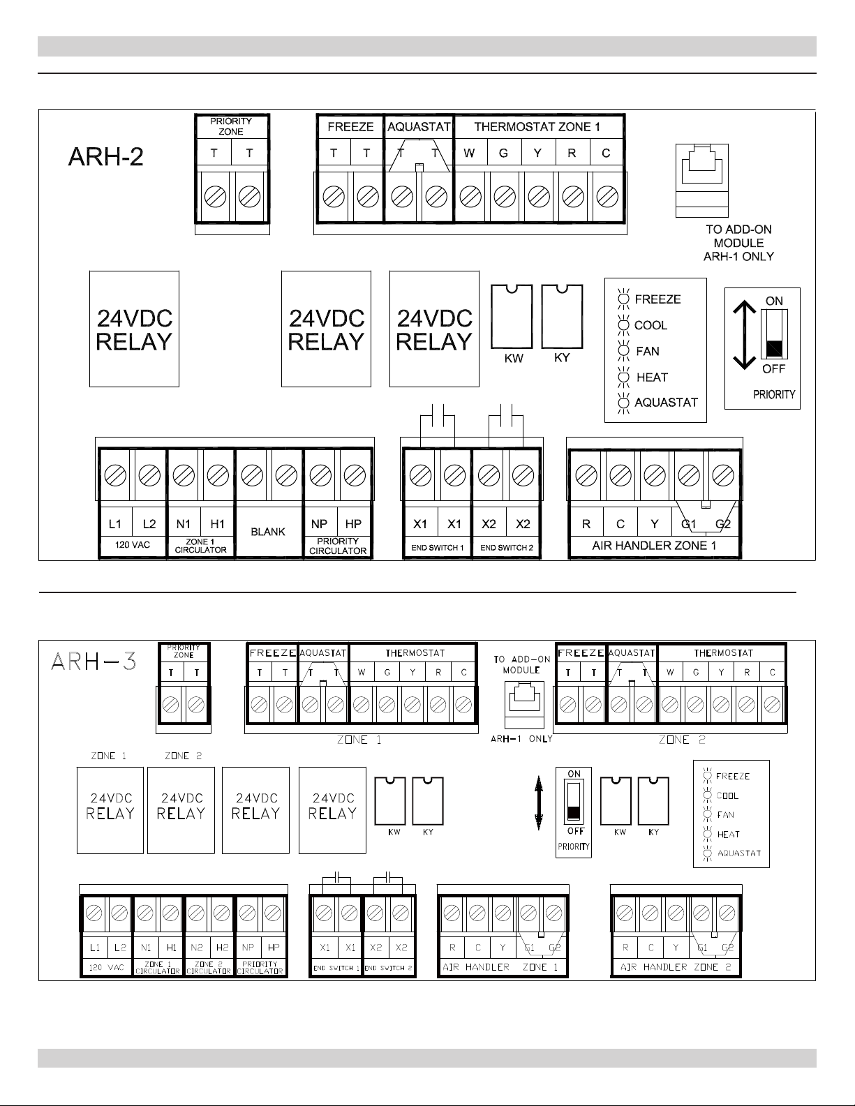
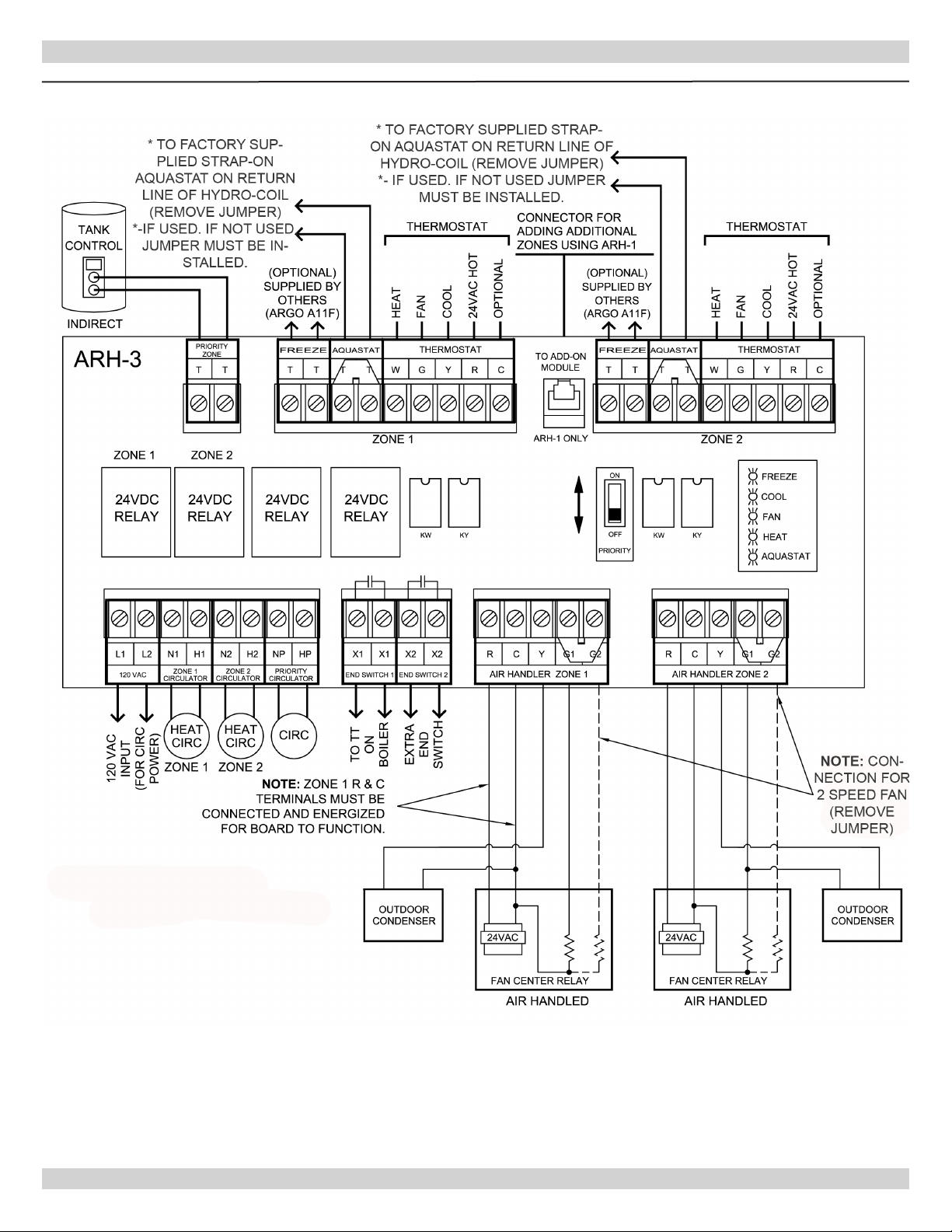
ARH Control Board Diagrams........................................................................................4
Mounting Instructions ..................................................................................................5
Electrical Specications & Wiring .................................................................................5
Sequence of Operation .................................................................................................6
Terminal Descriptions ..................................................................................................6
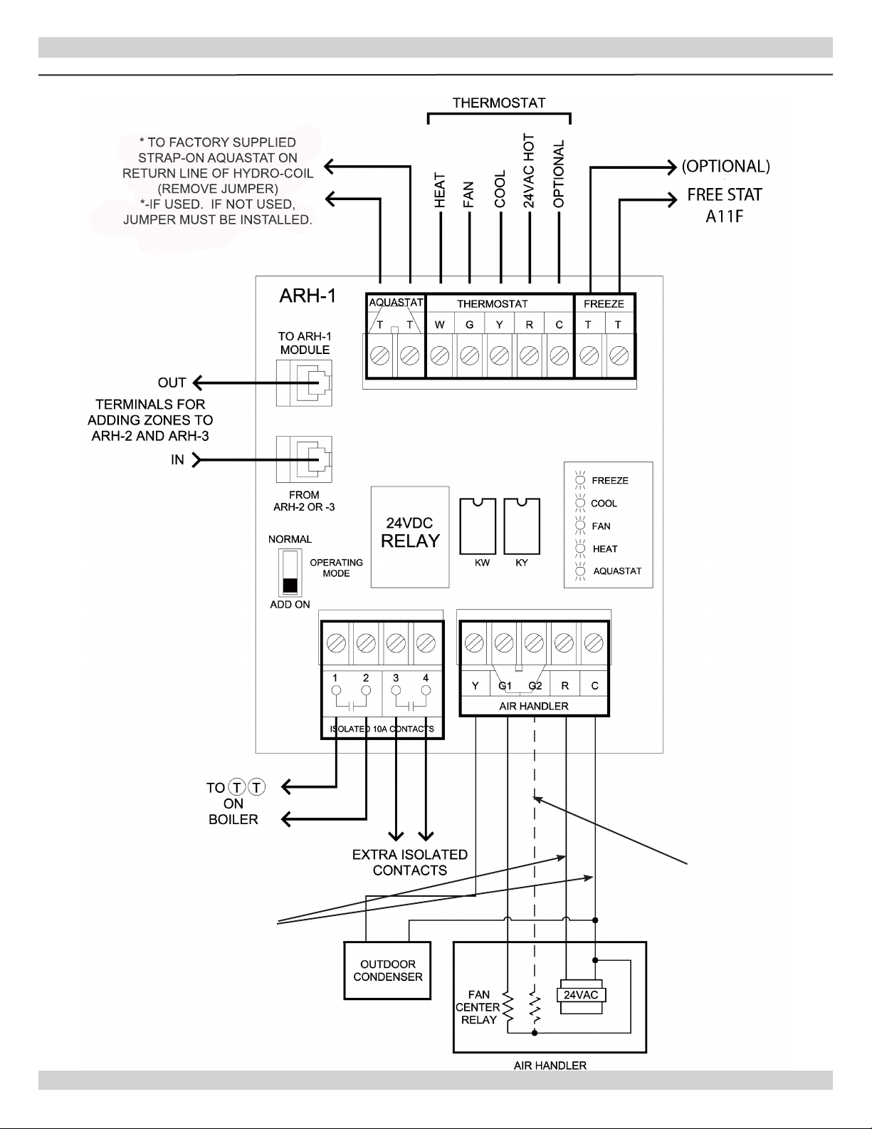
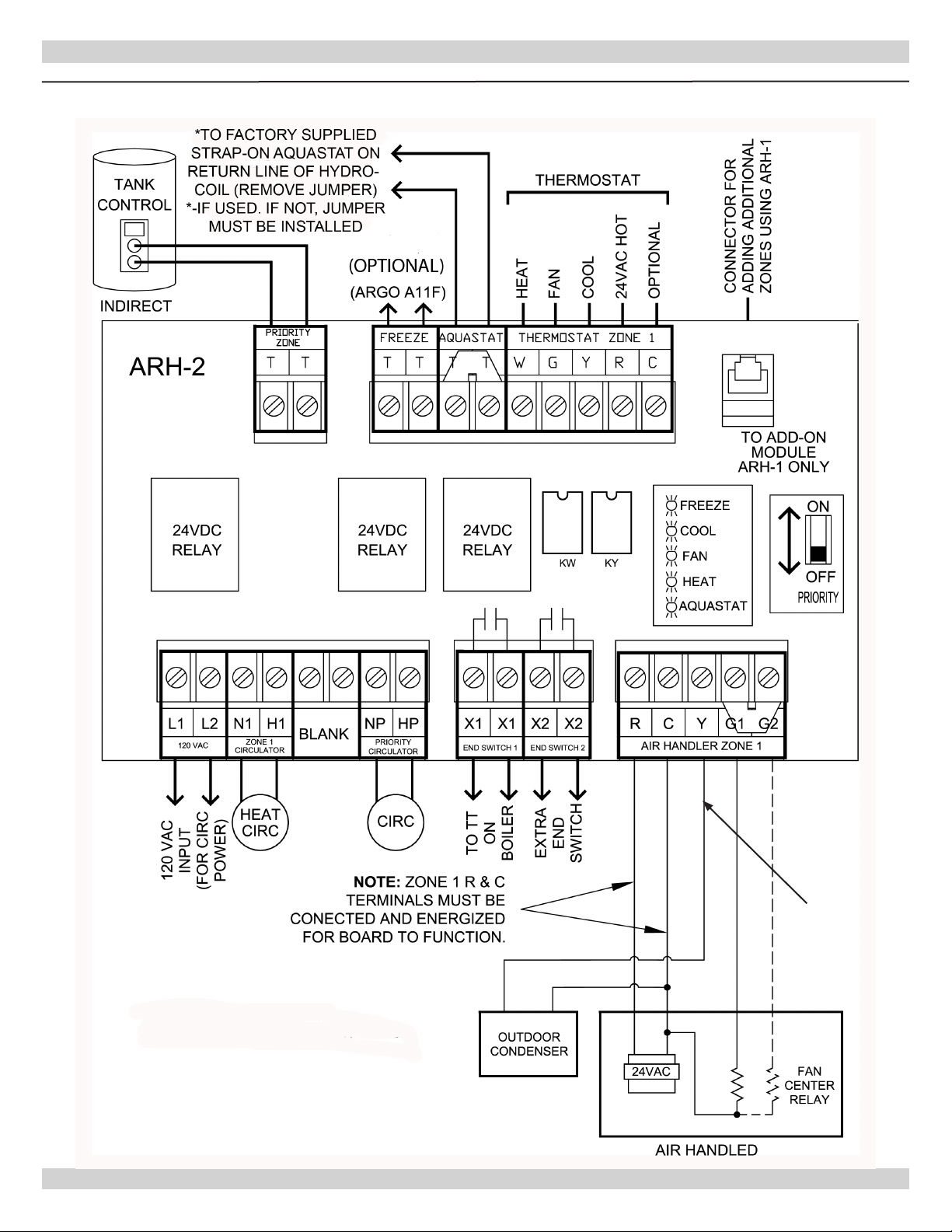
Wiring Diagram Applications ........................................................................................7
Replacement Parts .....................................................................................................11
Technical Support.......................................................................................................11
INTRODUCTION
This manual is intended to familiarize the installer
and user of the Argo ARH Series of Controls with their
installation and operation to assure normal trouble-
free operation.
Argo controls are designed and manufactured with
quality components for maximum life and durability
and require minimal service. To insure a satisfactory
installation, it is imperative that the instructions be
followed carefully before operating the control. Failure
to do so may result in breach of warranty.
PRODUCT DESCRIPTION
Argo Hydro-Air Zoning Controls provide the easiest
way to interface between the thermostat and air
handler. These dependable control relays will control
from 1 to 20 zones of heating/cooling and provide
priority switching for domestic hot water. Boiler and
A/C condenser wiring is virtually fool proof.
DANGER
Indicates a hazardous situation which, if not
avoided, WILL result in death or serious injury.
!
WARNING
Indicates a hazardous situation which, if not
avoided, could result in death or serious injury.
!
CAUTION
Indicates a hazardous situation which, if not
avoided, could result in minor or moderate injury.
!!
NOTICE
Indicates information which should be followed to
ensure proper installation and operation.
WARNING
Fire, Explosion, Asphyxiation, Electrical shock
hazard! Flooding will result in damages such as
electrical problems, corrosion, inoperative parts,
mold and other unforeseen issues which can
occur over time. Any equipment determined by
a professional as damaged by a ood, dened
as excess of water or other liquid, shall be
replaced. Failure to follow these directions will
result in a Hazardous Situation.
!

3
PN 240005131 Rev. E [11/15/2021]
ARH FEATURES AND BENEFITS
Choice of Three Models
– Single Zone/Expansion module (ARH-1)
– Two-Zone With Priority (ARH-2)
– Three-Zone with Priority (ARH-3)
All ARH Models have plug-in connections for easy expansion up to 20 zones.
Multiple Terminals for 2-speed air handlers
Built-In Air Handler “Freeze Protection”
Switch-able Priority for domestic hot water applications.
LED Diagnostic Lights for easy troubleshooting.
Includes Strap-On Bi-Metal Aquastat to prevent “cold air” circulation in heating mode.
100% Quality Controlled
All Controls Supported by Argo Technical/Support
ARH CONTROL BOARD DIAGRAMS
ARH -1

4
PN 240005131 Rev. E [11/15/2021]
ARH CONTROL BOARD DIAGRAMS
ARH-2
ARH-3

5
PN 240005131 Rev. E [11/15/2021]
MOUNTING INSTRUCTIONS
Mount Argo ARH Series Control vertically on a solid
wall or partition. Manufacturer recommends control
be mounted as close as possible to the device being
controlled, do not mount more than 75
feet away. Select a location that is easily accessible
for installation and service.
1.
Position the control and mark the mounting holes.
2.
Start screws (not provided) for the keyhole type
mounting holes in the upper corner(s). Tighten the
screws down to about ⅛” (3mm) from the surface.
The ARH-1 will require a screw to be installed in
the lower left hand corner after the control is hung
and leveled.
3.
Hang the control on the screws, position the case,
and start the bottom screws.
4.
Tighten all screws.
ELECTRICAL SPECIFICATIONS & WIRING
General Wiring Notice
All primary wiring must be 14 AWG minimum.
Torque terminal screws 6 to 7 inch pounds.
U.S.A. - National Electric Code and any oth-
er national, state, or local code requirements.
Wiring must be N.E.C. Class 1.
CANADA - C.S.A. C22.1 Canadian Electrical
Code Part 1 and any other national, provincial,
or local code requirements. Wiring must be
C.S.A. C22.1 C.E.C. Part 1.
Electrical Specications
Argo
Model
Number
Argo
Part
Number
Power Input
Ther-
mostat
Current
Supplied
Aquastat
ARH-1 Z181 24VAC/60Hz
.085A
3/8” to 3/4” Strap
on Bi-Metal
(ON at 118°F +
5%)
(OFF at 95°F +
5%)
ARH-2 Z179
24VAC/60Hz
120VAC/60Hz
for Circulator
Power
ARH-3 Z180
24VAC/60Hz
120VAC/60Hz
for Circulator
Power
NOTICE
To reduce possible transformer hum and relay
noise sometimes amplied by mounting surfaces
such as sheet metal, plasterboard, and similar
materials, place rubber or felt washers between
the case and mounting surface.
WARNING
Electrical shock hazard! Disconnect power
before installing or servicing. Failure to follow
these instructions could result in death or
serious injury.
!

6
PN 240005131 Rev. E [11/15/2021]
SEQUENCE OF OPERATION
When thermostat calls for heat, boiler end switch
closes, starting burner and energizing the heating
circulator. Fan will operate at low speed (G1) when
water temperature is above (118°F) the aquastat
setting at the Hydro-Coil.
If priority zone is actuated, priority circulator and
boiler end switch are energized. Heating circulator is
shut o and fan will operate at low speed (G1) until
water temperature drops below aquastat setting.
When thermostat calls for cooling, Argo Control
energizes outdoor condenser and starts the fan on
high speed (G2).
Optional Freeze Protection for Hydro-Coil: When
Freeze Terminals (TT) are shorted together as with
SPST actuator, heating zone circulator will operate to
circulate water through the Hydro-Coil.
For additional zones, use telephone connector to ARH-
1 module. Up to 20 Air Handler Zones can be “Daisy
Chained” together.
TERMINAL DESCRIPTIONS
Thermostat
W - Heat Switched Leg
G - Fan Switching Leg
Y - Cool Switching Leg
R - 24VAC Hot
C - 24VAC Common (Optional for use on ther-
mostats requiring common leg)
Aquastat
TT- Connect to factory supplied strap-on aquastat
(118°F) at Hydro-Coil. These terminals must be
closed for fan to operate in Heating Mode. Install a
jumper if no aquastat is used.
Freeze
TT- Optional freeze protection (Argo A11F) when
(TT) is connected to aquastat at Hydro-Coil.
When closed, these terminals start the heating
circulator, but not the fan. Using an SPST aqua-
stat that closes when temperature falls to 40°F
with a 5°F dierential (Honeywell L4080B), is
recommended.
Boiler End Switch
X1X1 - Connect to TT terminal on boiler
X2X2 - Extra End Switch
Air Handler
Y - Cooling Relay (Condenser)
G1 - Heat Fan Center Relay (Low Speed)
G2 - Cool Fan Center Relay (High Speed)
R - 24VAC Hot used to switch all functions.
C - 24VAC Common used to power fan control.
NOTICE
Note: A single Speed Fan requires Jumper to be
installed between G1 and G2.

7
PN 240005131 Rev. E [11/15/2021]
WIRING DIAGRAM APPLICATIONS
ARH-1 SINGLE ZONE HYDRO-AIR CONTROL INSTRUCTIONS
* TO FACTORY SUPPLIED
STRAP-ON AQUASTAT ON
RETURN LINE OF HYDRO-COIL
(REMOVE JUMPER)
*-IF USED. IF NOT USED,
JUMPER MUST BE INSTALLED.
Note: Connection
for 2 Speed Fan
(Remove Jumper)
(G1/G2)
Note: Zone 1 R & C terminals
must be connected and energized
for board to function.

8
PN 240005131 Rev. E [11/15/2021]
WIRING DIAGRAM APPLICATIONS
ARH-2 TWO ZONE HYDRO-AIR CONTROL INSTRUCTION (1 AIR HANDLER AND 1 PRIORITY ZONE)
NOTE:
CONNECTION
FOR 2 SPEED FAN
(REMOVE JUMPER)

9
PN 240005131 Rev. E [11/15/2021]
WIRING DIAGRAM APPLICATIONS
ARH-3 THREE ZONE HYDRO-AIR CONTROL INSTRUCTION (2 AIR HANDLER AND 1 PRIORITY ZONE)

10
PN 240005131 Rev. E [11/15/2021]
CONTROL EXPANSION APPLICATIONS
Wiring Diagram for Adding ARH-1 TO ARH-2 OR ARH-3

11
PN 240005131 Rev. E [11/15/2021]
REPLACEMENT PARTS
Replacement Parts
Part Description Argo Part Number
Relay 24VDC Coil R35DC
Snap on Aquastat (118° F) A10
18” Expansion Cable C1
Freeze Stat Aquastat (40°F) A11F
TECHNICAL SUPPORT
For technical support on this and all Argo products, please contact ECR International Technical Service
at 1-800-325-5479. Please have your model number available when calling.
Information Needed When Calling
Model Number
Installation Date
Installer

All specications subject to change without notice.
©2021 ECR International, Inc.
2201 Dwyer Avenue, Utica, NY 13501
Tel. 800 325 5479
www.ecrinternational.com
This manual suits for next models
2
Table of contents