ECRM Mako 8 CTP Manual

MAKO 8 CTP/
Operator Guide
NEWS extra

Mako 8 CTP / NEWS extra
Operator Guide
This guide reflects Mako 8 CTP/NEWS extra systems as of March 2005
© copyright ECRM Incorporated 2005
For additional copies of this guide contact:
ECRM Order Processing
554 Clark Road
Tewksbury, MA 01876
Phone No. (US) - (+1) 978-851-0207 — Fax (US) - (+1) 978-851-7016
Phone No. (UK) - (+44) 1923-218255 — Fax (UK) (+44) 1923-218256
Phone No. (Hong Kong) - (+852) 2-564-8989
Fax (Hong Kong) (+852) 2-564-8821
Visit our Web site: www.ecrm.com
Proprietary Notice
The information in this publication is the sole property of ECRM. It cannot be
reproduced, in whole or in part, without the express written consent of ECRM. The
information is believed to be accurate as of the publication date, but it is subject to
change without notice due to continuing product development.
ECRM®, Mako8 CTP®, and NEWS extra® are trademarks of ECRM Imaging
Systems. Other brand and product names are trademarks or registered trademarks of
their respective owners.

AG114123 Rev. 2 iii
Table of Contents
Preface vii
Scope of this Guide vii
Organization of this Guide vii
Not Covered in this Guide viii
Requirements and Safety 1
Introduction to the System 1
System Requirements 1
Laser Safety 2
Regulatory Information 3
System Operation 5
Introduction 5
Platesetter Parts 7
Starting Up the System 9
Shutting Down the System 9
Using the Platesetter Control Panel 10
Menu Selection 12
User Preferences Menu 13
User Maintenance Menu 17
Test Patterns Menu 19
Running a Step Wedge Test Pattern 23
Status Messages 25
Error Messages 26
System Configuration Display 27


AG114123 Rev. 2 v
Preface
Scope of this Guide
This guide provides instructions for the operating and maintaining a
Mako 8 CTP/NEWS extra platesetter. This guide describes all
aspects of the operation of the system, from the loading of media, to
the delivery of exposed media to an on-line processor.
The Mako 8 CTP/NEWS extra employs a Class 3B laser. This
guide contains important safety information and regulatory
information about the laser. You should read this information
thoroughly before operating the system or performing the
procedures described in this guide.
This guide assumes the system is properly installed and plugged
into the system power conditioner. It also assumes that the system
has been calibrated and tested for proper operation and acceptable
output.
Organization of this Guide
Chapter 1: Requirements and Safety
This chapter includes system operating requirements and
information about laser safety.
Chapter 2: System Operation
This chapter discusses all operational features and provides
complete listings of system operational messages. All of the system
menus are described in detail. All of the menu items are mapped in
flow diagrams.

vi AG114123 Rev. 2
Chapter 3: Media Handling
This chapter provides instructional information on how to load
media. Guidelines for handling media are also provided.
Chapter 4: General Maintenance and Troubleshooting
This chapter covers general maintenance items that can be
performed by the operator. This chapter includes troubleshooting
tips and a procedure for re-locating or moving the system.
Not Covered in this Guide
System set-up and installation
Engineering specifications
Alignment and calibration
Field service information

1
AG114123 Rev. 2 1
Requirements
and Safety
Introduction to the System
Plates are loaded by manually positioning the plate against the pin
bar registration system. When sensors determine the plate is
properly positioned, the plate is automatically moved into the
imaging unit and imaged. After that, the exposed plate is moved
onto the media transport, which feeds the plate into a customer-
supplied plate processor.
System Requirements
System Power and Heat Dissipation
Power (maximum) 100 - 240 Volts; 3 Amps
50/60Hz, single phase.
Heat Dissipation 850 BTU/hour
Environmental Requirements
Temperature- 62 - 86 degrees F (17 - 30 degrees C)
Humidity 45 - 65%, non-condensing.
Note: Operating the system outside the ranges specified above
may affect performance.

2 AG114123 Rev. 2
Laser Safety
Laser Product Classification
The system is classified as a Class one (I) laser product which
contains a Class 3B (IIIb) laser System. This classification means
that the operator is exposed to no hazardous laser light during
operation and maintenance. The laser itself, however, is a Class 3B
(IIIb) laser device, and emits visible laser light which is considered
hazardous by FDA published limits.
IMPORTANT WARNING
Use of controls or adjustments or performance
of procedures other than those specified in this
guide may result in hazardous laser light
exposure.
System Laser Wavelength Identification Label
The system contains a laser that emits visible laser light. The
identification label is located on the optics assembly. The label is
shown in Figure 1-1.
Figure 1-1 Media Sensitivity Label
MEDIA SENSITIVITY
405 nm VISIBLE

AG114123 Rev. 2 3
Regulatory Information
Electromagnetic Emissions
DOC - Canada
The Canadian Department of Communications requires compliance
with the Radio Interference Regulations, ICES -003.
This digital apparatus does not exceed the Class A limits for radio
noise emissions from digital apparatus set out in the Radio
Interference Regulations of the Canadian Department of
Communications.
EMC Directive - Europe
Complies with EN 55011: 1998
This is a Class A product. In a domestic environment this product
may cause radio interference in which case the user may be
required to take adequate measures.
FCC - USA
The standards for electromagnetic emissions are Part 15, Subpart J
of the FCC rules. The system was tested to Class A limits. The
following statements are required by the FCC:
Changes or modifications to this unit not expressly approved by the
party responsible for compliance could void your authority to
operate the equipment.
This equipment has been tested and found to comply with the limits
for a Class A digital device, pursuant to Part 15 of the FCC Rules.
These limits are designed to provide reasonable protection against
harmful interference when the equipment is operated in a
commercial environment. This equipment generates, uses, and can
radiate radio frequency energy and, if not installed and used in
accordance with the instruction guide, may cause harmful
interference to radio communications. Operation of this equipment
in a residential area is likely to cause harmful interference in which
4 AG114123 Rev. 2
case the user will be required to correct the interference at his or her
own expense.
Compliance with applicable regulations depends on the use of
shielded cables, which the user is responsible for procuring.
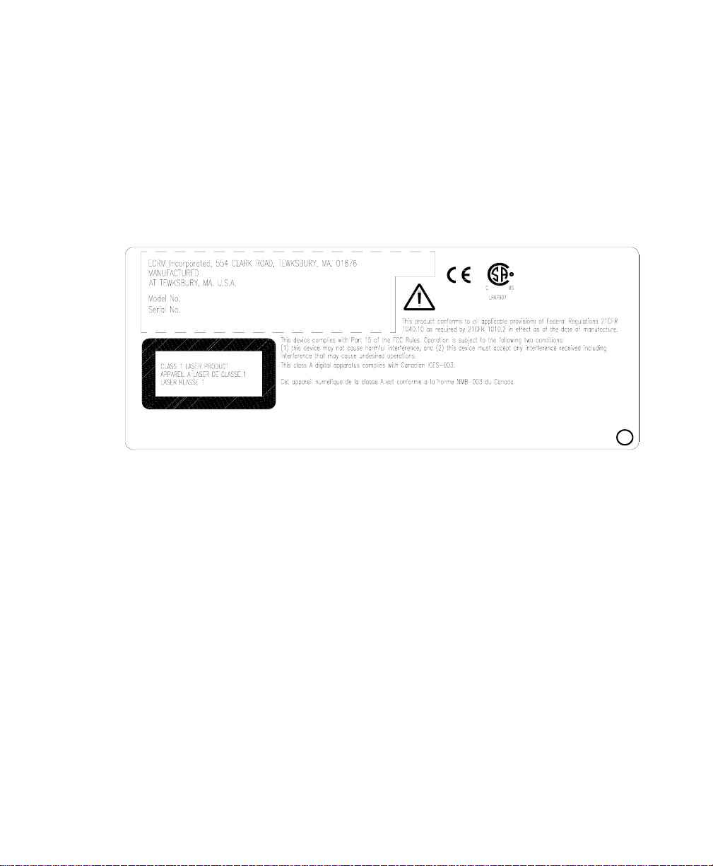
Identification and Certification Label (ratings plate)
The identification and certification label is attached to the back of
the unit, above the pinch rollers.
Figure 1-2 Identification and Certification Label

2
AG114123 Rev. 2 5
System
Operation
Introduction
A complete Mako 8 CTP / NEWS extra system includes a control
workstation, CtServer software, the platesetter, and a power
conditioner.
Workstation
The control workstation connects directly to the platesetter and runs
the CtServer software. Operating instructions for the workstation are
provided with the workstation.
The operator makes frequent use of the workstation. For that reason,
the workstation should be set up next to the platesetter.
CtServer Software
CtServer is used to send jobs to the platesetter. It is also used to
define the plate and pin bar requirements for jobs and communicate
that information to the platesetter, which displays the information on
the control panel LCD. The use and operation of CtServer is
documented in the CtServer User’s Guide.
Mako 8/NEWS extra Platesetter
The platesetter is the output device that images the plates.

6 AG114123 Rev. 2
Power Conditioner
The system power conditioner protects the system against power
quality problems like brownouts, surges, over-voltage, sags, voltage
imbalance, and line noise.
The platesetter, the workstation, and the workstation monitor all
must be plugged into the power conditioner.
Figure 2-1 AC Power and I/O Connections
AC MAINS
POWER
AC OUTLETS
PLATESETTER PC MONITOR
AC INLET
AC Power
AC Power
RS-232*
SCSI Monitor
(CtServer)
CONDITIONER
AC INLET
AC INLET
AC
INLET
Plate Line IF
AC Power
AC Power
MAKO 8/NEWS extra System
* Used by service personnel to run diagnostic programs.
PROCESSOR

AG114123 Rev. 2 7
Platesetter Parts
The main parts of the platesetter are shown and described below
Figure 2-2 External View of the Platesetter
Power Cord Receptacle
The power cord receptacle is located on the right side of the system,
as shown in Figure 2-2.
Note: In order for the system to work properly, the platesetter,
the CtServer computer, and the computer monitor must all
be plugged into the system power conditioner. Be advised
that if the devices are not plugged into the power condi-
tioner, damage resulting from voltage spikes, brownouts,
etc., will NOT be covered by the warranty.
PEDESTAL
INPUT TRAY
MEDIA
TRANSPORT
CONTROL PANEL
PIN BAR
FAN FILTER
10
POWER SWITCH
POWER CORD
RECEPTICAL

8 AG114123 Rev. 2
Power Switch
The power switch controls ac power to the system. To start up the
system, turn on the power switch located on the rear right side of the
machine. Depress zero (0) to turn OFF, depress one (1) to turn ON.
See Figure 2-2.
Note: It is recommended that the system be powered on for a 1-
hour warm-up period prior to imaging.
Pin Bar
The pin bar is used for plate registration. There are two types of pin
bars: press notch registered and edge registered.
Up to two pin bars come with the system as standard equipment.
Additional pin bars can be ordered as an option. Exposing sets of
plates with different registration notch requirements is easily
accomplished by changing the pin bar.
Control Panel
The control panel allows you to interact with the platesetter.
Commands and menu selections are controlled through this device.
Input Tray
The input tray is used to position the plate for exposing. The plate is
placed on the input tray and gently pushed against the registration
pins.
A new plate cannot be loaded until the previous plate has been
completed.
Media Transport
The media transport provides for automated delivery of media to a
customer-supplied online processor.

AG114123 Rev. 2 9
Pedestal
The pedestal is a specially designed base for the platesetter.
Fan Filters
The platesetter has several fan filters. For details about the filters,
see Chapter 4.
Starting Up the System
Turn on the power switch located on the rear right side of the
machine. Depress one (1) to turn the power ON. When the system
completes its initialization, a message appears on the display
indicating ONLINE. When ONLINE appears, the host computer
can be powered on. Once the host computer is powered on and
running CtServer or the RIP, and the Mako CTP is ONLINE,the
system is ready to expose images.
Shutting Down the System
To shut down the system, turn off the power switch located on the
lower right side of the machine. Depress zero (0) to turn the power
OFF. Shut down the system only when the display reads ONLINE,
and the second line is blank. (No operational message visible).
Once the machine is turned off, the host computer will have to be
rebooted after the machine is turned back on in order to establish
communication.
10 AG114123 Rev. 2
Using the Platesetter Control Panel
The first time you use your new system, you should review and set
all the menu parameters. Advance through the menu items and
verify or change them as needed. When you finish, the system is
ready for use.
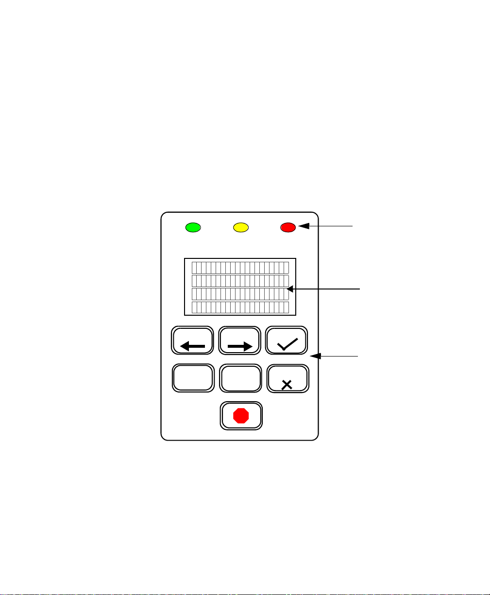
Using the Control Panel to Access Menus
The system control panel is used to access the menus. The main
parts of the control panel are shown and described below.
Figure 2-3 Control Panel
PREV NEXT
MENU SELECT
LCD
OK
CANCEL
KEYPAD
EXPOSE ERRORATTENTION
LEDS

AG114123 Rev. 2 11
Keys
Moves you backward within the menu or moves the
cursor backward within the current menu item.
Enter or exit the menu sub-system by pressing MENU
from the ONLINE or the OFFLINE state.
Moves you forward within the menu or moves the cursor
forward within the current menu item.
Increments the numeric digit under which the cursor is
positioned or scrolls through the options available for the
current menu item.
Start exposing the loaded plate. Also, from anywhere in a
numeric field, causes the next menu item to be displayed.
In the last item of a menu, causes a return to the first item
of the menu.
Cancels a pending “load plate” request, but does not stop a
job that is in progress.
The Emergency stop button. This button will stop all
moving parts of the platesetter.
LEDs
Green LED that indicates the plate is being exposed when
it is flashing. Additionally, indicates registration pin
contact when loading a plate.
Yellow LED that indicates there is a condition that
requires operator attention. The LCD display indicates
what needs to be done.
Red LED that indicates a platesetter error condition. The
LCD display indicates what the error is.
PREV
MENU
NEXT
SELECT
OK
CANCEL
EXPOSE
ATTENTION
ERROR

12 AG114123 Rev. 2
Menu Selection
There are three operator menus:
• User Preference Menu (See page 13).
• User Maintenance Menu (See page 17.)
• Test Pattern Menu (See page 19.)
To select and set parameters in any menu:
Step 1. Press MENU to enter the user menu system.
Step 2. Press SELECT until the menu you want displays on the LCD.
Step 3. Press NEXT to enter the menu.
Step 4. Set the parameter to what you want. Press SELECT to change the
value.
Step 5. Press Next to go to the next parameter until you have completed
your selections.
Step 6. Repeat steps 4 and 5 until all changes are made.
Step 7. Press MENU to exit the user menu system.
Figure 2-4 The User Menus
Preferences Test
Patterns
SELECT
NEXT
User
Preferences
User
Maintenance
Test
Patterns
Test
Patterns
SELECT SELECT
ONLINE
MENU
User Menus
NEXT NEXT

AG114123 Rev. 2 13
User Preferences Menu
UNITS OF MEASURE
OPTIONS ENGLISH (inches) or METRIC (millimeters)
The selected units of measure apply to all numeric measurement
values in various menus.
AUDIO ALERTS
OPTIONS ENABLED or DISABLED
This menu item allows you to disable or to enable the audible
alarms for the following conditions:
Error conditions, Power-up, Image complete
HORIZONTAL MAGNIFICATION
LIMITS 85.00% to 110.00%
Sets the size of the image in the horizontal direction from 85% to
110% of nominal.
VERTICAL MAGNIFICATION
LIMITS 85.00% to 110.00%
Sets the size of the image in the vertical direction from 85% to
110% of nominal.
IMAGE OFFSET
LIMITS -0.300” to +0.300” (-7.62mm to +7.62mm)
The image may be shifted to the left with a negative (-) value, or to
the right with a positive (+) value by up to 0.300 inches. Press
PREV to access the (+) and (-) sign.

14 AG114123 Rev. 2
Figure 2-5 User Preferences Menu Map
Preferences Test
Patterns
Units of
Audio Alerts
User Preferences
SELECT
Measure
Horizontal
Vertical
Image
Magnification
Magnification
Offset
PREV NEXT
MENU SELECT
OK
CANCEL
EXPOSE ERRORATTENTION
Ignore Laser
Temp. Errors
Ignore The
Processor
Processor
Speed
NEXT
Overlap
Outputting &
Imaging
User
Preferences
User
Maintenance
Test
Patterns
Test
Patterns
SELECT SELECT
MENU
NEXT
NEXT
NEXT
NEXT
NEXT
NEXT
NEXT
NEXT
User Menus
MENU
Only 1 Pin Bar
in Use
NEXT
Automatically Begin
NEXT
Imaging After
Pinching
These options are disabled when the
Output Device option is set for Tray.
ONLINE
ONLINE
Use the
NEXT
Plate Line Interface
Use the Transport
as an Output Tray
NEXT
NEXT
Registration Delay
Before Pinching
Plate
This manual suits for next models
1
Table of contents


