Scotchman PRESSPRO 176MT User manual

www.scotchman.com
PRESSPRO
MODEL 176MT
SCOTCHMAN IND. - 180 E US HWY 14 - PO BOX 850 - PHILIP, SD 57567 Phone: 1-800-843-8844
VERSION 2 - January 2022
MOVABLE TABLE

PAGE 2
SCOTCHMAN INDS. - 180 E US HWY 14 - PO BOX 850 - PHILIP, SD 57567 Phone: 1-800-843-8844
1 General information and specifications ...................................................................5
1.1 Technical data ......................................................................................................5
2 Safety advice ..........................................................................................................6
2.1 Users responsibility...............................................................................................6
2.2 Basic safety advice ..............................................................................................6
2.3 Out of use ............................................................................................................7
3 Installation ...............................................................................................................8
3.1 Deliver condition ..................................................................................................8
3.2 Transport ..............................................................................................................8
3.3 Environmental conditions .....................................................................................8
3.4 Bolting the machine to the floor............................................................................8
3.5 Installation of the hydraulic unit ............................................................................9
3.5.1 Connecting hydraulic hoses ..............................................................................9
3.6 Oil tank filling .......................................................................................................10
3.7 Electrical connection .............................................................................................11
4 Functions of the press .............................................................................................11
4.1 Hydraulic unit .......................................................................................................12
4.1.1 On / Off switch ..................................................................................................12
4.1.2 Emergency button ............................................................................................12
4.1.3 Direction control valve ......................................................................................12
4.1.4 Pressure gauge ................................................................................................13
4.1.5 Pressure regulation valve .................................................................................13
4.1.6 Speed setting valve...........................................................................................13
4.1.7 Hand pump .......................................................................................................13
5 Getting started ........................................................................................................14
5.1 De-aerating the press ..........................................................................................14
5.2 De-aerating the hand pump .................................................................................14
5.3 Positioning of cylinder ..........................................................................................14
Introduction
TABLE OF CONTENTS

PAGE 3
SCOTCHMAN IND. - 180 E US HWY 14 - PO BOX 850 - PHILIP, SD 57567 Phone: 1-800-843-8844
5.4 Regular use .........................................................................................................15
5.5 Working period ....................................................................................................16
5.6 Adjusting press cylinder/table position ................................................................16
6 Servicing and maintenance ....................................................................................17
6.1 Oil tank draining....................................................................................................17
6.2 Contact your supplier ...........................................................................................17
7 Appendixes .............................................................................................................18
7.1 Appendix I: Electric scheme for a press with a manual operated hydraulic unit ...........18
7.2 Appendix II: Hydraulic schemes ..........................................................................19
7.3 Appendix III: Spare parts .....................................................................................21
Fig. 1 Technical specifications PressPro Model 176 MT ..........................................5
Fig. 2 Bolting the machine to the floor........................................................................8
Fig. 3 Installation of the hydraulic unit .......................................................................9
Fig. 4 Securing Hydraulic Unit ...................................................................................9
Fig. 5 Hydraulic Hoses & attachment locations..........................................................9
Fig. 6 Fixing hose clamps ..........................................................................................10
Fig. 7 Overview of controls ........................................................................................11
Fig. 8 On / Off switch .................................................................................................12
Fig. 9 Emergency switch ...........................................................................................12
Fig.10 Directional control valve .................................................................................12
Fig. 11 Pressure regulation .......................................................................................13
Fig. 12 Speed setting valve .......................................................................................13
Fig. 13 Hand pump ....................................................................................................13
Fig. 14 Moving the cylinder ........................................................................................15
Fig. 15 Adjusting press/cylinder position.....................................................................16
Fig. 16 Examples of type labels...................................................................................17

PAGE 4
INTRODUCTION
This manual helps you to install, operate and maintain your press. Always read this manual
before you start working with the machine. If you have any questions, please contact your
supplier. The manual gives safety instructions where necessary to assure a safe use of the
machine. These safety instructions are clearly marked with the following symbol:
Always follow the instructions mentioned with this symbol to prevent damages to the machine
or injury to the operator. In case of doubt, please contact your local supplier.
The supplier of the press can not be held responsible for any
damages or injuries when the machine is modified by a third
party or when maintenance is done by unqualified persons.
If you want to contact your local supplier about your press, always mention its serial number
on the machine label. This label is located on the right side of the head of the press. When
you have questions about the hydraulic unit, also mention this serial number. The label is
located on the back of the hydraulic tank.
PAGE 5
SCOTCHMAN IND. - 180 E US HWY 14 - PO BOX 850 - PHILIP, SD 57567 Phone: 1-800-843-8844
1. General information and specifications
This hydraulic portal press is designed for:
bending and straightening of large sheets, beams, profiles, pivots, shafts etc.
(dis)assembly of bearings, bushings or pivots
stamping, punching, forming of a wide range of materials
This machine can be used in repair shops, work shops, etc. To enable more options, the machine can
be equipped with a flat lower table for example.
1.1 Technical data
Fig. 1 Technical specifications Scotchman PressPro Model 176 MT
The given parameters of the piston movements are maximum values and can be up to 25% lower.
Parameters are valid with minimum oil temperature of 86°F (30°C).
Pressure force
Maximum pressure
Cylinder stroke
Oil delivery
Total oil capacity
(tank and cylinder capacity)
Oil type (See Pg. 13)
Press speed
Approach speed
Return speed
Motor
Voltage
Frequency
Revolutions per minute
Insulation protection
Insulation classification
Weight
Diameter cylinder
Diameter piston rod
Diameter piston head
kW/hp
V
Hz
rpm
IP
-
pounds
in.
in.
in.
I
4hp
176
176
3698.5
15-3/4
1.875/
27.6
15
HL46
.094
.29
.37
50/60
3000
54
5000
11.02
4.92
6.3
USA STANDARD
US tons
psi
in.
gal/min
in/sec
in/sec
in/sec
(delivered with an extra cylinder extension to reach the table)
Vertical light
Table size ( L x W) in.
in.
Table height / Working height
Working Width in.
in.
68.5 x 39.25
27-1/2
43 5/16
29-15/16
220 or 440
Three Phase
TONS
gallons
Pressure force
Maximum pressure
Cylinder stroke
Oil delivery
Total oil capacity
(tank and cylinder capacity)
Oil type
Press speed
Approach speed
Return speed
Motor
Voltage
Frequency
Revolutions per minute
Insulation protection
Insulation classification
Weight
Diameter cylinder
Diameter piston rod
Diameter piston head
kN
bar
mm
ltr/min
liter
-
mm/sec
mm/sec
mm/sec
kW
V
Hz
rpm
IP
-
kg
mm
mm
mm
220 or 440
I
3
160
1570
255
400
7.1/
27.6
57
HL46
54
2265
280
125
160
TONS M E T R I C
Three Phase
50/60
3000
7.48
9.35
2.40
(delivered with an extra cylinder extension to reach the table)
Table height / Working height
Working Width
Vertical light
Table size ( L x W) mm 1740 x 996
mm 700
mm 1100
mm 760
Warning: proper use of the machine is necessary at all times, to prevent
damages to the machine and injury of the operator. Therefore operation
of the press is only allowed by persons who have read, understood and
follow this manual.
PAGE 6
2. Safety advice
2.1 Users responsibility
Safe use of the hydraulic press can be achieved in daily work when all the necessary
precautions are taken. It is the responsibility of the user to ensure that:
· the machine is used as directed;
· the machine is used in perfect working condition and the safety installations are checked
regularly;
· none of the safety and warning instructions are removed from the machine and these
remain legible;
· all regular maintenance operations are conducted as prescribed;
· only original spare parts are used;
· the direction valve seal is not removed.
2.2 Basic safety advice
Before starting work, inspect the machine carefully. Replace all worn or defective parts immediately.
Keep all parts in good condition and secured in place. Tighten nuts, bolts and screws to keep the
equipment in good working condition.
Note: the supplier of the press can not be held responsible for any
damages or injuries when the machine is modified or when maintenance
is done by unqualified personnel.
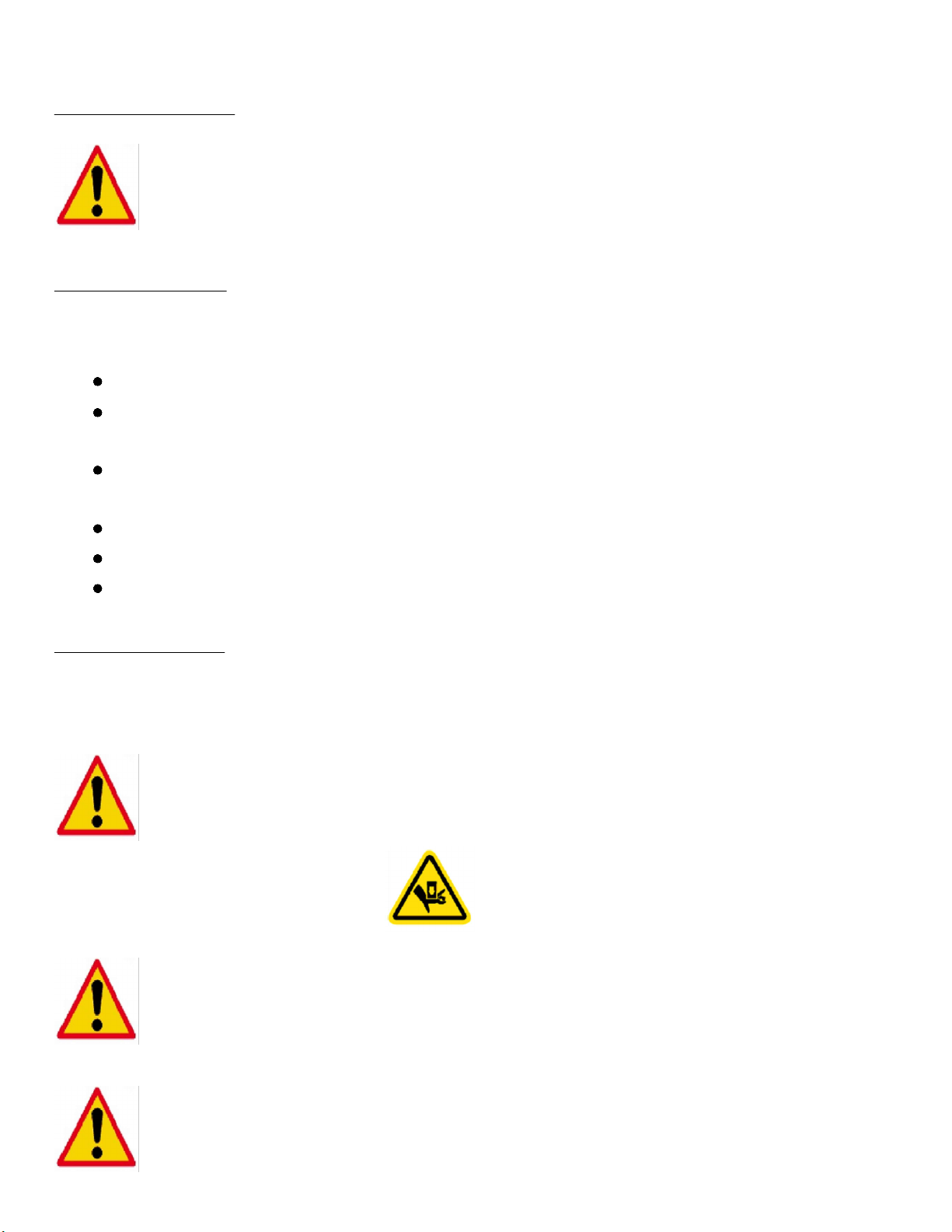
Warning: do not put your hands into the working area when the piston is
moving. Hands or any other part of the body in this danger zone can get
smashed by the piston. The danger zone is clearly marked on the left and
right side with the following symbol:
Warning: never turn off the machine when pressing force is being applied to
the work piece. Unexpected force expansion when restarting, can damage
the machine or injure the operator. Therefore always release the force from
the object, move the piston upwards and then safely turn off the press.
Warning: always wear safety shoes, safety glasses, ear protection and
body fitting clothes to prevent injuries to any part of the body.
PAGE 7
Note: do not use the machine in the following conditions:
· explosion hazard zones;
· outdoors;
· extreme temperatures +5°C < > +50°C
Note: maximum pressing force can be exerted for a short time only.
Caution: any welding operations on the press table are prohibited. This can
damage the machine or the operator can get dangerously injured.
2.3 Out of use
Do not use the machine when:
· The operator has not read or not understood the manual.
· Maintenance has not been done by qualified personnel.
· The press is not complete or non-original spare parts have been used.
· Any worn parts are visible.
· The specifications of the power supply are not conform the information stated at the motor plate +/-10%.
· The power supply plug is not equipped with a protection circuit.
· Unprotected bystanders are present.
Note: the machine MUST be bolted to the floor - see Chapter 3 Installation .
Never use a machine unless it's bolted to the floor. It can tip over if heavy
parts are loaded on the table. This can cause severe injury or death!! Use
the press in the vertical position ONLY .
www.scotchman.com

PAGE 8
SCOTCHMAN IND. - 180 E US HWY 14 - PO BOX 850 - PHILIP, SD 57567 Phone: 1-800-843-8844
3. Installation
3.1 Deliver condition
The press is delivered in the following condition:
· Hydraulic unit not installed to the frame. It is delivered packed on the table or separately.
· Cylinder fixed in the middle of the press.
· Hydraulic unit without oil.
3.2 Transport
3.3 Environmental conditions
The machine should be placed in:
· A clean- dry- and dust free room.
· A surrounding temperature of +5°C < > +50°C.
· A maximum humidity of 90%, not condensing.
· An area with enough working light.
· An area with a flat, hard floor, where good fixing of the press is possible.
3.4 Bolting the machine to the floor
Note: When press is delivered, check for freight damage before
signing anything. If you later find anything damaged while unpacking
or setting up the press STOP and contact Scotchman Ind.
In all cases of transporting the press, take care of the following precautions:
Mount the hydraulic unit on the inside of the frame on the table - Not on the outside!
Fix the cylinder in the middle of the press.
Fasten the frame properly to avoid abrupt movements.
PRESS IS TOP HEAVY!!
BOLT PRESS TO THE FLOOR!!
When the machine is positioned in the desired
location, it should be bolted to a concrete floor as
shown with (4) 10 mm (3/8") screws and plugs
(not included). The press is made with a hole in
each of the (4) table-legs for this purpose .
Fig. 2 Bolting Scotchman PressPro Model 176 MT to the floor.

PAGE 9
3.5 Installation of the hydraulic unit
Hyd. Power
Unit is
shipped as
shown.
It must be
bolted to the
angle iron
mounts &
the hoses
need to be
connected to
the press.
Remove the back
bolt & loosen the bolt
on the angle iron.
Rotate the angle iron
to horizontal and
install the back bolt.
Tighten both bolts.
This must be done
on both sides.
Fig. 3 Hydraulic Unit and mounting brackets as shipped from the factory
3.5.1 Connecting hydraulic hoses
Fig. 5 Hydraulic hoses and attachment locations
Once the hydraulic unit is mounted, the hoses must be attached. The caps in
the hose and fitting are color coded. In the example shown below:
Yellow hose to Yellow fitting & Red hose to Red fitting
Tip: the hydraulic unit weighs about 110 lbs!!
When placing the unit in the correct position, make
sure to use enough man or machine power to lift
the unit.
Hydraulic Unit is bolted to the brackets with (4) M10 bolts on the bottom.
Also See Fig. 6 on the next page for overall view.
(4) M10 bolts
secure Hyd. Unit
Hyd. Unit in place
Fig. 4 Securing
Hydraulic Unit

PAGE 10
3.6 Oil tank filling
The press is delivered without oil. Before starting up, the tank needs to be filled.
Mobile DTE 10 Excel 46 or Mobile DTE 25 or similar hydraulic oil is recommended.
Bring the piston into its upper position.
Remove the filler plug on top of the hydraulic unit.
Replace the filler plug.
Start the hydraulic unit.
De-aerate the press: Lower the piston (with the direction control valve / joystick) 4 in. and
bring the piston back to its upper position. Then lower the piston 8 in. and bring it back
to the upper position. Then lower the piston 12 in. and then back to the upper position.
Then move the piston down again to 15 to 15-3/4 in. and bring it back up to the upper
position.
Turn off the hydraulic unit.
Remove the filler plug again and check oil level.
If needed, add more hydraulic oil to the tank.
Replace the filler plug.
To properly fill the oil tank:
On top of the cylinder there are (2) threaded holes. The centered hole is for the large
diameter (18mm) hose from the reservoir. The other hole is for the small diameter
(5mm) pressure gauge hose.
Top of cylinder
Fig. 6 Keep hoses straight - no sharp bends
MAKE SURE ALL HOSES ARE TIGHTENED SECURELY AND CONNECTED IN THE
CORRECT LOCATION BEFORE FILLING RESERVOIR AND OPERATING THE PRESS
Make sure there are no sharp bends in the hoses between the clamps and connections
to the hydraulic unit as shown above.
Fill the tank with a sufficient amount of oil. The total capacity of this press including
the reservoir and cylinder is 15 gal. (57 liters).

PAGE 11
Note: never run the press when its low on oil. This will damage the hydraulic
unit and cause the press to malfunction.
The machine must be connected to 220V 3ph or 440V 3ph power.
The electric circuit must be protected by a fuse or circuit breaker with an adequate rating.
The motor direction can be changed by swapping (2) of the incoming phases (SEE BELOW).
NOTE: check if the turning direction of the motor is in the direction of the arrow,
looking at the motor from above. THE WRONG DIRECTION CAN DAMAGE THE
MACHINE IN A VERY SHORT TIME!!
3.7 Electrical connection
PAGE 11
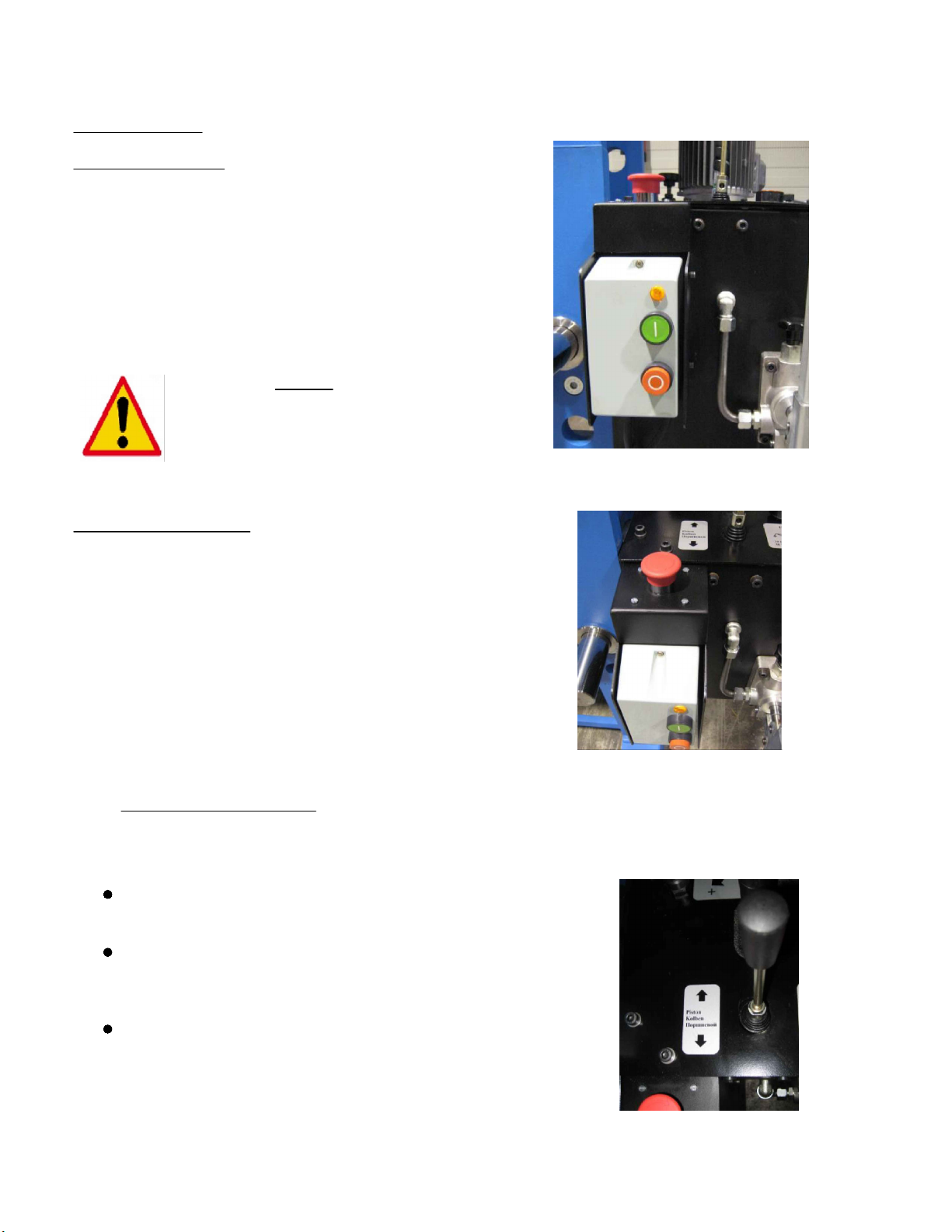
4. Functions of the press
Fig. 7 Overview of controls
4.1.1
On / Off
Switch
4.1.2
Emergency
Button
4.1.5
Pressure
Regulation
Valve
Oil Filler
Plug
4.1.3
Direction Control
Valve / Joystick
4.1.6
Speed Setting
Valve
4.1.7
Hand Pump
PAGE 12
4.1 Hydraulic unit
4.1.1 On / Off switch
The on / off switch is situated at the front of the hydraulic tank.
· Pushing the green button will start the motor of the
hydraulic unit.
· Pushing the red button will stop the motor of the hydraulic
unit immediately. All parts will stay in the position where
they are at that moment
Fig. 8 On / Off switch
4.1.3 Direction control valve
The direction control valve / joystick is located in the top cover of the hydraulic unit.
The valve has 3 lever positions:
Fig. 10 Directional control valve
Middle position: if the lever has not been operated, the valve
will always return to this position. There is no movement of the
press ram.
Upper position: if the lever is positioned upwards, the press ram
of the cylinder will move upwards. As long as the valve is
operated, the press ram will move. When the lever is released,
the press ram will stop and stay in this position.
Lower position: if the lever is positioned downwards, the press
ram of the cylinder will move downwards. As long as the valve
is operated, the press ram will move. When the lever is
released, the press ram will stop and stay in this position. If
the press ram reaches its lowest position (end of the cylinder
stroke) the pressure of the cylinder will automatically drop to
almost zero, to prevent damages to the press ram head.
4.1.2 Emergency button
The emergency button is located on top of the on / off switch.
Pushing the red emergency button in case of emergency will
stop the electric motor of the hydraulic unit immediately. All other
parts will stay in the same position they are at that moment.
To restart the hydraulic unit again:
· Make sure that the dangerous situation is solved.
· Reset the red emergency button by turning it counter
clockwise, the button will pop-up again.
· Push the green button from the on / off switch again.
Fig. 9 Emergency switch
WARNING: NEVER turn off the machine
when pressing force is being applied to the
work piece. Unexpected force expansion
when restarting, can damage the machine
or injure the operator.
PAGE 13
4.1.4 Pressure gauge
4.1.6 Speed setting valve
The speed setting valve is located in the top
cover of the hydraulic unit.
If the lever is in the lower position, the piston
will move with low speed when the directional
control valve is activated. If the lever is in the
upper position, the piston will move with high
speed when the direction control valve is
activated. When the piston is reaching the
work piece with high speed, it will
automatically switch to low speed as soon as
it feels counter pressure. This has no
influence on the maximum working pressure
or working force. Fig. 12 Speed setting valve
The pressure gauge is located in the head (in front toward the top) of the press. The gauge shows
the pressure in psi & bars. For this press the maximum pressure is as follows:
If this maximum pressure is reached, the maximum capacity of the press is reached as well.
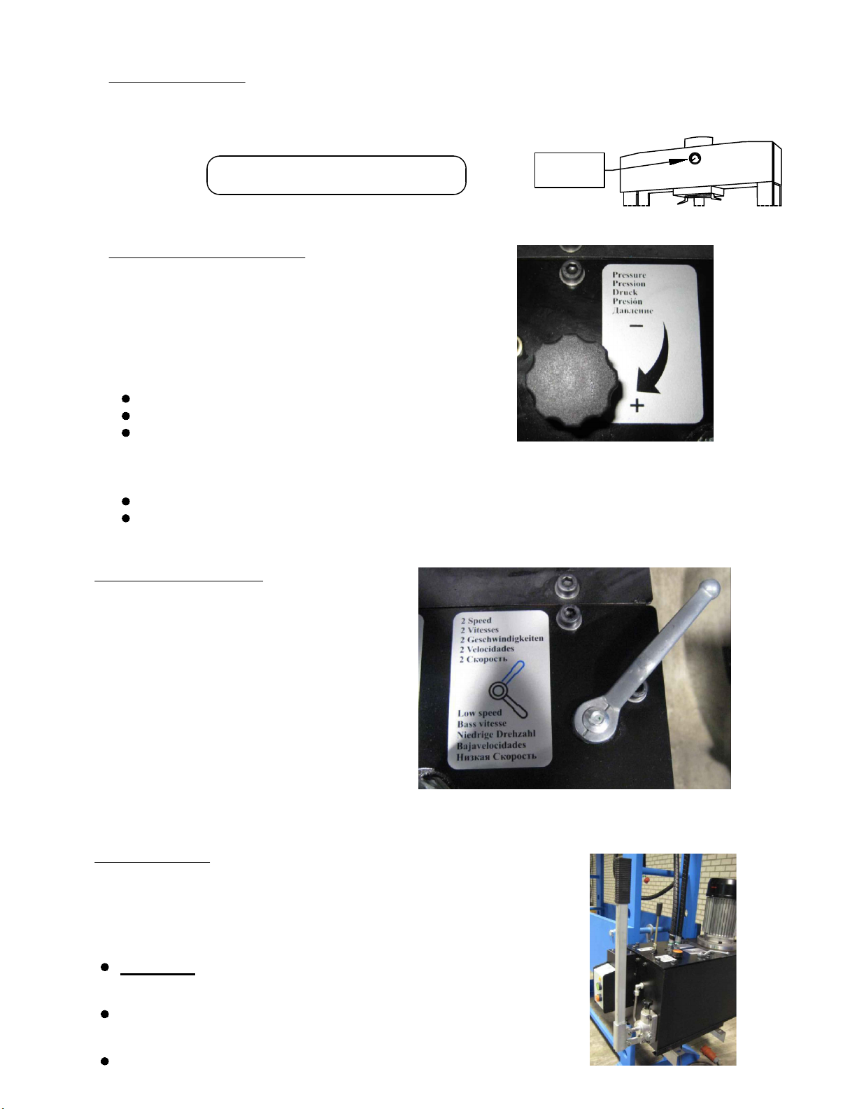
4.1.5 Pressure regulation valve
Fig. 11 Pressure regulation
Adjusting the pressure:
Start the hydraulic unit.
Raise the press ram so no force is applied.
Turn the knob on the pressure control valve
counter clockwise to lower the pressure.
Do not remove the knob!!
Note that it can be turned far enough to unscrew from the pressure control valve.
Lower the press ram to the work piece and keep force applied with the joystick.
Slowly turn the knob on the pressure control valve clockwise & carefully raise the
pressure while watching the pressure gauge.
The pressure regulation valve is located in the top cover of the
hydraulic unit. With this valve the maximum pressure, referring
to the maximum press capacity, can be changed. Turning the
knob clockwise will increase the pressure, turning the knob
counter clockwise will reduce the pressure.
4.1.7 Hand pump
The press is equipped with a hand pump, located on the front panel of
the hydraulic unit. This pump can be used for manual pressing
functions or when accurate force setting is necessary.
To use the hand pump:
Fig. 13 Hand pump
TURN OFF the hydraulic unit by pushing the red button of the
on/ off switch.
Set the directional control valve in the required position
(up- or downwards).
Start pumping the hand pump with its lever.
PRESSURE
GAUGE
PressPro 176MT: 3700psi (255 bar)

PAGE 14
5. Getting started
5.1 De-aerating the press
5.2 De-aerating the hand pump
5.3 Positioning of cylinder
To start the press for the first time, make sure:
The press is installed correctly (see former paragraphs).
The oil tank is filled with a sufficient amount of oil.
The hydraulic hoses are tightened correctly to the cylinder and to the hydraulic unit.
The machine is connected to the correct voltage & grounded per local code.
When starting up for the first time or when the hydraulic hoses have been disconnected from the
hydraulic unit or cylinder, the system need to be de-aerated. To do this:
Start with the piston in the upper position (as delivered condition).
Make sure there is no work piece on the table.
Start the hydraulic unit.
Move the piston to the down position by activating the directional control valve.
Move the piston back to the up position by activating the direction control valve.
Repeat this complete cycle at least 6 times to ensure that all the air is out of the system.
Note: incorrect de-aerating can cause unexpected movements of the piston and
cause the press to malfunction.
When starting up for the first time or when maintenance of the hydraulic unit is performed, the hand
pump needs to be de-aerated. To do this:
Start with the piston in the upper position.
Make sure there is no work piece on the table.
Turn off the hydraulic unit by pushing the red button at the on / off switch.
Set the directional control valve in the downwards position.
Start pumping the hand pump with its lever until the piston reaches the lower position.
Set the directional control valve in the upwards position.
Start pumping the hand pump with its lever until the piston reaches the upper position.
Repeat this complete cycle at least 3 times to be sure all air is out of the hand pump.
Note: incorrect de-aerating can cause unexpected movements of the piston and
cause the press to malfunction.
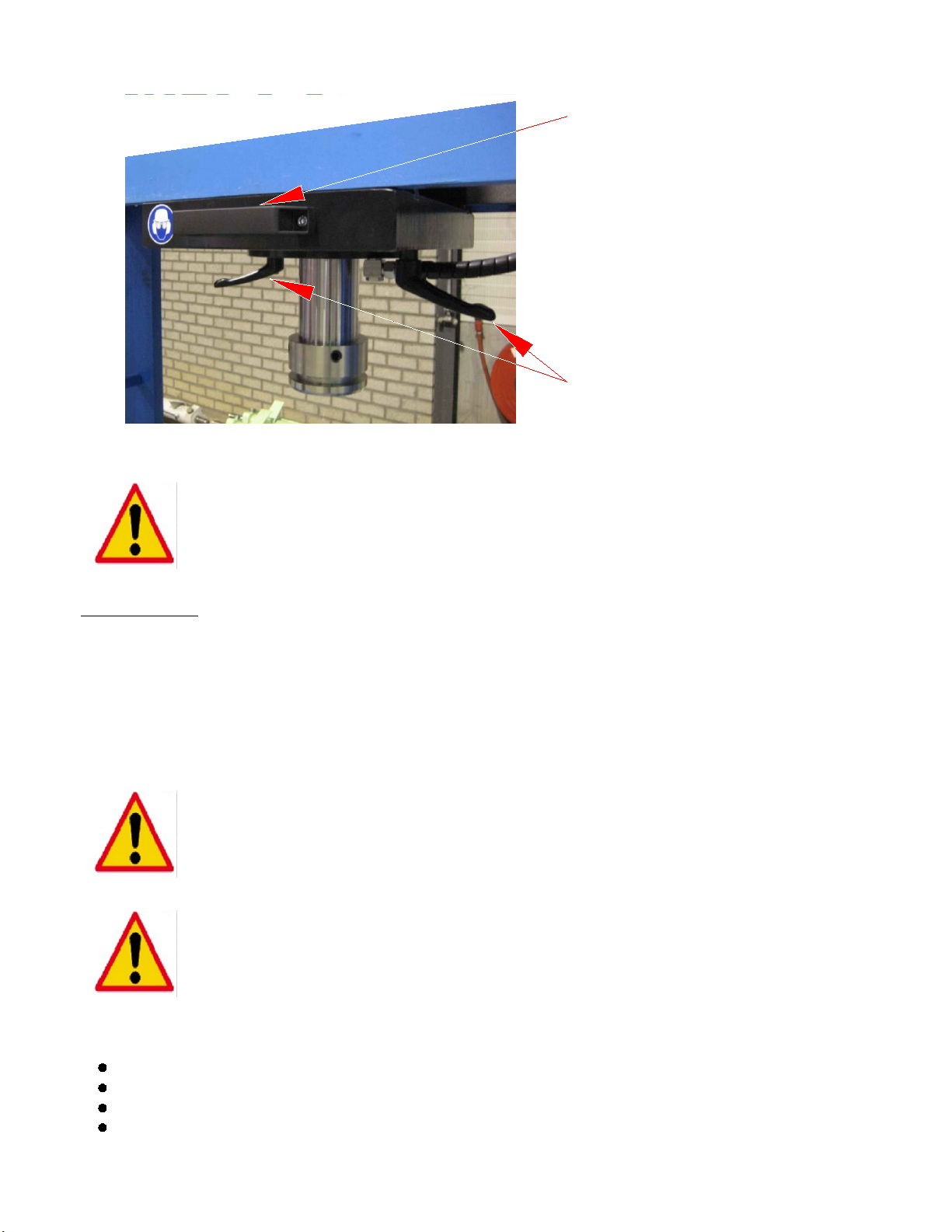
Move the complete cylinder to the left or right by means of the bow grip (handle).
Tighten the levers again when the cylinder is in the right position. Manual tightening is enough.
Do not use a wrench - Do not over-tighten the levers.
When your work with the press is finished, move the cylinder back in its center position.
Turn both levers two turns counter clockwise to loosen.
DO NOT COMPLETELY REMOVE THE LEVERS!!
All presses are equipped with a movable cylinder which makes it possible to correctly align
the press ram with the work piece. To move the cylinder side to side:
PAGE 15
bow grip
levers
Fig. 14 Moving the cylinder
5.4 Regular use
Place the work piece on the table in alignment with the piston rod. If this is not possible, reposition the
cylinder and portal to achieve the best alignment.
Take caution when performing operation on elements that are likely to fly off, break (especially casting
element and hardened elements) or bounce up as a result of the applied force. In this case, a cover
must be installed around the work piece or the operator should stand at a safe distance.
After correct placement of the work piece, pressing force can be applied as described in the previous
chapters.
When pressing operations are finished:
Return the piston back to its outer upper position.
Position the cylinder back to the centre of the machine.
Turn off the hydraulic unit.
Clean the machine and working area.
Tip: working with the cylinder in the outer left or outer right position, will
shorten the durability of the press. Working in the centre of the press is
preferable.
Warning: always wear safety shoes, safety glasses, ear protection and
body fitting clothes to prevent injuries to any part of the body.
Note: upward movement of the piston is only allowed for returning the
piston to its start position. Any other use of the return stroke (e.g.
stretching) can result in broken parts and de-function of the press.

PAGE 16
The machine is not designed for continuous operation.
Maximum cycle intensity is 2 per minute.
Maximum 10 minutes working time with maximum cycle intensity.
Note: when you do not take the maximum working period into account, it can
result in overheating the hydraulic oil and heating up the hydraulic unit. The
machine can get damaged and the operator may suffers burns.
5.5 Working period
5.6 Adjusting press cylinder/table position
Section 5.3 explains how to change the position of the cylinder from side to side. The cylinder on
the PressPro 176 MT can be moved front to back as well. This is done by anchoring the four legs
on the table (1) solidly to the floor, and then moving the press head back and forth to wherever it is
needed. When the desired position is achieved simply lock the press head into place and begin use.
In Figure 15 below, the dotted lines (2) represent the parts of the press that actually move. On both
sides, the rollers (3) ride on a ledge (4) that is welded to the table.
1.
Fig. 15 Moving the cylinder front-to-back.
2.
3.
4.
4.

PAGE 17
6. Servicing and maintenance
Note: replacing parts, electrical, mechanical or hydraulic, can only be done by
qualified personnel. Your supplier can not be held responsible for damages or
injuries as result of inappropriate servicing.
Daily
Remove dust and dirt
from the table and
around the press.
Check the press for
visible damages.
Weekly
Check oil level of the
hydraulic unit.
Check electrical
connections.
Half-yearly
Inspect all hydraulic
fittings and hoses and
tighten any loose
connections.
Inspect and tighten all
loose fixing bolts.
In case of leakages, damaged parts or bare electric cables; do not use the machine before it is
repaired.
Always use original spare parts.
Note: when starting with maintenance, always unplug the electrical connection
and make sure there is no hydraulic pressure on the system. Both can result in
injuries to the maintenance operator.
6.1 Oil tank draining
Replace the hydraulic oil at least once a year. A drain plug is located at the bottom of the oil tank. If
the inside of the tank is not clean, remove the top cover of the tank and clean the tank from the inside.
Check if the drained oil has a gray color or if there are metal particles visible in the oil. This can
indicate worn out parts in the cylinder or the hydraulic unit.
You have to prevent spilling dirt and water inside the oil tank.
6.2 Contact your supplier
If there are any questions, please contact your supplier.
Always mention the serial number on the machine label. This label is located at the frame of the press
(front right side). When you have questions about the hydraulic unit, also mention its serial number.
The label is located on the back of the hydraulic tank.
Yearly
Replace the hydraulic
oil of the unit. See
instruction below.
Fig. 16 Examples of type labels
SCOTCHMAN IND.
HYDRAULIC PRESS
MODEL
PRESSPRO 176MT
S/N 10061N120001
FRAME HYDRAULIC TANK

PAGE 18
7. Appendixes
7.1 Appendix I: Electric schematic for a press with a manual operated hydraulic unit
230V 460V
Brown
Black
Blue
4
3
LC1DXX
SCHNEIDER
LRDXX
SCHNEIDER
LINE POWER
START
BUTTON
Brown
Black
Blue
* Follow Instruction
Sheet In Motor Box
If Provided
Brown
TO MOTOR*
SET OVERLOAD TO
FLA SHOWN ON
SERIAL NO. PLATE
W2
U2
V2
U1
V1
W1
W2
U2
V2
U1
V1
W1
NOTE: Swap (2)
Incoming
Power Wires to
change Rotation
21
L1 L2 L3
13 21 A1
14 22
A2
97 98 95 96
T1 T2 T3
EMERGENCY
STOP
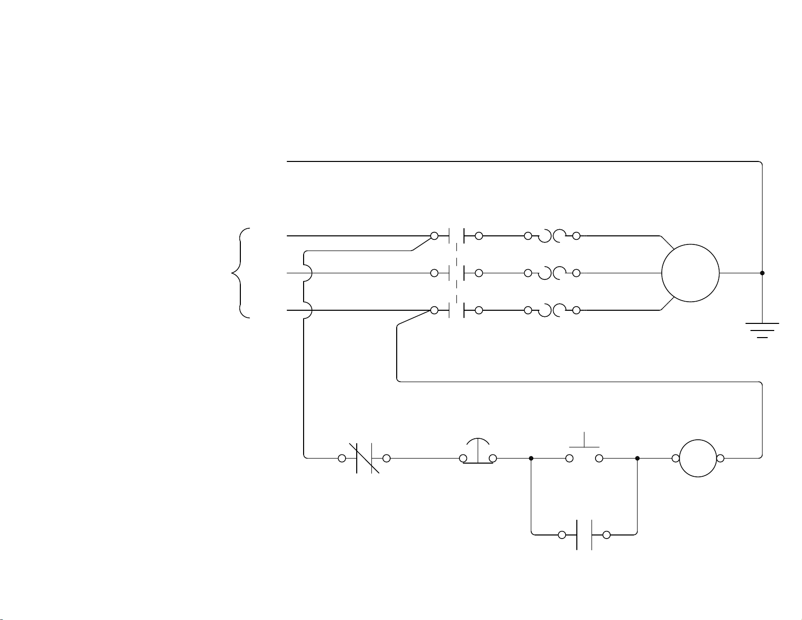
L3
L2
L1 T1
T3
MTR
1M 1OL
T2
INCOMING SUPPLY
(BY CUSTOMER)
PROVIDE MAXIMUM
UPSTREAM
PROTECTION PER N.E.C.
CODE 430-52 AND TABLE
430-152.
GND
95 96
1OL E-STOP
1 2
1PB
START
3
4
2PB
A2
1M
A1
1M
1314
L1
L3
L2
SEE MOTOR TAG
FOR DETAILS
PAGE 19

PAGE 20
Table of contents
Other Scotchman Industrial Equipment manuals

Scotchman
Scotchman PRESSPRO 66 User manual

Scotchman
Scotchman DO-150-24M User manual

Scotchman
Scotchman GAA-600-90 CNC User manual

Scotchman
Scotchman IRONWORKER 6509-24M User manual

Scotchman
Scotchman CPO-315-RFA-BL User manual

Scotchman
Scotchman GAA-500-90 CNC DT20 User manual

Scotchman
Scotchman 6509-24FF User manual


