ECS MT-131-DHU User manual

© ECS Electronics B.V. MT-131-DHU / 120515TTRevision: 0
Partnr.: MT-131-DHU
•
Fitting instructions electric wiring kit tow bar with 13-P socket up to DIN/ISO Norm
11446.
•
We would expressly point out that assembly not carried out properly by a competent
installer will resultin cancellation of any right to damage compensation, in particular
those arising by virtue of the product liability act.
•
Contents of these kits and their fitting manuals are subject to alteration without
notice, please ensure that these instructions are read and fully understood before
commencing installation.
•
Do not overload circuits; the maximum loads per connection are detailed in this
manual.
•
Attention! Before Installation, please read this manual carefully and inform
your customer to consult the vehicle owners manual to check for any vehicle
modifications required before towing.
• In the event of functional problems, troubleshooting must be
limited to about 0.5 hours, contact the installers support:
Monday - Friday
08.00am - 11.00am
12.00am - 05.00pm
GMT
www.ecs-electronicsuk.co.uk
I
N
S
T
A
L
L
E
R
S
S
U
P
P
O
R
T
F
R
E
E
C
A
L
L
Mitsubishi L200 2016-

Part list
Quick
Start
Guide
follow
original
wire
Code
3:3
airbag
© ECS Electronics B.V. Pag. 2 MT-131-DHU / 120515TT
35x
4x
X
BM
3x
X
L
T
B
G
U1
U
M1
M2
5x
PARK DISTANCE CONTROL
PARK DISTANCE CONTROL
OPTION P.D.C.
3x
Pag. 18 - 19
3x
3x
2x
2x
Fuse 15 Amp.
1x
15 Amp.
Fuse 20 Amp.
1x
20 Amp.
2x

© ECS Electronics B.V. Pag. 3 MT-131-DHU / 120515TT
2
1
!Code
3:3
Double Cab
Double Cab
G
U1
U
T
L
X
ROUTING
M
*
*
*
*
M
Club Cab

© ECS Electronics B.V. Pag. 4 MT-131-DHU / 120515TT
Double Cab
3
4
1
2

Double Cab
5
6
© ECS Electronics B.V. Pag. 5 MT-131-DHU / 120515TT
1
2
Double Cab
4x
1x
Option 1
Double Cab
Option 2
4x
1x
2
1
1
2

© ECS Electronics B.V. Pag. 6 MT-131-DHU / 120515TT
8
7
30mm
60mm
1 2Ø 40 mm
Double Cab
Club Cab
1
2
3
4
5

© ECS Electronics B.V. Pag. 7 MT-131-DHU / 120515TT
9
10
Club Cab
35mm
35mm
1 2 3Ø 40 mm
4
Double Cab
T
G
U1
U
L
X
X
L
G
T
1
2
3

*
*
© ECS Electronics B.V. Pag. 8 MT-131-DHU / 120515TT
11
12
Club Cab
Club Cab
4
T
Double Cab
2x
Wire-tie 200 mm
*
1x
Wire-tie 200 mm
*
Lh Fr
*
*
G
U1
U
L
X
X
L
G
T
1
3
2

*
*
Option 2
9x
Wire-tie 200 mm
*
FOLLOW ORIGINAL
CLIP
3x
Wire-tie 360 mm
X
7x
Wire-tie 200 mm
Option 1
*
8x
Wire-tie 200 mm
*
*
1x
Wire-tie 450 mm
FOLLOW ORIGINAL
CLIP
3x
Wire-tie 360 mm
© ECS Electronics B.V. Pag. 9 MT-131-DHU / 120515TT
13
Double Cab

© ECS Electronics B.V. Pag. 10 MT-131-DHU / 120515TT
*
*
Option 2
11x
Wire-tie 200 mm
*
FOLLOW ORIGINAL
CLIP
3x
Wire-tie 360 mm
X
7x
Wire-tie 200 mm
Option 1
*
10x
Wire-tie 200 mm
*
*
1x
Wire-tie 450 mm
FOLLOW ORIGINAL
CLIP
3x
Wire-tie 360 mm
14
Club Cab

© ECS Electronics B.V. Pag. 11 MT-131-DHU / 120515TT
B
A
INFO
X
Pag. 17
SOCKET CONNECTION

15
16
© ECS Electronics B.V. Pag. 12 MT-131-DHU / 120515TT
M1
M2
Double Cab
B
M
Option 1
1
B
2
3
M
BB
4 5 67
1x
2x
MM
8 9 10
2x
1x

© ECS Electronics B.V. Pag. 13 MT-131-DHU / 120515TT
17
18
19
Double Cab
Club Cab L
M
Double Cab
B
Option 2
M
B
Club Cab

20
© ECS Electronics B.V. Pag. 14 MT-131-DHU / 120515TT
Double Cab
Club Cab
G
U1
U
G
U1
U
21
G
U1
*
*
*
*
*
FOLLOW ORIGINAL
CLIP
*
5x
U

23
© ECS Electronics B.V. Pag. 15 MT-131-DHU / 120515TT
Double Cab
Club Cab
10mm
1
2
4
U1
U
10 mm
1
2
G
2
31
4
G
U1
*
*
*
FOLLOW ORIGINAL
CLIP
*
3x
22
U

24
26
© ECS Electronics B.V. Pag. 16 MT-131-DHU / 120515TT
1x
Wire-tie 360 mm
U1
1 2
!Code
3:3
25
Orange 20 Amp.
20 Amp.
+30
+30
Brown/White 15 Amp.
15 Amp.
!TEST ALL THE CIRCUITS WITH A TEST DEVICE WITH THE CORRECT POWER
LOAD FOR EACH FUNCTION. A TEST DEVICE WITH LED’S CANNOT BE USED FOR
THIS PURPOSE.
15 Amp.
20 Amp.

© ECS Electronics B.V. Pag. 17 MT-131-DHU / 120515TT
INFO
27
Monday - Friday
08.00am - 11.00am
12.00am - 05.00pm
GMT
www.ecs-electronicsuk.co.uk
I
N
S
T
A
L
L
E
R
S
S
U
P
P
O
R
T
F
R
E
E
C
A
L
L
REINSTALL TRIM.
INFO
SOCKET CONNECTION
1-8 STOP Reverse +-
15 amp.
30+
+-
15 amp.
15+ 10 9
21W21W 21W 42W 3x21W 42W 21W 180W/15Amp 180W/15Amp
DIN/ISO
11446
Pmax
1,00 mm22,50 mm2
Yellow
Colour Blue White Green Brown Red Black Black/
Red
Brown/
White
Red White -White
1/L 23/31 4/R 5/58-R 6/54 7/58-L 8 9 10 11 12 13
Quick
Start
Guide
follow
original
wire
Code
3:3
airbag
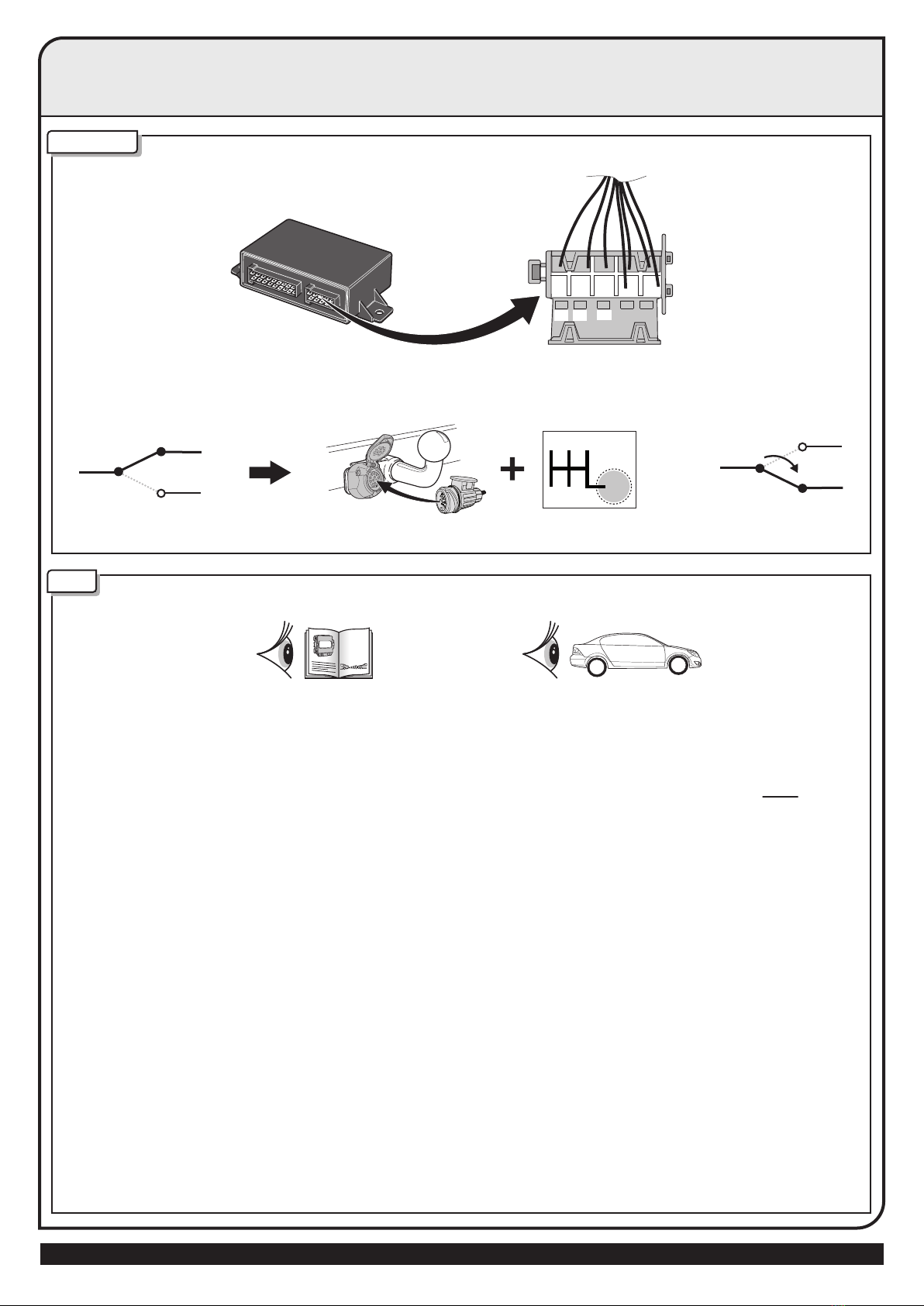
AUTO PARK-SENSOR SWITCH-OFF FUNCTION WITH THE 5D033 ECU
FOR AFTER MARKET / NON-OE PARK-SENSOR-SYSTEMS
FUNCTION
9
5
7
5
7
1 3 5
2 4 R=9
P.D.C.
PDC
Manual
531
7
9
Locate the PDC (Parking Sensor) Module in the Vehicle.
OPTION 1 When the PDC-system has no specific MUTE wire: Locate and cut the wire at ONE of
the locations A-G and connect to the ECS Towbar Wiring Kit as shown in Option 1.
Always check if cutting the wire at the selected location does not create any errors in
the PDC-system or the vehicle, if so, then select another location. In this case the cut wire
is connected and the system operates normally. When the trailer is connected. This wire
becomes disconnected by the Trailer Module. If the same module also controls the Front
Sensors then use only locations F or G to prevent the front sensors switching off.
OPTION 2 When the PDC-system has a specific MUTE wire: Check in the manual of the PDC-sysctem
which input the PDC module requires to switch off the system (+12v or Earth trigger).
Then connect the Trigger wire of the PDC system to pin 9 of the ECS connector, and
connect the required feed (+12v or Earth) to pin 7 and 5.
Be careful as connecting the wrong feed can cause damage to the PDC-system.
Always check Before and After installation the PDC System is working correctly, and where
possible any error codes.
INFO
© ECS Electronics B.V. Pag. 18 MT-131-DHU / 120515TT

OPTION 1, NO PDC MUTE
PDC UNIT
PDC MUTE
12 Volt
12 Volt
Reverse
signal
D
C
E
B
GF
A
P.D.C.
PDC
Manual
OPTIONS
A B
OPTIONS
F G
C D E
19 7
2
3
M
9
7
9
7
9
7
5
12 Volt
9 7 5
1 2
3
PDC MUTE
M
AUTO PARK-SENSOR SWITCH-OFF FUNCTION WITH THE 5D033 ECU
FOR AFTER MARKET / NON-OE PARK-SENSOR-SYSTEMS
AFTER MARKET / NON-OE PARKSENSOR-SYSTEM
P.D.C.
PDC
Manual
OPTION 2, PDC MUTE
P.D.C.
PDC
Manual
P.D.C.
PDC
Manual
PDC UNIT
© ECS Electronics B.V. Pag. 19 MT-131-DHU / 120515TT
Other ECS Automobile Accessories manuals


