JKSOGS960 /JKSOGS962 JKS Steering Brace System Installation
2 Page
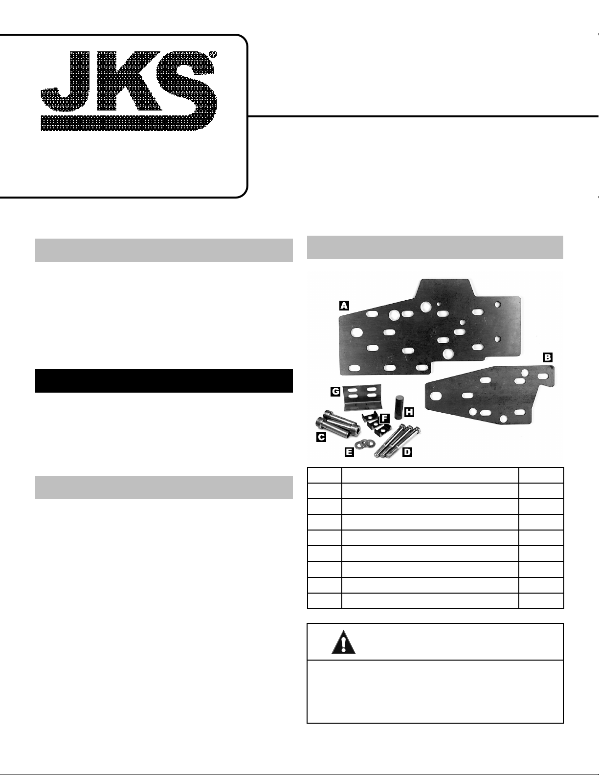
ATTENTION INSTALLER
IMPORTANT NOTE REGARDING
DUAL STEERING BRACE SYSTEM
The following instructions refer to installation of a
single Steering Brace System (PN OGS960) on the
driver-side chassis rail only. For a dual Steering Brace
System (PN OGS962), the additional parts should be
installed on the passenger-side chassis rail using the
same procedures.
NOTE: Some vehicles are factory equipped with
steering gear mounting holes on both chassis rails.
Otherwise, it will be necessary to drill new holes on
the passenger-side chassis rail to accommodate the
supplied Support Sleeves.
Installation
1. PREPARE DRIVER-SIDE CHASSIS RAIL
ZThe following items must be removed from the
chassis rail, along with any other components that
prevent the Chassis Plates (A & B) from tting
ush against mounting surface. Refer to factory
service manual for specic instructions.
ÂTow Hook & Bracket
ÂLower Radiator Support Bracket
ÂFront Swaybar
ÂFront Bumper & Bracket
ZUnbolt the steering gear and adapter plate from
the chassis. Temporarily secure the steering gear
out of the way – it should not be necessary to
disconnect uid lines or steering shaft. Discard
steering gear adapter plate.
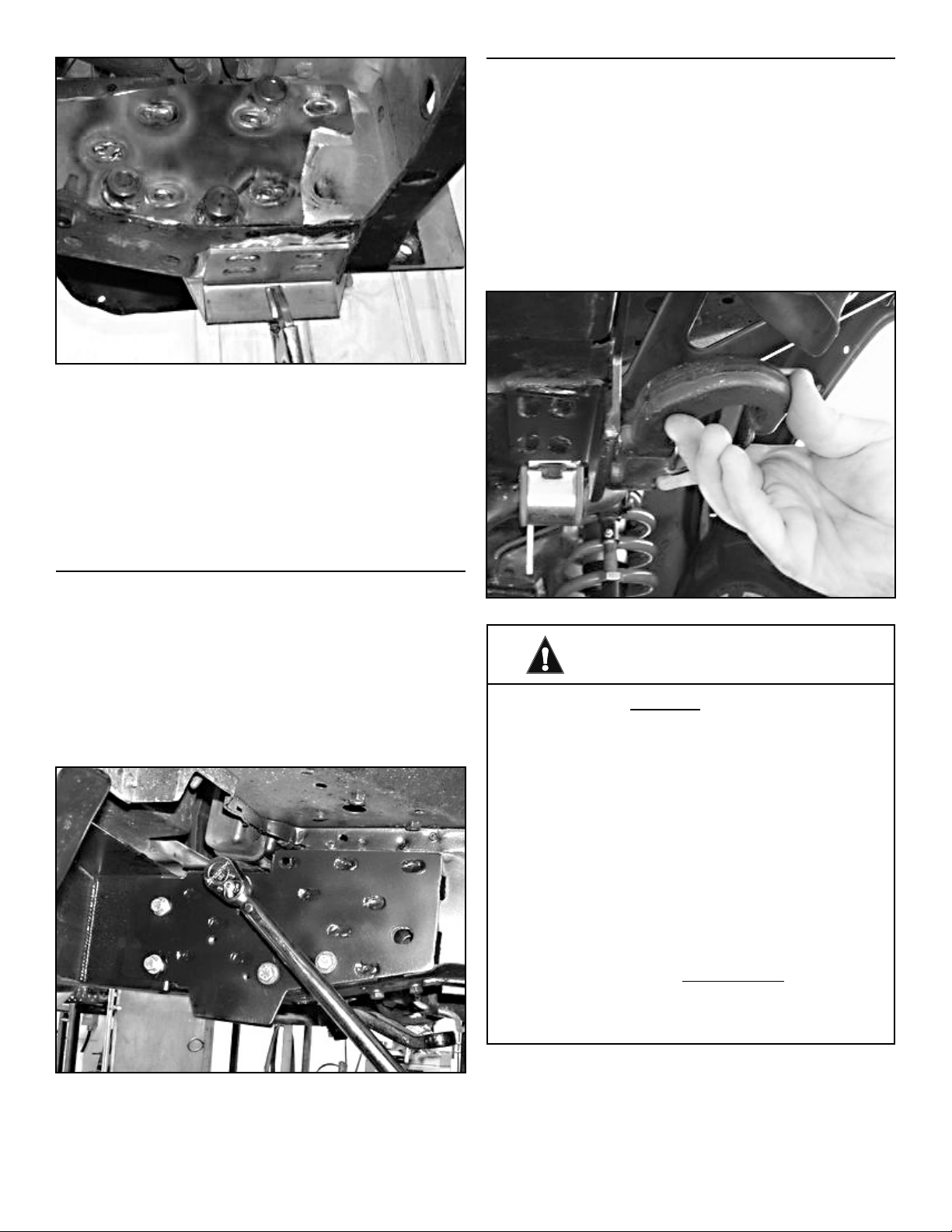
ZTest t the Inner and Outer Chassis Plates (A & B)
to the chassis rail. Mark an outline of each plate
onto chassis surface.
ZCompletely remove all paint/primer, weld slag/
spatter, or other debris from chassis surface
(inboard and outboard side) until bare metal is
exposed.
HINT: A die grinder with sanding wheel, disc
sander, or similar tool is useful for cleaning chas-
sis surface.
ZTest t the Inner and Outer Chassis Plates (A &
B) again to check for ush tment against chassis
surface, and to ensure all debris has been re-
moved from the necessary areas.
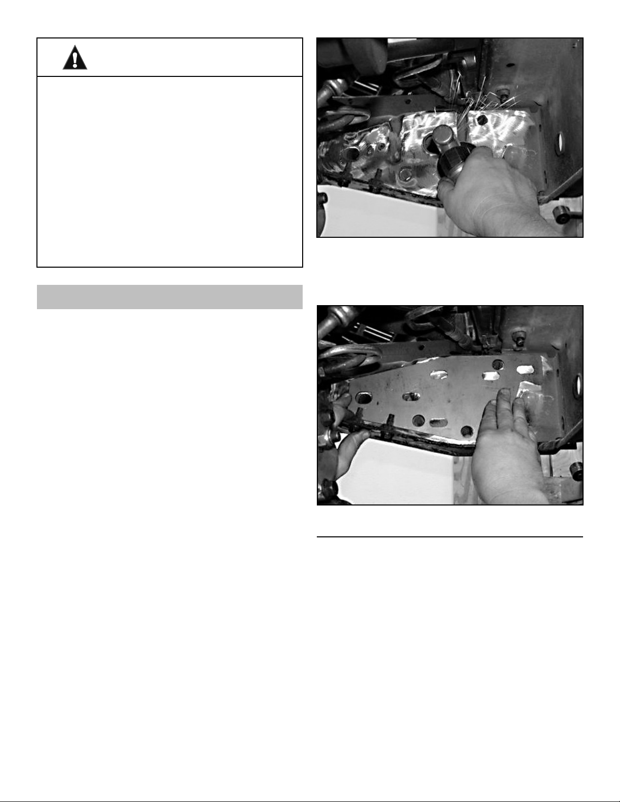
2. ENLARGE STEERING GEAR MOUNTING
HOLES IN CHASSIS
ZLocate the three (3) steering gear mounting holes
on the inboard and outboard side of chassis rail.
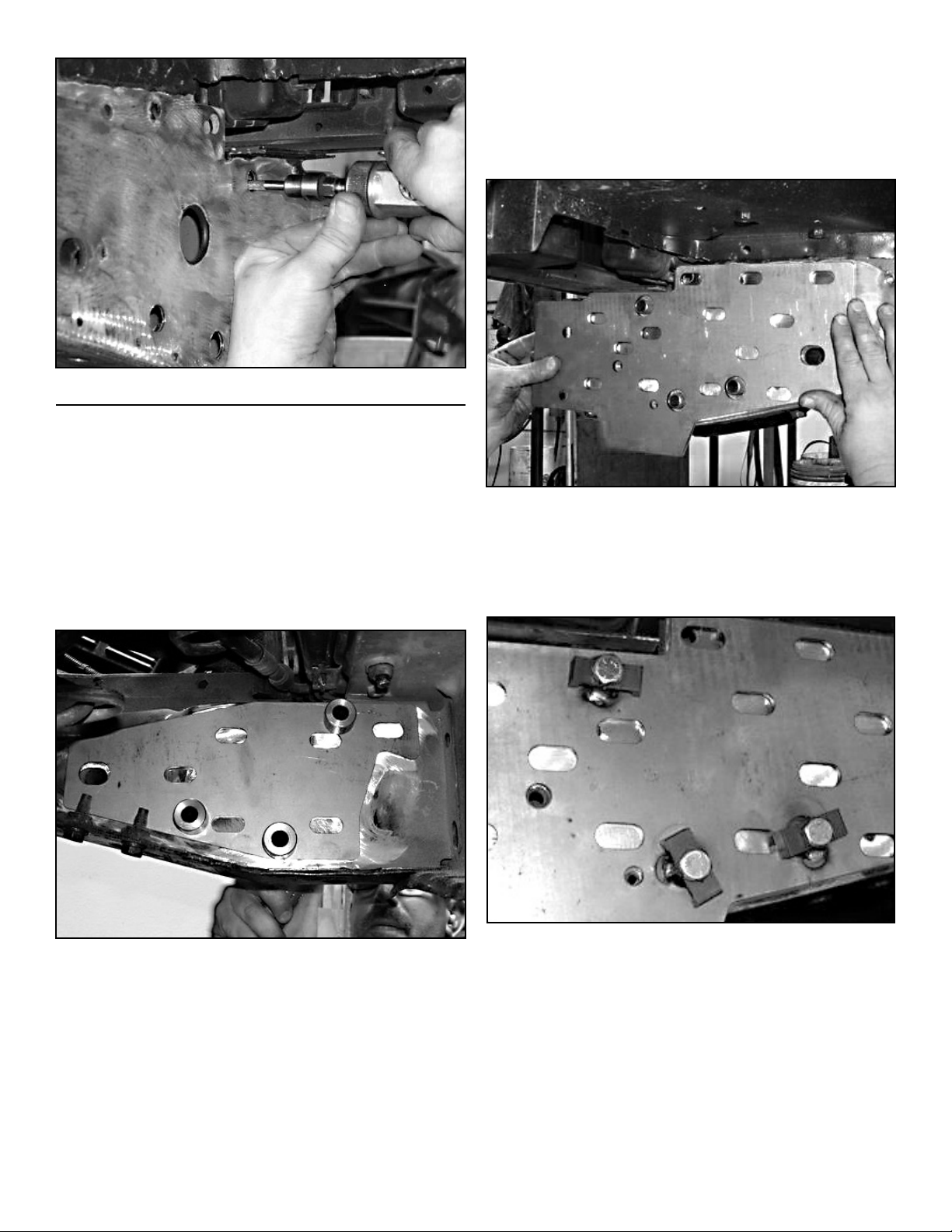
ZEnlarge the inboard and outboard mounting holes
to approximately 5/8” – or until narrow end of Sup-
port Sleeves (C) can be inserted.
HINT: A uni-bit (step-drill bit) is useful for enlarging
holes to 5/8” – and more eective on the unibody
chassis than standard drill bits. A pneumatic die
grinder or dremel tool with carbide cutting attach-
ment (shown) is also eective, particularly where
clearance is limited.