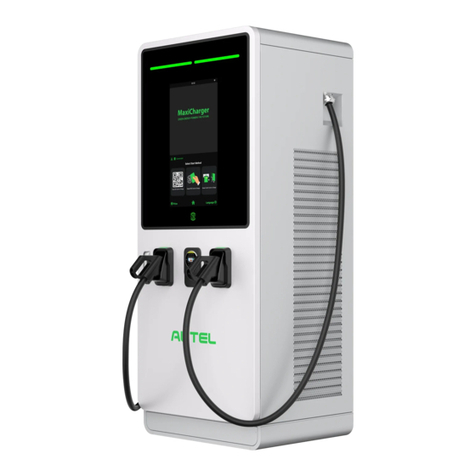
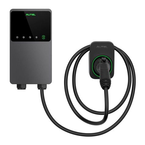
Autel MaxiCharger AC Wallbox Home User manual

i
Trademarks
Autel
®
and MaxiCharger
®
are trademarks of Autel Intelligent Technology Corp., Ltd.,
registered in China, the United tates and other countries. All other marks are trademarks
or registered trademarks of their respective holders.
Copyright Information
No part of this manual may be reproduced, stored in a retrieval system or transmitted, in any
form or by any means, electronic, mechanical, photocopying, recording, or otherwise without
the prior written permission of Autel.
Disclaimer of Warranties and Limitation of Liabilities
All information, specifications and illustrations in this manual are based on the latest
information available at the time of printing.
Autel reserves the right to make changes at any time without notice. While information of
this manual has been carefully checked for accuracy, no guarantee is given for the
completeness and correctness of the contents, including but not limited to the product
specifications, functions, and illustrations.
Autel will not be liable for any direct, special, incidental, indirect damages or any economic
consequential damages (including the loss of profits).
IMPORTA T
Before operating or maintaining this unit, please read this manual carefully, paying extra
attention to the safety warnings and precautions.
For Services and Support:
Web: www.autelenergy.com
Tel: +49 (0) 89 540299608 (Europe)
0086-755-2267-2493 (China)
Email: [email protected]
For technical assistance in all other markets, please contact your local selling agent.

ii
Safety Information
For your own safety and the safety of others, and to prevent damage to the device and
vehicles upon which it is used, it is important that the safety instructions presented
throughout this manual be read and understood by all persons operating or coming into
contact with the device.
Safety Messages
afety messages are provided to help prevent personal injury and equipment damage. All
safety messages are introduced by a single word indicating the hazard level.
DA GER
Indicates an imminently hazardous situation which, if not avoided, will result in death or
serious injury to the operator or to bystanders.
WAR I G
Indicates a potentially hazardous situation which, if not avoided, could result in death or
serious injury to the operator or to bystanders.
Safety Instructions
The safety messages herein cover situations Autel is aware of. Autel cannot know, evaluate
or advise you as to all of the possible hazards. You must be certain that any condition or
service procedure encountered does not jeopardize your personal safety.
SAFETY WAR I GS
Read all the instructions before you use this device.
Do not install or use the device near flammable, explosive, harsh, or combustible
materials, chemicals, or vapors.
Turn off power at the circuit breaker before installing or cleaning the device.
This device should be supervised when used around children.
This device must be grounded through a permanent wiring system or an equipment-
grounding conductor.
Use the device only within the specified operating parameters.
Do not use the device if it is defective, appears cracked, frayed, broken or otherwise
damaged, or fails to operate.
Do not use the device if the flexible power cord or EV cable is frayed, broken, or
otherwise damaged, or if it fails to operate.
Do not attempt to disassemble, repair, tamper with or modify the device.
iii
Handle the device with care during transportation. Do not subject it to strong force or
impact, pull, twist, tangle, drag or step on the device, to prevent damage to it and any
of its components.
Do not insert fingers or foreign objects into any part of the device.
If any specifications or regulations mentioned in this manual contradict with your
local rules, refer to your local rules.
CAUTIO
Do not use private power generators as a power source for charging.
Incorrect installation and testing of the device could potentially damage the vehicle's
battery, components, and/or the device itself.
Do not operate the device in temperatures outside its operating range.

iv
CO TE TS
SAFETY I FORMATIO ................................................................................ II
SAFETY MESSAGES .................................................................................... II
SAFETY I STRUCTIO S .............................................................................. II
1
USI G THIS MA UAL ................................................................................... 1
1.1
CONVENTION ........................................................................................ 1
2
GE ERAL I TRODUCTIO .......................................................................... 3
2.1
PRODUCT OVERVIEW .............................................................................. 4
2.2
OPTION ............................................................................................... 6
2.3
DE CRIPTION OF THE DI PLAY ................................................................. 8
2.3.1
Boot Screen ................................................................................. 8
2.3.2
Standby/Authorization Screen ..................................................... 9
2.3.3
Preparing to Charge Screen ........................................................ 9
2.3.4
Charging Screen ....................................................................... 10
2.3.
Transaction Details Screen ........................................................ 10
2.3.6
Device Information Screen ........................................................ 11
2.3.7
Error Screen .............................................................................. 11
2.4
WIRING DIAGRAM FOR THE MCB, RCD, AND EMERGENCY TOP ............... 13
2.5
PECIFICATION ................................................................................... 15
2.6
PRODUCT MODEL ................................................................................. 20
3
I STALLATIO ............................................................................................ 21
3.1
PREPARE FOR IN TALLATION .................................................................. 21
3.1.1
Preliminary Requirements ......................................................... 21
3.1.2
Unpack the Charger .................................................................. 21
3.1.3
Prepare for Installation .............................................................. 21
3.2
MECHANICAL IN TALLATION .................................................................. 21
3.2.1
Parts and Tools .......................................................................... 22

v
3.2.2
Install the Charger ..................................................................... 23
3.3
POWER UPPLY WIRING ...................................................................... 27
3.3.1
Remove the Covers ................................................................... 27
3.3.2
Insert the AC Input Cable .......................................................... 28
3.3.3
Connect the AC Input Cable, Single-phase ............................... 28
3.3.4
Connect the AC Input Cable, Three-phase ................................ 29
3.3.
Reinstall the Covers .................................................................. 30
3.3.6
Distribution Box Wiring .............................................................. 30
3.4
PROTECTIVE DEVICE ............................................................................. 31
4
OPERATIO ................................................................................................. 32
4.1
ENERGIZE THE CHARGER ...................................................................... 32
4.2
TART CHARGING ................................................................................ 32
4.2.1
Cable Models ............................................................................ 32
4.2.2
Socket/Shutter Models .............................................................. 32
4.3
TOP CHARGING .................................................................................. 33
4.3.1
Cable Models ............................................................................ 33
4.3.2
Socket/Shutter Models .............................................................. 33
5
TROUBLESHOOTI G A D SERVICE ........................................................ 35
5.1
TROUBLE HOOTING TABLE .................................................................... 35
5.2
ERVICE .............................................................................................. 37
6
COMPLIA CE I FORMATIO .................................................................... 38

1
1
Using This Manual
This manual describes the installation and use of the MaxiCharger AC Wallbox Home. Prior
to installation, read through this manual to be familiarized with the instructions of this
MaxiCharger to ensure a successful installation and smooth operations.
1.1 Conventions
The following conventions are used.
Bold Text
Bold text is used to highlight selectable items such as buttons and menu options.
Example:
Tap OK.
otes and Important Messages
otes
A OTE provides helpful information such as additional explanations, tips, and comments.
Example:
OTE
The images and illustrations depicted in this manual may differ slightly from the actual ones.

2
Important
IMPORTA T indicates a situation which, if not avoided, may result in damage to the test
equipment or vehicle.
Example:
IMPORTA T
The charger should only be installed by personnel who are trained and qualified to work on
electrical systems.
Hyperlink
Hyperlinks or links that take you to other related articles, procedures, and illustrations are
available in electronic documents.
Illustrations
Illustrations used in this manual are only examples; the actual product(s) or screens may
vary.

3
2
General Introduction
The MaxiCharger AC wallbox is designed to charge an electric vehicle (hereinafter called
EV). Our chargers provide you with safe, reliable, fast, and smart charging solutions.
This manual will instruct you how to install and use this charger.
Intended Use
The MaxiCharger is intended for the AC charging of EVs. It is intended for both indoor and
outdoor use.
Residential
Commercial
Workplace
Vehicle Workshop
DA GER
1. If you use the equipment in any way other than described in this manual or other related
documents, possible death, injury and damage to property can occur.
2. Use the equipment only as intended.
OTE
1. This manual is for cable, socket, and shutter models. The illustrations in this manual
use the socket version as an example.
2. The images and illustrations depicted in this manual may differ slightly from the actual
ones.

4
2.1 Product Overview
MaxiCharger AC Wallbox
1. LED Indicators (from left to right):
Power LED
Internet Connection LED
Charging LED
Bluetooth Connection LED
2. RFID Reader
3. AC Input Cable
4. RJ45 Ethernet Port
5. Mounting crews
6. Rear Entry ignal Conduit Plug
7. Rear Entry Power Conduit Plug
8. Product Label

5
LED Description
LED Description
Power LED
Solid Green: The charger is on.
Off: The charger is off.
Flashing Yellow: Data is being transmitted and/or firmware
is upgrading.
Solid Yellow: Firmware upgrade has failed.
Solid Blue: Data transmission has failed; will turn solid green
in five seconds (see above).
Internet
Connection LED
Solid Green: The charger is connected to the Internet.
Off: The charger is not connected to the Internet.
Flashing Green: The charger has joined the DLB (Dynamic
Load Balancing) network.
Charging LED
Solid Blue: An EV is connected.
Flashing Blue: A schedule is active.
Flashing Cyan: The charger is reserved.
Flashing Green: An EV is charging.
Solid Orange: A recoverable error has occurred.
Solid Green: A charge session has ended.
Off: No EV connected.
Solid Red: An irrecoverable error has occurred. (Please
contact support.)
Bluetooth
Connection LED
Flashing Green: The charger is connected to a mobile device
via Bluetooth.
Flashing Blue: The charger is connected to VCI (Vehicle
Communication Interface) via Bluetooth.
Flashing Cyan: The charger is connected to a mobile device
and a VCI device simultaneously via Bluetooth.
Off: The charger is not connected via Bluetooth.

6
2.2 Options
Display
A. Ambient Light ensor — detects ambient brightness
B. Display
C. Energy Pulse Output (Infrared Ray)
D. IM Card ocket
(Available on chargers with 4G function.)

7
Cable Model
E. Charging Handle afety Lock — Press to release charging handle from its cradle
F. Charging Handle, Type 2
G. Cradle
H. EV Charge Cable
(With holster) (Without holster)
OTE
Drape the EV charge cable over the top of the MaxiCharger and dock the connector in
its holster when not in use. ee the figure above.
The maximum length of the EV charge cable is 7.5 meters.
Socket/Shutter Model
I. ocket/ hutter, Type 2

8
2.3 Description of the Display
IMPORTA T
This section is only applicable to chargers with a display.
Function Buttons
Button Description
Cost Details Tap to view the charging cost.
Language Tap to choose your language for the charger.
Stop Tap to stop a charge session.
OK Tap to confirm the information on the screen.
Back Tap to return to the previous screen.
2.3.1 Boot Screen
The display shows the Boot screen while the charger starting up.

9
2.3.2 Standby/Authorization Screen
1. Top screen — displays total delivered energy, time, signal strength, and Bluetooth
connection
2. Middle screen — provides two authorization methods: QR code or RFID card
3. Bottom screen — tap to view the charging costs and choose your language
The display shows the tandby/Authorization screen when the charger is in idle status,
indicating that the charger is ready for use. When this screen appears, choose an
authorization method (QR code or RFID card) to start a charge session.
2.3.3 Preparing to Charge Screen

10
2.3.4 Charging Screen
The Charging screen appears during the charge session.
1. Top screen
2. Main Charging screen — shows the real-time charging progress, the OC value, and
other charging information including energy, duration, current cost, power, voltage, as
well as current per phase.
3. top button — tap to stop the charge session
2.3.5 Transaction Details Screen
When the charge session ends, the Transaction Details screen will appear.
Tap the OK button to confirm your transaction details.

11
2.3.6 Device Information Screen
The actual Device Information screen may differ.
2.3.7 Error Screen
The display shows different error messages depending on the error type.
The charger fails to start a charge session:
Tap the OK button to confirm the message.

12
An error has occurred with the charger. Contact Autel support.

13
2.4 Wiring Diagram for the MCB, RCD, and
Emergency Stop
Figure 2-1 MCB + RCD + Emergency Stop View (for 7. kW device)
Figure 2-2 MCB + RCD + Emergency Stop View (for 11/22 kW device)

14
Figure 2-3 Connection Diagram
The actual connection among the MCB, RCD, emergency stop, and the charger are as
shown above. This diagram applies to 7.5 kW, 11 kW, and 22 kW models.
1. MCB + RCD
2. Emergency top

15
2.5 Specifications
Item Description
Product Information
Charging Type Mode 3 charging
Input/Output Power
Rating and Current
ingle-phase: 7.4 kW/32 A
Three-phase: 11 kW/16 A
Three-phase: 22 kW/32 A
Protection
Over-current, over-temperature,
over-voltage, under-voltage,
ground fault including DC
residual current protection,
integrated surge protection
Earth (Ground) Fault
Protection 30 mA AC and 6 mA DC
Input/Output Voltage
230 V ±15%, single phase
400 V ±15%, three phase
50 Hz
Network Type TT, TN
General Characteristics
IP and IK Rating Cable model: IP65; IK08
ocket/shutter model: IP54; IK08
Operating Altitude 2,000 m
Humidity < 95 % RH, non-condensing
Operating
Temperature Range
-40 °C to + 55 °C
torage
Temperature Range
-40 °C to + 85 °C
Mounting Wall or floor using a pedestal
Dimensions
(
H × W × D
)
Cable: 336 x 187 x 85 mm
ocket/shutter:
336 × 187 × 115 mm
Other manuals for MaxiCharger AC Wallbox Home
1
Table of contents
Other Autel Automobile Accessories manuals

Autel
Autel MaxiIM TOYOTA 8A BLADE KEY User manual

Autel
Autel MaxiIM TOYOTA 8A BLADE KEY User manual

Autel
Autel MaxiVCI V150 User manual

Autel
Autel MaxiCharger DC Fast User manual

Autel
Autel MaxiTPMS TS508 User manual

Autel
Autel APB112 User manual

Autel
Autel Maxi US AC W12-H User manual

Autel
Autel ATS100 User manual
Popular Automobile Accessories manuals by other brands

Cruz
Cruz N+ Series Assembly instructions

Free2Move eSolutions
Free2Move eSolutions eProWallbox Series Configuration guide

AUSSIE TONNEAU
AUSSIE TONNEAU ATB01138 FITTING INSTRUCTION

Michel's
Michel's Gravel Guard manual

Ranger design
Ranger design 1525-TC installation guide

Prorack
Prorack K621 Fitting instructions