Ectron 441A User manual

INSTRUCTION MANUAL
MODEL 441A
FREQUENCY-TO-VOLTAGE
CONVERTER
The information contained in this manual is proprietary. Permission to reproduce all or
part must first be obtained in writing from this company.
Ectron Corporation reserves the right to make specification changes at any time.
LIFE-SUPPORT POLICY: Ectron products are not authorized for use in life-support
devices or systems without the express, written approval of the President of
Ectron Corporation.
Copyright 1996 Ectron Corporation
Ectron Corporation 8159 Engineer Road
All rights reserved San Diego, CA 92111-1907
U.S.A.
Revised September, 2015 858-278-0600
800-732-8159
For units with serial numbers
62230 and above. Fax: 858-278-0372
www.ectron.com

All Ectron instruments are warranted against defects in material and workmanship for one year
from the date of shipment to the original purchaser. Ectron agrees to repair or replace any
assembly or components (except expendable items such as fuses, lamps, batteries, etc.) found to
be defective during this period. Ectron's obligation under this warranty is limited solely to
repairing or replacing, at its option, an instrument that in Ectron's sole opinion proves to be
defective within the scope of the warranty when returned to the factory or to an authorized
service center. Transportation to the factory or service center is to be prepaid by the purchaser.
Shipment should not be made without the prior authorization of Ectron. This warranty does not
apply to products repaired or altered by persons not authorized by Ectron, or not in accordance
with instructions furnished by Ectron. If the instrument is defective as a result of misuse,
improper repair, alteration, neglect, or abnormal conditions of operation repairs will be billed at
Ectron's normal rates. Ectron assumes no liability for secondary charges of consequential
damages as a result of an alleged breach of this warranty; and in any event, Ectron's liability for
breach of warranty under any contract or otherwise shall not exceed the purchase price of the
specific instrument shipped and against which a claim is made. This warranty is in lieu of all
other warranties, expressed or implied; and no representative or person is authorized to represent
or assume for Ectron any liability in connections with the sale of our products other than is set
forth herein.
If a fault develops, notify Ectron or its local representative, giving full details of the difficulty.
Include the model and serial numbers. On receipt of this information, a service date or shipping
instructions will be furnished. If shipment is indicated, forward the instrument, freight prepaid,
to the factory or to the authorized service center indicated in the instructions.
Instruments should be tested upon receipt. If there is any damage, a claim should be filed with
the carrier. A full report of the damage should be obtained by the claim agent, and that report
should be forwarded to Ectron. Ectron will advise the disposition to be made of the equipment
and arrange for repair or replacement. Please include model and serial numbers in all
correspondence.
GENERAL
PROCEDURE FOR SERVICE
DAMAGE IN TRANSIT
®

Table of Contents
PAGE
Warranty Inside Front Cover
Section I, Description
General 1-1
Features 1-1
About this Manual 1-3
Abbreviations 1-4
Section II, Specifications
General 2-1
Input 2-1
Output 2-2
Frequency-to-voltage Conversion 2-3
Calibration 2-4
Alignment 2-4
Front Panel 2-4
Retention of Settings 2-4
Input Power 2-4
Environment 2-5
Dimensions 2-5
Compatibility 2-5
Section III, Operation
General 3-1
Connections 3-1
Operational-state Diagram 3-1
Limits vs Settings 3-4
View Angle 3-4
Controlling the Model 441A 3-4
Operate Screen 3-6
Frequency-set Screen 3-6
Voltage-set Screen 3-7
Input-signal Screens 3-7
Pulses/Revolution Screen 3-7
Input-sensitivity Screen 3-8
Input-B/W (Filter) Screen 3-9
Output-filter Screen 3-9
i

Cal Screen 3-10
Secondary Screens 3-10
Ten-volt Alignment 3-11
Reset 3-12
Enclosures 3-13
Model E408-1 3-13
Model E408-6 3-13
Model R408-14 3-14
Section IV, Applications
General 4-1
Input-signal Conditioner 4-1
Input Signal, Grounding, and Shielding 4-1
Emi Protection 4-2
Frequency-to-analog Conversion 4-2
Output Analog Filter and Output Stage 4-2
Frequency and Voltage Set Points 4-2
Noise 4-3
Uncertainty and Resolution 4-5
Filtering 4-8
Input Bandwidth Filter 4-8
Output Filter 4-9
Digital Filter 4-9
Selectable Input Sensitivity 4-12
Response Time 4-12
Update Rate 4-12
Latency 4-13
Front-panel Indication 4-13
Calibration 4-13
Vehicle Applications 4-14
Section V, Theory of Operation
General 5-1
Signal Conditioning (Hardware) 5-2
Frequency Measurement (Firmware) 5-2
Transfer Function (Firmware) 5-2
Output Stages (Hardware) 5-2
Power Supplies (Hardware) 5-3
PAGE
Table of Contents Model 441A
ii

Section VI, Calibration
Equipment Required 6-1
Pre-calibration 6-1
Alignment 6-4
Post-calibration 6-5
Optional Calibration Tests 6-5
Ectron Model 441A Calibration Test Report 6-7
Section VII, Parts Lists
Names of Manufacturers 7-1
Model E408-6 Enclosure 7-2
Model R408-14 Enclosure 7-3
Figures
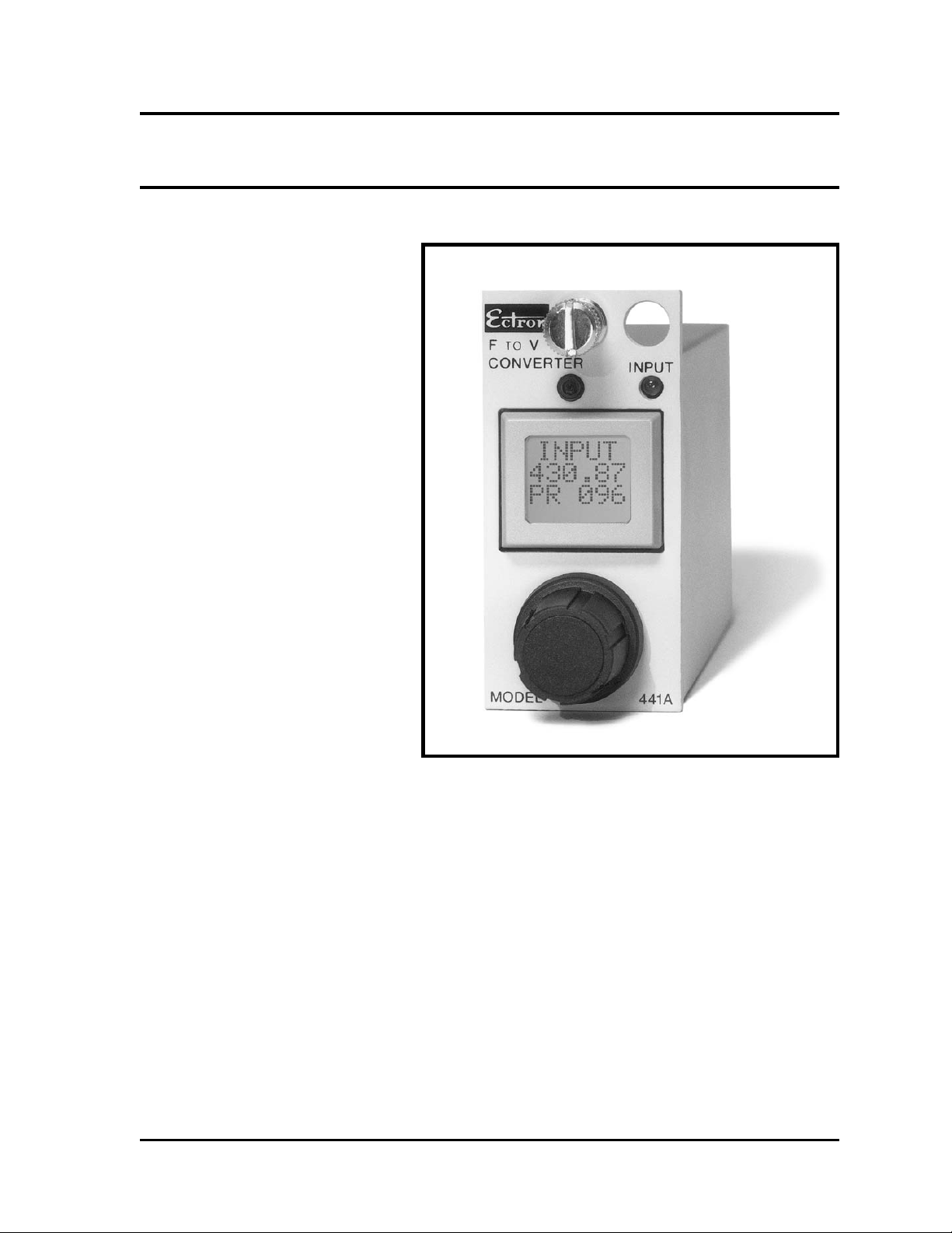
Model 441A 1-1
Figure 3-1, Operational-state Diagram 3-2
Figure 3-2, View-angle Screens 3-4
Figure 3-3, Operate Screen 3-6
Figure 3-4, Frequency-set Screen 3-6
Figure 3-5, Voltage-set Screen 3-7
Figure 3-6, Pulses/Revolution Screen 3-8
Figure 3-7, Input-sensitivity Screen 3-8
Figure 3-8, Input-bandwidth Screen 3-9
Figure 3-9, Output-filter Screen 3-9
Figure 3-10, CAL Screen 3-10
Figure 3-11, Adjust 10 V Screen 3-11
Figure 3-12, Alignment-required Screen 3-11
Figure 3-13, Memory-error Screen 3-12
Figure 3-14, Reset Screen 3-12
Figure 4-1, Maximum Uncertainty for
Various Frequencies 4-4
Figure 4-2, Worst-case Resolution for
Various Frequencies 4-5
Figure 4-3, Maximum of Uncertainty and
Resolution for Various Frequencies 4-6
Figure 4-4, Maximum Output Noise
with a 10 mV Sine-wave Input 4-7
Figure 4-5, Maximum Output Noise
with a 1 V Sine-wave Input 4-8
Figure 4-6, Effects of the Digital
(Periodic-error) Filter 4-10
PAGE
Model 441A Table of Contents
iii

Figure 4-7, Filtering Scheme for ABS Testing 4-11
Figure 4-8, Filter Circuit for ABS Testing 4-12
Figure 4-9, Strip-chart Recording of ABS Action 4-13
Figure 5-1, Model 441A Block Diagram 5-1
Figure 6-1, Frequency-range Setup 6-2
Figure 6-2, Frequency-calibration Setup 6-3
Figure 6-3, Alignment 6-4
Figure 6-4, Optional Tests 6-5
Tables
Table 1-1, Abbreviations in This Manual 1-4
Table 2-1, Input Bandwidth and
Sensitivity Settings 2-1
Table 2-2, Front-panel Screens 2-6
Table 3-1, Connector-pin Assignments 3-1
Table 3-2, Default Settings and Limits 3-3
Table 4-1, Input Frequency vs
Output Voltage (Example) 4-3
Table 4-2, Response Time Versus Output Filter Setting 4-9
Table 6-1, Input Sensitivity 6-6
Table 7-1, List of Manufacturers 7-1
Schematics and Drawings
Model E408-6Y (Internal 12 V dc Power Supply) 408-600
Model E408-6X (Internal 28 V dc Power Supply) 408-601
Model R408-14Y (Internal 12 V dc Power Supply 408-605
Model R408-14X (Internal 28 V dc Power Supply 408-606
Model 441A Outline Dimensions 441-901
Model E408-1 Outline Dimensions 408-900
PAGE
Table of Contents Model 441A
iv
Section I
Description
GENERAL
The Model 441A produces an ana-
log voltage that precisely repre-
sents the frequency of an applied
input signal. Adjustable “input fre-
quency to output voltage” set
points allow the user to quickly
bracket the frequency of interest.
A unique crystal-controlled micro-
controller design provides fast re-
sponse, high conversion accuracy,
and low output noise that is inde-
pendent of frequency. In the oper-
ate mode, the front-panel display
shows the input frequency with up
to five-digit resolution. All oper-
ating parameters are set using the
display and only one other front-
panel control. It’s that easy. The
input-signal conditioner automat-
ically provides stable operation for
a wide range of pulse-, square-, and
sine-wave signals from under
10 mV to 100 V.
FEATURES
Reliable “state of
the art” design
The Model 441A combines the same rugged construc-
tion used in the Ectron 400 Series product line for the
last 30 years with the latest electronic and surface-mount
technology to produce a true breakthrough in frequency-
to-voltage conversion.
Designed in are rapid response to any change in fre-
quency, low output noise that is independent of input
frequency, and input-signal conditioning that automat-
ically provides correct operation for a great variety of
input signals, both in wave shape and amplitude.
Simplicity Gone is the clutter of switches, knobs, pots, etc. asso-
ciated with other frequency-to-voltage converters. All
Model 441A
Frequency-to-voltage Converter
1-1

has been replaced with two easy-to-use controls that
allow complete control: the display and the encoder.
Display The backlit digital display has the dual function of dis-
play and screen selection. Nine easy-to-use setup
screens, four less frequently used screens, as well as
the operate screen are accessible to the user at the touch
of the display.
Encoder With just this one additional control, the user can com-
pletely and easily configure the Model 441A to precisely
what the situation requires. The encoder also has a dual
purpose: character selection and change.
Wide range of applications With an input-frequency range of 1 Hz to 50 kHz and
an output-voltage range of −10 V to +10 V, the user
can employ the Model 441A to study a wide variety of
frequency-producing equipment. This is in keeping with
Ectron’s intent to provide instruments with wide appli-
cation for the serious user.
Power The Model 441A operates from any dc power from
10.5 V to 32 V. This simplifies test-configuration setup
for the user and may even reduce the cost if fewer power
sources are required.
Model 441AL versus
Model 441A
The Model 441AL incorporates a fixed-gain logic-level
input detector instead of the input automatic gain control
(AGC) of the Model 441A. The Model 441AL is de-
signed to operate with fixed-level input signals with rela-
tively sharp rise and fall times. The input can be set to
accommodate levels of 0 V to 5 V, 0 V to 25 V, and
0 V to 100 V.
The fixed gain of the Model 441AL input stage reduces
the delay in responding to an abruptly starting input
signal unlike the AGC circuit, which has a hard time
responding quickly to an input signal that starts sud-
denly. AGC timing is a compromise between fast re-
sponse and noise immunity. As a result the AGC may
not keep up with a rapidly rising input amplitude: the
Model 441A may not respond to this signal for several
hundred milliseconds. A similar situation exists for a
rapidly falling input amplitude. These delays are reduced
to one millisecond plus one period of the input signal
in the Model 441AL since no AGC stage is present.
Enclosures Because the Model 441A uses the same connector as
all other 400 Series products, it can be used in all Ectron
enclosures designed for this product line — even inter-
mixed with Model 428 and 352 conditioner-amplifiers
and Model 451 LVDT-signal conditioner. The Model
441A uses the same input and output pins as do these
Description Model 441A
1-2

other products, so the user who has existing hardware
in place can remove an amplifier-conditioner and plug
in the frequency-to-voltage converter and start using it
immediately.
ABOUT THIS MANUAL
The following sections are in this manual:
Specifications This is a complete technical description of the
Model 441A and the performance that is guaranteed.
While the performance specifications are the best in fre-
quency-to-voltage conversion, they are conservative.
The user may find that a particular unit will perform
well beyond specification.
Operation Here the user will find complete instructions to use the
Model 441A. Pictures of all the screens and an
operational-state diagram enhance the discussion. Also
discussed are the various enclosures available for the
Model 441A and other 352 and 400 Series units.
Applications Because the Model 441A is designed as a universal fre-
quency-to-voltage converter, it would be impossible to
address every possible use for this product. Rather, this
section is written to help the user get the most from the
data resulting from using the Model 441A. Concerns
about cabling, shielding, common-mode voltage, etc. are
addressed.
Theory of operation Because the Model 441A is an encapsulated unit, repair
in the field is strongly discouraged. Therefore, a detailed
circuit analysis is foregone in this manual. However,
theory at the block-diagram level as well as a discussion
of internal software is presented to further aid the user
in operating the frequency-to-voltage converter for best
performance.
Calibration Step-by-step instructions are given to test the Model
441A against its specifications. A brief overview of each
test is given to give the technician further insight into
each test performed.
Drawings Schematic diagrams of several enclosures are included
to aid the user in instrumentation configuration.
Warranty The warranty for this product is on the inside of the
front cover.
Model 441A Description
1-3
ABBREVIATIONS
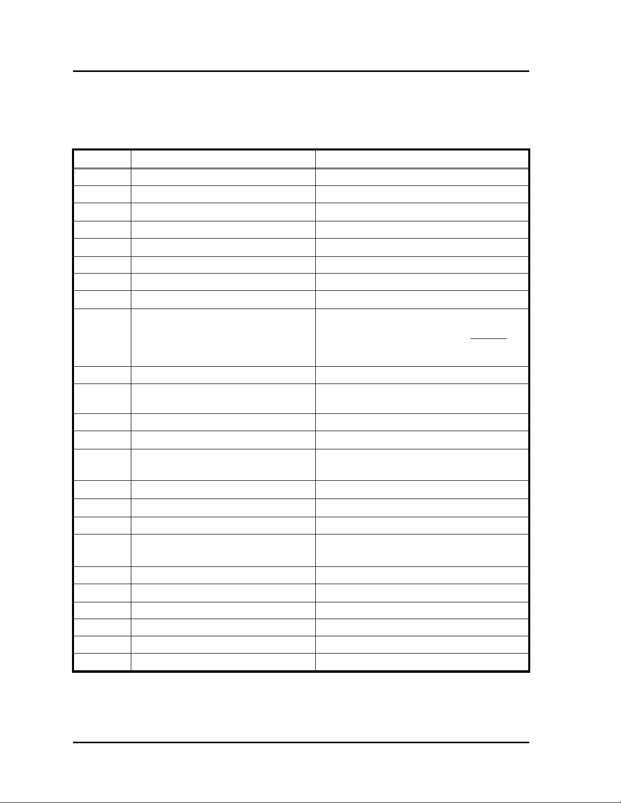
Table 1-1 lists the abbreviations used throughout the manual.
Table 1-1
Abbreviations in This Manual
Symbol Meaning Typical use
ac Alternating current 120 V ac
A Ampere Power current = 150 mA
C Centigrade 50°C
dc Direct current 10.5 V dc to 32 V dc
°Degree 50°C
fco Filter cutoff frequency fco = 100 Hz
fin Input frequency fin can be 1 Hz to 50 kHz
F Farad Input Impedance = …300 pF…
fUUpper-frequency set point Volts-per-hertz resolution = VU−VL
fU−fL
fLLower-frequency set point See fU
g Gravitational force, gram Shock resistance = 20 g
Weight = 270 g
Hz Hertz (cycles per second) fin can be 1 Hz to 50 kHz
kKilo (1 ×10³)Maximum frequency = 50 kHz
MMega (1 ×10⁶)Noise-measurement
bandwidth = …1 MHz
mMilli (1 ×10⁻³), meter Width = 28.4 mm
ΩOhm Output impedance = 1 Ω …
oz Ounce Weight = 9 oz, nominal
pPeak, pico (1 ×10⁻¹²)Input sensitivity ≥10 mV p
Input Impedance = …300 pF…
p-p Peak to peak 20 V p-p output capability
s Second Update rate = 1 ms …
V Volt or voltage 10 mV to 100 V input
VUUpper-voltage set point See fU
VLLower-voltage set point See fU
″Inch Length = 4″
Description Model 441A
1-4

Section II
Specifications
GENERAL
All specifications apply over the temperature range of 0°C to 50°C unless otherwise specified,
and they are the maximum deviation allowed from ideal unless otherwise noted. Table 1-1
lists the various symbols and their respective meanings that are used throughout this manual.
INPUT
Configuration Differential with a common-mode-voltage rating of up
to 100 V dc or peak ac.
Impedance 200 kΩin parallel with 300 pF nominal.
Frequency range 1 Hz to 50 kHz.
Sensitivity and bandwidth Three steps of input sensitivity and three steps of in-
put-bandwidth control are provided to optimize input
signal-to-noise ratio.
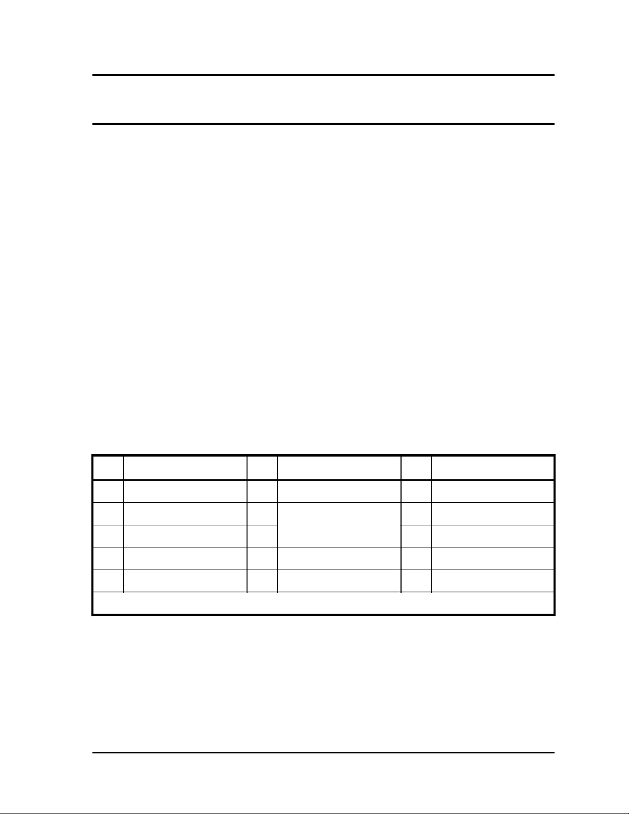
Table 2-1
Input Bandwidth and Sensitivity Settings
Screen MIN MID MAX
Input B/W 10 Hz 500 Hz Wideband
Input Sensitivity 200 mV peak 25 mV peak 10 mV peak
All settings are nominal.
Periodic-error filtering A periodic-error filter can be activated for input signals
that are less than 1 kHz. By entering the pulses per
revolution (cycle), the user can eliminate erroneous vari-
ations of periodicity. Two to 999 pulses can be accom-
modated.
Square- and sine-wave
amplitude range
10 mV to 100 V peak.
Pulse amplitude range 40 mV to 100 V peak (2.5% to 97.5% duty cycle, 5 µs
minimum pulse width).
Response to rapid
change in amplitude
The Model 441A will recover and provide the proper
output within 0.2 s +1⁄fin following a 10:1 change in
amplitude of the input signal, where fin is the frequency
of the input signal.
2-1

OUTPUT
Voltage (V)The linear range of the analog output is from −10 V to
+10 V with up to 10 mA current. The output limits are
approximately ±10.5 V. Output voltage for a given fre-
quency is determined by voltage and frequency set
points using the following:
V=VU−VL
fU−fL×(fin −fL)+VL,
where fin is the input frequency and VUand VLand fU
and fLare the upper and lower voltage and frequency
settings of the instrument, respectively.
Uncertainty (VUNC)For frequencies less than 1 kHz,
VUNC =0.00122 +
fin2
1.5 ×10⁶−fin ×VU−VL
fU−fL
,
where fin is the input frequency and VUand VLand fU
and fLare the upper and lower voltage and frequency
settings of the instrument, respectively.
For frequencies of 1 kHz and above,
VUNC =0.00122 +
fin2
(1.5 ×10⁶)F×VU−VL
fU−fL
,
where fin is the input frequency, Fis fin ⁄1000 rounded up
to the nearest integer, and VUand VLand fUand fLare
the upper and lower voltage and frequency settings of
the instrument, respectively.
Uncertainty (Hz)The uncertainty of the output in terms of frequency is
Hz =VUNC ×fU−fL
VU−VL,
where VUNC is the uncertainty in volts, and VUand VL
and fUand fLare the upper and lower voltage and fre-
quency settings of the instrument, respectively.
Scaling
V
Hz
V
Hz =VU−VL
fU−fL,
where VUand VLand fUand fLare the upper and lower
voltage and frequency settings of the instrument, re-
spectively.
Resolution (R)For input frequencies below 1 kHz, the resolution at
the output is:
Specifications Model 441A
2-2

R=0.00122 V or
fin2
1.5 ×10⁶−fin ×VU−VL
fU−fL
,
whichever is greater, where fin is the input frequency,
VUand VLare the voltage settings, and fUand fLare
the frequency settings.
For input frequencies at or above 1 kHz, resolution in
volts at the output is:
0.00122 V or
fin2
(1.5×10⁶)F×VU−VL
fU−fL
,
whichever is greater, where fin is the input frequency,
Fis fin ⁄1000 rounded up to the nearest integer, VUand
VLare the voltage settings, and fUand fLare the fre-
quency settings.
Impedance Less than 1 Ωat dc.
Noise Less than or equal to 10 mV p-p independent of input
frequency measured with a bandwidth of 0.1 Hz to
1 MHz. For slower rise-time signals such as sine waves,
output noise depends on input-signal noise and ampli-
tude since accurate timing is hampered by noise.
Response time Response to an abrupt frequency change is
0.005 s +1⁄fin, where fin is the frequency of the input,
with the filter set to wideband. For other filter frequen-
cies, add 5⁄fco, where fco is the filter cutoff frequency.
Update rate 0.001 s or 1⁄fin, where fin is the frequency of the input,
whichever is a longer period of time.
Latency The output will start to respond to a change in input
frequency within 1 ms of each falling edge of the input
signal for input frequencies above 1 kHz and within
1 ms +1⁄fin, where fin is the frequency of the input, for
frequencies below 1 kHz.
Filter Selectable filter frequencies of 1 Hz, 10 Hz, and 100 Hz
plus wideband (approximately 1.5 kHz). The filter has
a two-pole Bessel characteristic.
FREQUENCY-TO-VOLTAGE CONVERSION
General Following the input-conditioner-agc circuit, a microcon-
troller converts the input frequency to an equivalent ana-
log signal. The output is then scaled to a 14-bit DAC
based on the user-specified frequency and voltage set
points.
Frequency set points
(upper and lower)
These set points determine the input frequency at which
the upper- and lower-voltage set points are reached. The
Model 441A Specifications
2-3

frequency set points can be any two frequencies between
0 Hz and 50 kHz with a resolution of 1 Hz, and they
can be within 10 Hz of each other.
Voltage set points
(upper and lower)
These set points determine the output voltages corre-
sponding to the upper- and lower-frequency set points,
respectively. The voltage set points can be any two volt-
ages from −10 V to +10 V with a resolution of 0.1 V,
and they can be within 0.1 V of each other (the upper-
voltage set point always being more positive than the
lower voltage set point).
CALIBRATION
When in the calibration mode, an internally generated calibration signal can be set to any
frequency between 1 Hz and 50 kHz in 1 Hz increments. When enabled, the analog output
assumes a value according to the frequency and voltage set points. The calibration signal
can be toggled on and off when in the CAL mode of operation.
ALIGNMENT
Alignment of the Model 441A is performed using the two alignment modes of −10 V and
+10 V. This feature allows field alignment and calibration of the instrument using only a
voltmeter.
FRONT PANEL
Controls The display/push button allows the operator to sequence
through the various setup screens. The round switch,
encoder, has both push-button and rotary action: the
push-button action moves the cursor to the digit to be
changed while the rotary action is used to change the
selected digit. All operating parameters are set using
these controls and are shown on the display.
Input LED The LED on the front panel indicates that a valid input
frequency signal is present and that the output represents
the input frequency.
Display The front-panel back-lit LCD display shows the input
frequency when in the operate mode. Five digits of reso-
lution are indicated — even at lower frequencies. If the
input frequency is unstable the less-significant digits will
vary. Table 2-2 lists all possible screens and their func-
tions.
RETENTION OF SETTINGS
All settings of the Model 441A are retained in nonvolatile memory.
INPUT POWER
Range 10.5 V dc to 32 V dc, unregulated.
Over-voltage protection Up to +60 V for 15 s; +32 V and −50 V, continuously.
Specifications Model 441A
2-4

Current (nominal) 150 mA.
Protection Protected against polarity reversal.
ENVIRONMENT
Emi/rfi Internal rfi filters are provided on all connector leads.
Operating temperature 0°C to +50°C.
Storage temperature −40°C to +80°C.
Altitude No limit with adequate heat dissipation.
Static-acceleration
resistance
200 m⁄s2(approximately 20 g) in any plane.
Shock resistance 200 m⁄s2(approximately 20 g) for 11 ms in any plane.
Vibration resistance 100 m⁄s2(approximately 10 g) in any plane.
DIMENSIONS (SEE DRAWING 441-900)
Height (panel) 60.2 mm (2.37″).
Height (case) 50.8 mm (2.00″).
Width 28.4 mm (1.12″).
Depth 101.6 mm (4.00″).
Weight 255 g (9 oz) nominal.
COMPATIBILITY
The Model 441A will operate in all standard Ectron enclosures designed for Models 352
and 428 conditioner-amplifiers and the Model 451 LVDT-signal conditioner. Current enclosure
products are Models E408-1, E408-6Y, and R408-14Y.
Model 441A Specifications
2-5

Table 2-2
Front-panel Screens
Screen Function
Operate Default screen; input frequency (fin) and pulses per
revolution are displayed.
fUand fLset points Select fUand fLbetween 0 Hz and 50 kHz.
VUand VLset points Select VUand VLbetween −10 V and +10 V.
Pulses/revolution
Select pulses per revolution for input signal less than 1
kHz to eliminate periodic error. This function can be
turned OFF and ON.
Input sensitivity Select input-voltage sensitivity of MIN (200 mV peak),
MID (25 mV p), MAX (10 mV p).
Input bandwidth Select input bandwidth of MIN (10 Hz),
MID (500 Hz), MAX (WB).
Output filter Select output-filter frequency of 1 Hz, 10 Hz, 100 Hz, or
WB.
Calibration Select calibration frequency between 1 Hz and 50 kHz
and turn calibration ON or OFF.
Viewing angle Set screen for best visibility.
Alignment, −10 V Alignment between internal analog
and digital components.
Alignment, +10 V
Memory error Appears only when there is a memory error.
Alignment required Appears only when alignment is required.
Reset Allow user to reset all parameters
to the default settings.
Reset (momentary) Appears for one second after a reset.
Specifications Model 441A
2-6
Section III
Operation
GENERAL
In this section, connections to the Model 441A and the use of its controls are discussed.
The name frequency-to-voltage converter is somewhat misleading in that the real value of
this instrument lies not in its ability to measure frequency—instruments dedicated to that
task do it better—and produce a corresponding voltage output—some frequency-measuring
instruments do this, too—but in its ability to rapidly respond to changes in frequency and
faithfully to produce a corresponding voltage. A more suitable name for the product then
could be “a change in frequency producing a corresponding change in voltage” converter.
This is awkward, so we shorten it.
CONNECTIONS
The Model 441A uses a “D” subminiature fifteen-pin connector for all input and output
connections. Table 3-1 summarizes these connections. These pin assignments are the same
as for Ectron Models 352 and 428 conditioner-amplifiers. Therefore, unless special features
have been incorporated that would preclude using the Model 441A, enclosures designed for
these amplifiers are compatible with the Model 441A including Models E408 and R408.
The Model 441A accepts power from 10.5 V dc to 32 V dc, so enclosures designed for
either 12 V dc or 28 V dc can be used.
OPERATIONAL-STATE DIAGRAM
Figure 3-1 is the operational-state diagram for the Model 441A. Starting at the top of the
diagram all possible screens and operator choices at these screens are depicted. Additionally,
it shows decisions made by the unit during normal operation. These decisions are diagnostic
in nature; and if an error (such as a memory error) occurs, the user will be notified on the
screen of the event.
Table 3-1
Connector-pin Assignments
Pin Function Pin Function Pin Function
1 Input high 6 --- 11 Output low
2 Input low 7* Power high 12 ---
3 Digital output high 8* 13 Case ground
4 Analog output high 9 Input guard 14 ---
5 --- 10 --- 15 Power low
* Pins 7 and 8 are internally connected.
3-1
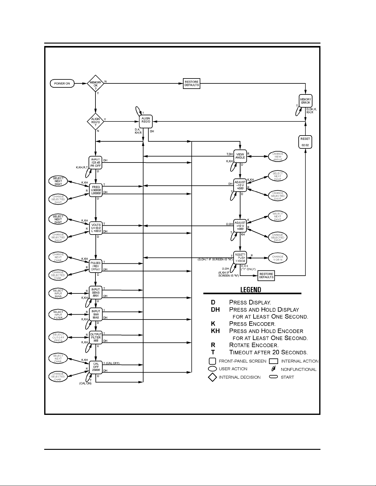
Figure 3-1
Operational-state Diagram
Operation Model 441A
3-2

Table 3-2
Default Settings and Limits
Function Parameter Default Setting Screen Limits
Frequency
Upper set point 50000 Hz
10 Hz to 50000 Hz
and 10 Hz higher
than the lower-
frequency set point
Lower set point 0 Hz
0 Hz to 49990 Hz
and 10 Hz lower
than the upper-
frequency set point
Voltage
Upper set point +10.0 V
−9.9 V to +10 V
and 0.1 V higher
than the lower-
voltage set point
Lower set point 0 V
−10 V to +9.9 V
and 0.1 V lower
than the upper-
voltage set point
Pulses/revolution ON/OFF OFF ON, OFF
Pulses 001 001-999
Input sensitivity Voltage MAX MIN, MID, MAX
Input filter Frequency MAX MIN, MID, MAX
Output filter Frequency WB (wideband) 1 Hz, 10 Hz, 100 Hz
plus WB
CAL ON/OFF OFF ON, OFF
Frequency 25,000 Hz 0 Hz to 50,000 Hz
Alignment −10 V +000 ±750 counts
+10 V +000 ±750 counts
View angle Contrast Midrange Black & blank
Reset Default
settings NO YES, NO
Model 441A Operation
3-3
LIMITS VS SETTINGS
In setting the controls so that a certain frequency corresponds to a certain voltage and another
higher frequency corresponds to a higher (more positive) voltage, the user should always
remember that these set points do not set the limits of operation. Rather they determine the
volts-per-hertz scaling of the output. The limits are fixed at 0 Hz to 63 kHz and −11 V to
+11 V. Table 3-2 lists the default settings and limits for the Model 441A. Except for voltage
alignment, these are the settings of a new unit, and they are the settings (including voltage
alignment) when a RESET is performed. New units are aligned when shipped.
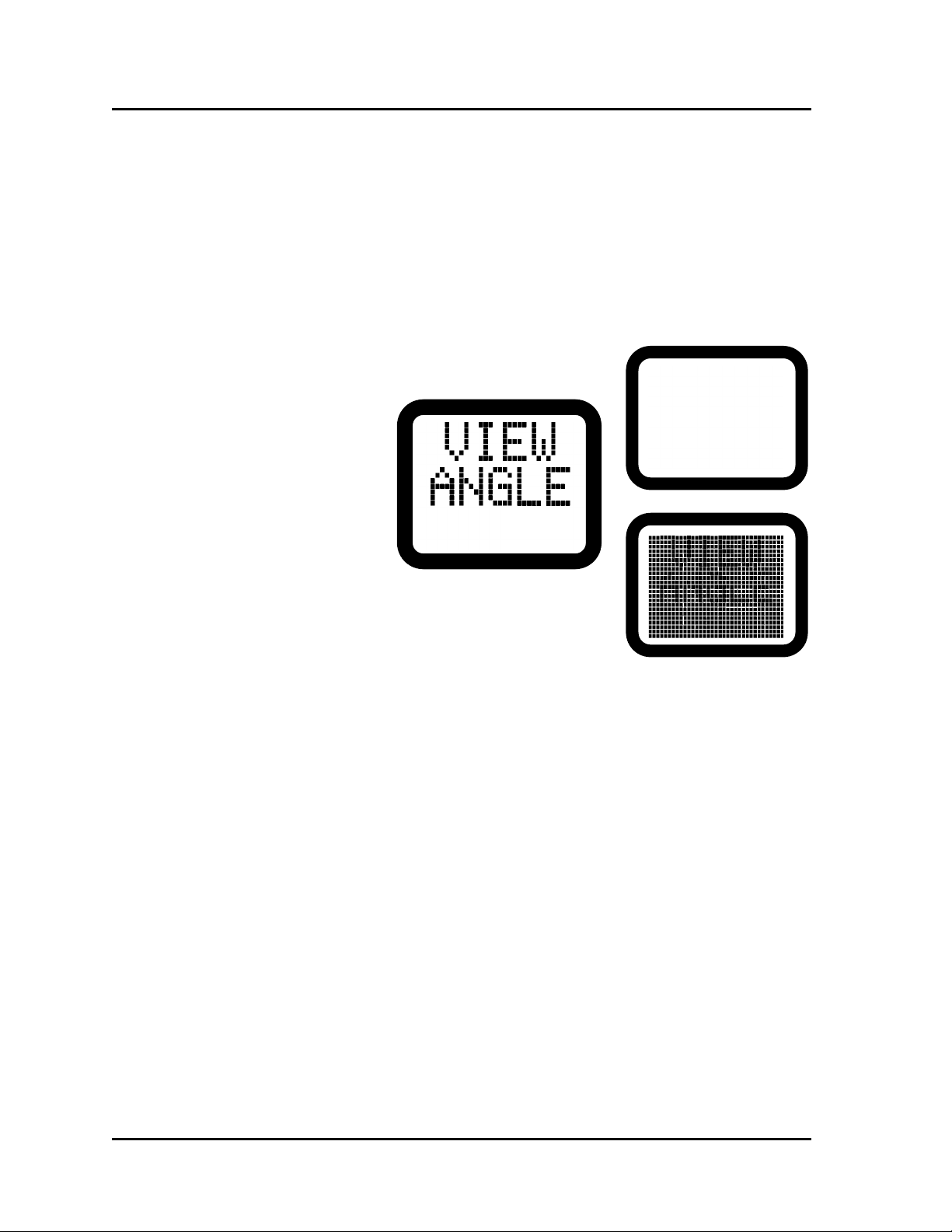
VIEW ANGLE
Although this screen is actually considered a secondary screen, accessed by pressing and
holding the display for more than one second, it is discussed first because the possibility
exists that if the instrument is in an extreme-temperature environment, the screen will not
be visible when the unit is energized. It may be black or it may be blank. If this occurs,
press and hold the display for more than one second, and then rotate (counterclockwise if
too dark, and clockwise if too light) the encoder (round knob) until the words VIEW ANGLE
are visible.
At this point, the user can either wait approximately twenty seconds (or press the display
twice or press and hold the display for more than one second) to return to the operate screen.
CONTROLLING THE MODEL 441A
The controls on the front panel consist of a display, which has the additional function of
screen selection, and the encoder, which has the dual function of character selection and
control. Using these two controls is all that is necessary to fully operate the Model 441A.
Display As stated above, the display has the dual function of
display and screen selection. There are two ways to
select a screen. One is to press and release. This selects
Figure 3-2
View Angle
Normal and extreme
view angles
Operation Model 441A
3-4
Table of contents


