manuals.online logo
Brands
  1. Home
  2. •
  3. Brands
  4. •
  5. Danfoss
  6. •
  7. Media Converter
  8. •
  9. Danfoss FCM 300 PROFIBUS User manual

Danfoss FCM 300 PROFIBUS User manual

FCM 300 PROFIBUS / VLT 2800 PROFIBUS
MG.90.A2.02 – VLT is a registered Danfoss trademark 1
Contents
■Introduction ..............................................................3
■Quick Setup..............................................................4
■The PROFIBUS interface .......................................... 5
■FCM 300FCM 300
FCM 300FCM 300
FCM 300 - Physical connection ............................... 7
■VLVL
VLVL
VLT 2800T 2800
T 2800T 2800
T 2800 - Physical connection............................. 10
■System layout ......................................................... 13
■Timing .................................................................... 15
■DP (Distributed Periphery)....................................... 16
■Parameters............................................................. 30
■Warning and alarm messages ................................35
■Glossary and parameter list.................................... 36
■Index ......................................................................39
Copyrights, Limitation of Liability and Revision Rights.
This publication contains information proprietary to Danfoss A/S. By accepting and using this manual the user
agrees that the information contained herein will be used solely for operating equipment of Danfoss A/S or
equipment from other vendors provided that such equipment is intended for communication with Danfoss
equipment over a PROFIBUS serial communication link. This publication is protected under the Copyright laws of
Denmark and most other countries.
Danfoss A/S does not warrant that a software program produced according to the guidelines provided in this
manual will function properly in every physical, hardware or software environment.
Although Danfoss A/S has tested and reviewed the documentation within this manual, Danfoss A/S makes no
warranty or representation, either express or implied, with respect to this documentation, including its quality,
performance, or fitness for a particular purpose.
In no event shall Danfoss A/S be liable for direct, indirect, special, incidental, or consequential damages arising
out of the use, or the inability to use information contained in this manual, even if advised of the possibility of such
damages. In particular, Danfoss A/S is not responsible for any costs including but not limited to those incurred as
a result of lost profits or revenue, loss or damage of equipment, loss of computer programs, loss of data, the
costs to substitute these, or any claims by third parties.
Danfoss A/S reserves the right to revise this publication at any time and to make changes in its contents without
prior notice or any obligation to notify previous users of such revisions or changes.
MG.90.A2.02 – VLT is a registered Danfoss trademark
2
FCM 300 PROFIBUS / VLT 2800 PROFIBUS
When reading through this manual, you will come
across various symbols that require special attention.
The symbols used are the following:
Indicates a general warning.
Indicates something to be noted by
the reader.
Indicates a high-voltage warning.
PROFIBUS is a registered trademark.
FCM 300 PROFIBUS / VLT 2800 PROFIBUS
MG.90.A2.02 – VLT is a registered Danfoss trademark 3
■About this manual
This manual is intended to be used both as an
instructional and as a reference manual. It only briefly
touches on the basics of the PROFIBUS protocol
whenever it is necessary for gaining an understanding
of the PROFIDRIVE implementation of the PROFIBUS
Profile for Variable Speed Drives (VDI/VDE 3689) and
the DANFOSS PROFIBUS for the FC motor and the
VLT 2800.
The manual is also intended to serve as a guideline
when you specify and optimize your communication
system.
If you are not completely familiar with PROFIBUS or
the Profile for Variable Speed Drives, it may be
advisable to read some of the material provided on
these subjects, eg DIN 19245 parts 1 and 3 and VDI/
VDE 3689.
Even if you are an experienced PROFIBUS
programmer, we suggest that you read this manual in
its entirety before you start programming, since
important information can be found in all chapters.
■Assumptions
This manual assumes that you are using a DANFOSS
FCM 300 and VLT 2800 with PROFIBUS. It is also
assumed that you, as a master, are using a PLC or
PC that is equipped with a serial communication card
supporting all the PROFIBUS communication services
required by your application, and that all
requirements stipulated in the PROFIBUS standard as
well as those set up in the PROFIBUS Variable Speed
Drives Profile and its company-specific
implementation PROFIDRIVE, as well as those
pertaining to the VLT Variable Speed Drive are strictly
observed as well as all limitations therein fully
respected.
■What you should already know
The DANFOSS PROFIBUS is designed to
communicate with any master abiding by the
PROFIBUS DP standard. It is therefore assumed that
you have full knowledge of the PC or PLC you intend
to use as a master in your system. Any questions
pertaining to hardware or software produced by any
other manufacturer is beyond the scope of this
manual and is of no concern to DANFOSS.
If you have questions about how to set up master -
master communication or communication to a non-
Danfoss slave, the appropriate manuals should be
consulted.
Introduction
MG.90.A2.02 – VLT is a registered Danfoss trademark
4
FCM 300 PROFIBUS / VLT 2800 PROFIBUS
Programming: See the design guide:
FC motor (MG.03.Bx.02)
VLT 2800 (MG.28.Ex.02)
for descriptions on how to programme the ordinary
FC motor and VLT 2800.
Communication is established by setting the
parameters stated below.
Setting up the master: See the manual on the master
as well as the chapters of this manual giving details
on the PROFIBUS interface for information on how to
set up the master.
Quick Setup
■General information
Parameter 918:
Set the station address, - one unique address per
unit.
In parameters 502-508 it is possible to define how to
gate the control commands from the PROFIBUS with
the equivalent control commands of the digital inputs.
The FC motor/VLT 2800 adjusts to the baudrate and
the configuration from the master.
FCM 300 PROFIBUS / VLT 2800 PROFIBUS
MG.90.A2.02 – VLT is a registered Danfoss trademark 5
The PROFIBUS Interface
■Master controlled Variable Speed Drives (VSD)
The PROFIBUS Field-bus was designed to give you
unprecedented flexibility and command over your
VSD controlled system. The PROFIBUS will perform
as an integrated part of your VLT VSD, giving you
access to all parameters relevant to your application.
The VSD will always act as a slave, and together with
a master it can exchange a multitude of information
and commands. Control signals such as speed
reference, start / stop of motor, reverse operation,
etc. are transmitted from the master in the form of a
telegramme. The VSD acknowledges receipt by
transmitting status signals, such as running, on
reference, motor stopped and so on to the master.
The VSD may also transmit fault indications, alarms
and warnings to the master, such as Overcurrent or
Phaseloss.
The PROFIBUS communicates according to the
PROFIBUS Protocol Standard DIN 19245 parts 1 and
3. This means that it can communicate with all
masters that comply with this standard, but it does
not necessarily mean that all services available in the
PROFIBUS standard are supported. The VDI / VDE
3689 PROFIBUS Profile for Variable Speed Drives is a
subset of PROFIBUS which only supports the
services relevant to speed control applications.
PROFIDRIVE is an implementation of VDI / VDE 3689
profile created by DANFOSS and a number of other
companies.
Communication partners
In a control system the VSD will always act as a slave,
and as such it may communicate with a single master
or multiple masters depending on the nature of the
application. A master may be a PLC or a PC that is
equipped with a PROFIBUS communication card.
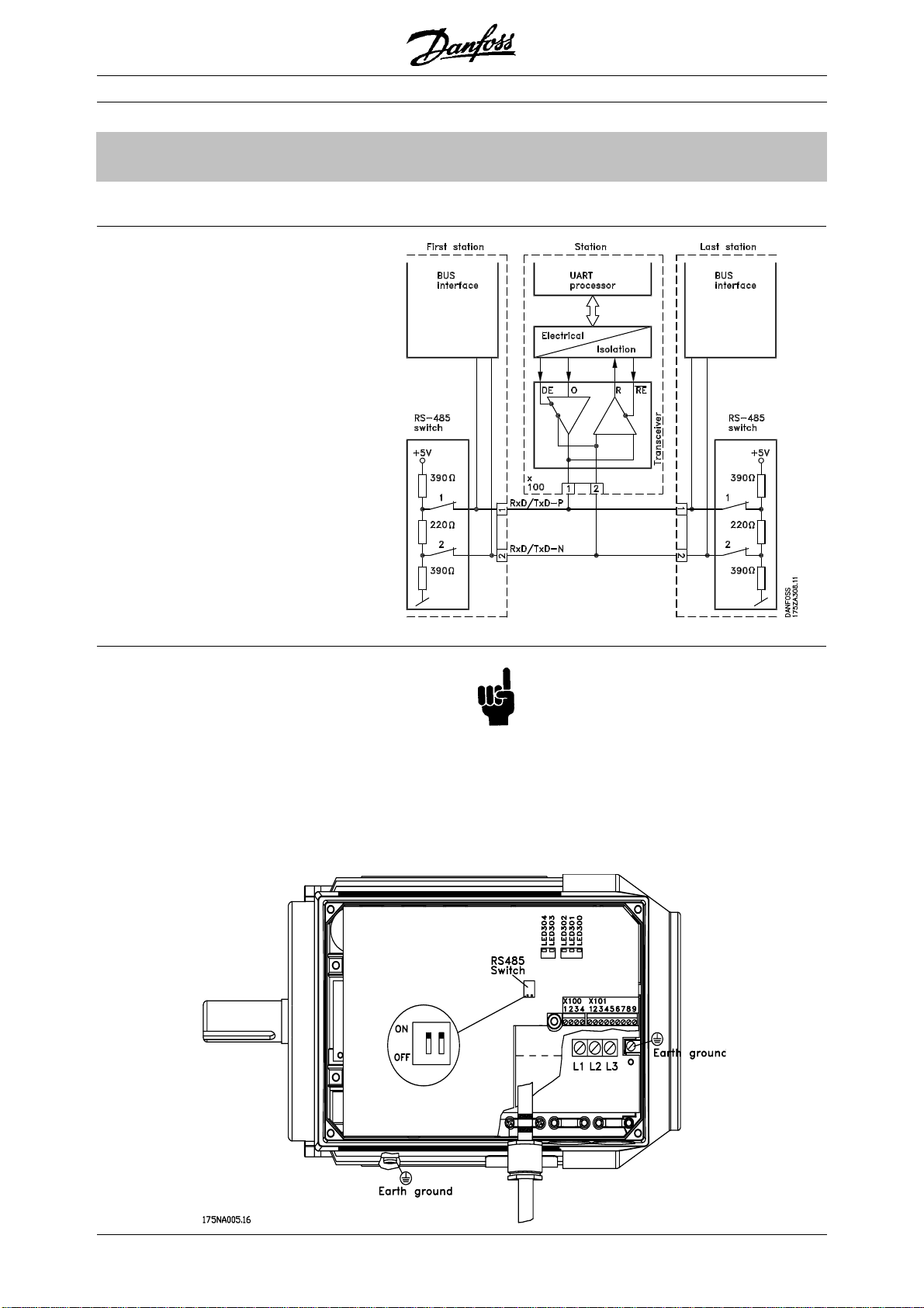
■Physical layer
The field of application of a field-bus system is
primarily determined by the transmission media and
the physical bus interface selected. The type of bus
cable required for the application and its installation
(physical layer) are particularly important factors, in
addition to the required transmission reliability of the
physical level.
Though a fundamental feature of the PROFIBUS stan-
dard is the possibility of specifying several different
physical interfaces, the standard, at the time of
printing, has allowed for one universal specification
only, namely the EIA Standard RS 485-A, which has
found acceptance both in the field of factory automa-
tion and in several areas of the processing industry.
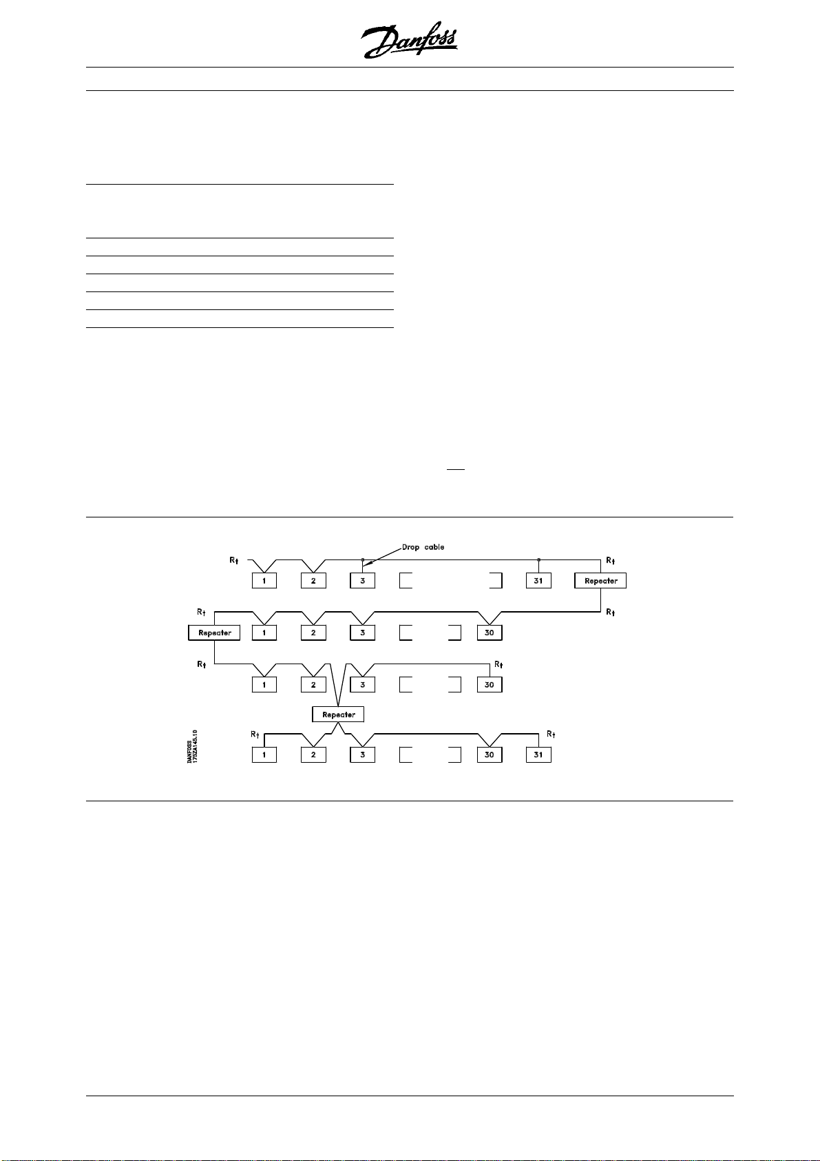
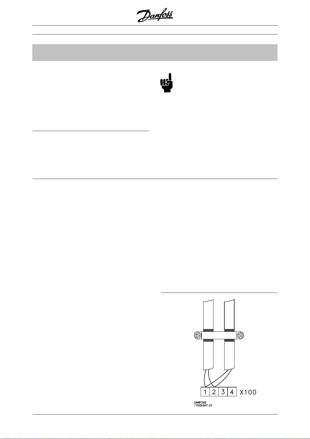
■Cable lengths/number of nodes
The maximum cable length in one segment is
depending on the transmission speed. The total cable
length includes drop cables if any. A drop cable is the
connection from the main bus cable to each node if a
T-connection is used instead of connecting the main
bus cable directly to the nodes, see drop cable
length. The table below shows the maximum allowed
cable length and maximum number of nodes/VLT’s
with 1, 2, 3 and 4 bus segments.
Note that a repeater is a node in both of the two
segments it connects. The number of VLT is based on
a single master system. If there are more masters the
number of VLT must be reduced correspondingly.
Max. total bus cable lenght
1 segment: 2 segments: 3 segments: 4 segments:
32 nodes 64 nodes 96 nodes 128 nodes
Transmission (31 VLT) (1 repeater, 61 VLT) (2 repeaters, 91 VLT) (3 repeaters, 121 VLT)
speed [m] [m] [m] [m]
9.6-187.5 kBaud 1000 2000 3000 4000
500 kBaud 400 800 1200 1600
1.5 MBaud 200 400 600 800
3MBaud 100 200 300 400
MG.90.A2.02 – VLT is a registered Danfoss trademark
6
FCM 300 PROFIBUS / VLT 2800 PROFIBUS
The total drop cable length for one segment is limited
as stated in the table below.
Drop cable length Max. drop cable
length per segment
Transmission speed [m]
9.6-93.75 kBaud 96
187.5 kBaud 75
500 kBaud 30
1.5 MBaud 10
3MBaud none
The length statements in the tables above are valid
provided that bus cable with the following properties
is used:
- Impedance: 135 to 165 ohm
at a measuring frequency from 3 to
20 MHz
- Resistance: <110 ohm/km
- Capacity: <30 pF/m
- Damping: max. 9 dB over the whole wire
length
- Cross section: max. 0.34 mm2,
corresponding to AWG 22
- Cable type: twisted in pairs,
1 x 2, or 2 x 2, or 1 x 4 wires
- Screening: Copper-braided screen
or braided screen and foil screen
It is recommended to use the same cable type in the
entire network to avoid impedance mismatch.
The numbers on the following drawing indicate the
maximum number of stations in each segment. They
are not the station addresses as each station in the
network must have a unique address.
The PROFIBUS Interface
Segment 3
Segment 1
Segment 2
Segment 4
Rt = termination
resistors
FCM 300 PROFIBUS / VLT 2800 PROFIBUS
MG.90.A2.02 – VLT is a registered Danfoss trademark 7
Relevant national and local regulations, for
example regarding protective earth
connection, must be observed.
- Cable routing
The PROFIBUS communication cable must be
kept away from motor and brake resistor cables to
avoid coupling of high frequency noise from one
cable to the other. Normally a distance of 200 mm
is sufficient, but it is generally recommended to
keep the greatest possible distance between the
cables, especially where cables are running in
parallel over long distances.
■Physical connection
The PROFIBUS is connected to the bus line via X100,
terminals 1 and 2.
It is recommended to use a master with a galvanic
isolated bus driver and with over voltage protection
(e.g. zenerdiode).
EMC precautions
The following EMC precautions are recommended to
obtain interference free operation of the PROFIBUS
network. Additional information on EMC can be found
in the design guide on the FC motor (MG.03.Bx.02).
Please also consult the manual of the PROFIBUS
master for further installation guidelines.
FCM 300:FCM 300:
FCM 300:FCM 300:
FCM 300:
If the PROFIBUS cable has to cross a motor and
brake resistor cable they must cross each other at
an angle of 90°.
- Connection of the cable screen
The screen of the PROFIBUS cable must always
be connected to ground at both ends, that means
the screen must be connected to ground in all
stations connected to the PROFIBUS network. It
is very important to have a low impedance
ground connection of the screen, also at high
frequencies.This can be obtained by connecting
the surface of the screen to ground, for example
by means of a cable clamp or a conductive cable
gland.
The FC motor Series is provided with different
clamps and brackets to enable a proper ground
connection of the PROFIBUS cable screen. The
screen connection is shown in the following
drawing.
- Earth connection
It is important that all stations connected to the
PROFIBUS network are connected to the same
earth potential. The earth connection must have a
low HF (high frequency) impedance. This can be
achieved by connecting a large surface area of the
cabinet to earth, for example by mounting the FC
motor on a conductive rear plate.
Especially when having long distances between
the stations in a PROFIBUS network it can be
necessary to use additional potential equalizing
cables, connecting the individual stations to the
same earth potential.
Connecting the bus line
The PROFIBUS Interface
MG.90.A2.02 – VLT is a registered Danfoss trademark
8
FCM 300 PROFIBUS / VLT 2800 PROFIBUS
The bus termination
See drawing on page 6
The PROFIBUS Interface
It is essential that the bus line be terminated properly.
A mismatch of impedance may result in reflections
on the line that will corrupt data transmission.
- The PROFIBUS is provided with a suitable
termination which may be activated by the
switches of the RS485 switch block located
just to the left of the terminal block X100 (see
drawing below). The switches should be on to
terminate the bus.
The switches should never be left in opposite
positions. They should either both be ON or
both be OFF!
- Most masters and repeaters are equipped with
their own termination.
- If an external termination circuit consisting of three
resistors is connected to the bus line a 5 V d.c.
power supply must be used, please note that this
must be galvanically isolated from the a.c. line.
FCM 300:FCM 300:
FCM 300:FCM 300:
FCM 300:
FCM 300 PROFIBUS / VLT 2800 PROFIBUS
MG.90.A2.02 – VLT is a registered Danfoss trademark 9
■LEDs
There are 2 LEDs on the PROFIBUS:
LED303: Lights up when the card is initialized
and ready to communicate. It will
flash while auto baudrate detection is
attempting to detect the actual
baudrate.
LED304: Lights up when the card is
communicating, depending on
baudrate.
A high baudrate results in dim light in LED304.
The PROFIBUS Interface
FCM 300:FCM 300:
FCM 300:FCM 300:
FCM 300:
MG.90.A2.02 – VLT is a registered Danfoss trademark
10
FCM 300 PROFIBUS / VLT 2800 PROFIBUS
Relevant national and local regulations, for
example regarding protective earth
connection, must be observed.
- Cable routing
The PROFIBUS communication cable must be
kept away from motor and brake resistor cables to
avoid coupling of high frequency noise from one
cable to the other. Normally a distance of 200 mm
is sufficient, but it is generally recommended to
keep the greatest possible distance between the
cables, especially where cables are running in
parallel over long distances.
■Physical connection
The PROFIBUS is connected to the bus line via,
terminals 68 and 69.
It is recommended to use a master with a galvanic
isolated bus driver and with over voltage protection
(e.g. zenerdiode).
EMC precautions
The following EMC precautions are recommended to
obtain interference free operation of the PROFIBUS
network. Additional information on EMC can be found
in the design guide on the VLT 2800 (MG.28.Ex.02).
Please also consult the manual of the PROFIBUS
master for further installation guidelines.
VLVL
VLVL
VLT 2800T 2800
T 2800T 2800
T 2800::
::
:
If the PROFIBUS cable has to cross a motor and
brake resistor cable they must cross each other at
an angle of 90°.
- Connection of the cable screen
The screen of the PROFIBUS cable must always
be connected to ground at both ends, that means
the screen must be connected to ground in all
stations connected to the PROFIBUS network. It
is very important to have a low impedance
ground connection of the screen, also at high
frequencies.This can be obtained by connecting
the surface of the screen to ground, for example
by means of a cable clamp or a conductive cable
gland.
The VLT 2800 Series is provided with different
clamps and brackets to enable a proper ground
connection of the PROFIBUS cable screen. The
screen connection is shown in the following
drawing.
- Earth connection
It is important that all stations connected to the
PROFIBUS network are connected to the same
earth potential. The earth connection must have a
low HF (high frequency) impedance. This can be
achieved by connecting a large surface area of the
cabinet to earth, for example by mounting the VLT
2800 on a conductive rear plate.
Especially when having long distances between
the stations in a PROFIBUS network it can be
necessary to use additional potential equalizing
cables, connecting the individual stations to the
same earth potential.
Connecting the bus line
The PROFIBUS Interface
FCM 300 PROFIBUS / VLT 2800 PROFIBUS
MG.90.A2.02 – VLT is a registered Danfoss trademark 11
The bus termination
See drawing on page 6
The PROFIBUS Interface
It is essential that the bus line be terminated properly.
A mismatch of impedance may result in reflections on
the line that will corrupt data transmission.
- The PROFIBUS is provided with a suitable
termination which may be activated by the
switches of the RS485 switch block located
just to the left of the terminal block X100 (see
drawing below). The switches should be on to
terminate the bus.
The switches should never be left in opposite
positions. They should either both be ON or
both be OFF!
- Most masters and repeaters are equipped with
their own termination.
- If an external termination circuit consisting of three
resistors is connected to the bus line a 5 V d.c.
power supply must be used, please note that this
must be galvanically isolated from the a.c. line.
VLVL
VLVL
VLT 2800T 2800
T 2800T 2800
T 2800::
::
:
MG.90.A2.02 – VLT is a registered Danfoss trademark
12
FCM 300 PROFIBUS / VLT 2800 PROFIBUS
■LEDs
There are 2 LEDs on the PROFIBUS:
LD851: Lights up when the card is initialized
and ready to communicate. It will
flash while auto baudrate detection is
attempting to detect the actual
baudrate.
LD852: Lights up when the card is
communicating, depending on
baudrate.
A high baudrate results in dim light in LD852.
VLVL
VLVL
VLT 2800T 2800
T 2800T 2800
T 2800::
::
:
The PROFIBUS Interface
FCM 300 PROFIBUS / VLT 2800 PROFIBUS
MG.90.A2.02 – VLT is a registered Danfoss trademark 13
System layout
■Bus topology
Single master operation with DP
- Single master
- PLC communicates with telegrams of constant
length
- Fits to time critical requirements
- No need for equidistant transmissions of
set points
Cyclical transmission
1. Set point transmission
2. Actual value feed back
3. New setpoints computed
4. New setpoint transfer
FeaturFeatur
FeaturFeatur
Features of DPes of DP
es of DPes of DP
es of DP (Distributed Periphery)
- Is used by several PLC manufacturers for remote
peripheral I/O communication.
- Supports cyclical communication.
- SRD service gives fast cyclical exchange of
process data between master and slaves.
- Freeze and synchronize function is supported
- Fixed data structure.
- Fixed telegramme size.
- Occupies I/O memory space in PLC proportional
to the number of slaves employed, which may limit
the number of participants. Additional data
require additional I/O memory space.
Transferring large amount of data where rapid transfer
of process data does not have highest priority
DP should be used when fast cyclical process control
is needed. Such a concept would typically call for
single master operation with a limited number of slave
stations. (A high number of slaves will reduce the
system response).
This could also be the case where control loops are
closed over the bus.
As a very fast alternative it is of course possible to
close the control loop outside the bus.
MG.90.A2.02 – VLT is a registered Danfoss trademark
14
FCM 300 PROFIBUS / VLT 2800 PROFIBUS
Closing the control loop over the bus Closing the control loop outside the fieldbus
for extremely fast feed-back
Rapid Cyclical transmission with PPO using DP
System layout
Parameter up-/downloads can be achieved by using
the so-called Parameter / Process Objects - PPOs -
of 12, 20 or 28 bytes length as specified in the VDI/
VDE 3689 profile, see drawing page 16.
This procedure, however, occupies 8 bytes additional
I/O memory space in the PLC bytes per slave, and
slows down the system (see also “Timing” page 15).
Control of the drives during normal operation is often
very time critical, but it involves very few data, such
as control commands and speed reference. DP is
optimized for fast cyclical communication.
■Features and services supported by FC motor
and the VLT 2800
Features available as described by the unit
classification
The unit classification as layed out in the PROFIBUS
Profile for VSDs describes the functionality of the unit.
There are 4 classes where class 1 signifies the lowest
performance class, and class 4 the highest.
The FC motor / VLT 2800 is a class 3 unit except for
the following features:
- Fault buffer
- Change access rights for parameter write
- Change access rights for process control
- Time difference
- Hardware configuration ident.
The FC motor / VLT 2800 complies with the following
class 4 features:
- Baudrate > 500 kBaud
- Programmable content of PCD 3 through 6 (10) of
the PPO’s
- PPO type 5
FCM 300 PROFIBUS / VLT 2800 PROFIBUS
MG.90.A2.02 – VLT is a registered Danfoss trademark 15
■■
■■
■FC motor / VLT 2800 response time
The update time via the PROFIBUS connection can
be divided in two parts:
1) The communication time, which is the time it takes
to transmit data from the master to the slave (FC
motor / VLT 2800 with PROFIBUS), and 2) the
internal update time, which is the time it takes to
transmit data between the FC motor / VLT 2800
control card and the PROFIBUS.
Timing
■■
■■
■System update time
The system update time is the time it takes to
update all the slaves in the network when using
cyclical communication. The drawing below shows
the value which is obtainable in theory at 2 input
and 2 output bytes.
Communication time (tcom) depends on the actual
transmission speed (baudrate) and the type of master
in use. The minimum obtainable communication time
with the FC motor / VLT 2800 with PROFIBUS is
approx. 100 µsec per slave, when using DP
communication with 4 bytes of data (PPO type 3) at 3
Mbaud. More data or lower transmission speed will
increase the communication time.
The internal update time (tint) depends on the type of
data in question as there are different channels for the
data transfer where time critical data e.g. control
word has highest priority. The internal update time for
the different types of data are stated below.
Update
Data time, tint
Control word/Main reference
(part of PPO) 42 msec
Status word/Actual output frequency
(part of PPO) 40 msec
Parameter read (PCD 1-8) 40 msec
Parameter write (PCD 1-2) 160 msec
Parameter write (PCD 3-4) 320 msec
Parameter write (PCD 5-8) 640 msec
Parameter read (PCV) 41 msec
Parameter write (PCV) 40 msec
MG.90.A2.02 – VLT is a registered Danfoss trademark
16
FCM 300 PROFIBUS / VLT 2800 PROFIBUS
PPO. Parameter-Process Data Object
By DP one of the following shown PPO’s must be used:
PCD: Process Data
PCV: Parameter-Characteristics-Value
PCA: Parameter-Characteristics (Bytes 1, 2)
PCA handling below
IND: Subindex (Byte 3), (Byte 4 is not used)
PVA: Parameter value (Bytes 5 to 8)
CTW: Control word see page 22
STW: Status word
MRV: Main reference value
MAV: Main actual value (Actual output frequency)
■DP communication relations
Communication according to PROFIBUS DP, i.e. DIN
19245 part 1 & 3, is supported. Consequently a
master that supports PROFIBUS DP must be used.
■PPO description
A special feature of the PROFIBUS Profile for VSD’s is
the communication object called a PPO, meaning
Parameter-Process Data Object.
The PPO is well suited for fast cyclical data transfer,
and may, as the name implies, carry both process
data and parameters.
The selection of PPO type is made according to the
master request.
A PPO may consist of a parameter part and process
data part. The parameter part can be used for
reading and/or updating the parameters one by one.
DP
The process data part consists of a fixed part (4
bytes) and a parametrable part (8 or 16 bytes). In the
fixed part control word and speed reference are
transfered to the VLT while status word and actual
output frequency feedback are transfered from the
VLT. In the parametrable part the user chooses which
parameters have to be transfered to (parameter 915)
and which from (parameter 916) the VLT.
Type 1, 2 and 5 consist of the parameter part and 4,
12 and 20 byte process data, respectively.
Type 3 and 4 consist of 4 and 12 byte process data,
respectively.
By DP communication one of the parameter-process
data objects (PPO’s) described below must be used.
FCM 300 PROFIBUS / VLT 2800 PROFIBUS
MG.90.A2.02 – VLT is a registered Danfoss trademark 17
DP
■PCA handling
The PCA portion of the PPO types 1, 2 and 5 will
handle a number of tasks. The master may control
and supervise parameters and request a response
from the slave, while the slave, apart from responding
to a request from the master may transmit a
spontaneous message.
Requests and responses is a handshake procedure
and cannot be batched, meaning that if the master
sends out a Read/write request, it has to wait for the
response, before it sends a new request. The request
or response data value will be limited to max. 4 bytes,
which implies that text strings are not transferable.
PCA - Parameter Characteristics
RC content
Request Function
0 No request
1 Request parameter value
2 Change parameter value (word)
3 Change parameter value (long word)
4 Request description element
5 Change description element
6 Request parameter value (array)
7 Change parameter value (array word)
8
Change parameter value (array long word)
9 Request number of array elements
10-15 Not used
Request/response handling
The RC portion of the PCA word defines the requests
that may be issued from the master to the slave as
well as what other portions of the PCV (IND and PVA)
are involved.
The PVA portion will transmit word-size parameter
values in bytes 7 and 8, while long word size values
require bytes 5 to 8 (32 bits).
If the Response / Request contains array elements,
the IND will carry the Array Subindex. If parameter
descriptions are involved, the IND will hold the Record
Subindex of the Parameter description.
Response Function
0 No response
1 Transfer parameter value (word)
2 Transfer parameter value (long word)
3 Transfer description element
4 Transfer parameter value (array word)
5
Transfer parameter value (array long word)
6 Transfer number of array elements
7 Request rejected (incl. fault #, see below)
8 Not seviceable by PCV interface
9 Spontaneous message (word)
10 Spontaneous message (long word)
11 Spontaneous message (array word)
12 Spontaneous message (array long word)
13-15 Not used
If the slave rejects a request from the master, the RC word in
the PPO-read will indicate this by assuming the value 7.
The fault # will be carried by bytes 7 and 8 in the PVA element.
Fault # Interpretation
0 Illegal PNU
1 Parameter value cannot be changed
2 Upper or lower limit exceeded
3 Subindex corrupted
4 No array
5 Data type false
6 Cannot be set by user (reset only)
7 Description element cannot be changed
8 IR required PPO-write not available
9 Description data not available
10 Access group
11 No parameter write access
12 Key word missing
13
Text in cyclical transmission not readable
14
Name in cyclical transmission not readable
15 Text array not available
16 PPO-write missing
17 Request temporarily rejected
18 Other fault
19
Date in cyclical transmission not readable
130 There is no bus access to the parameter
called
131 Data change is not possible because
factory Setup has been selected
RC: Request/respons Characteristics (Range: 0..15)
SPM: Toggle-Bit for Spontaneous Messages
PNU: Parameter # (Range: 1..1999)
15141312 11 109876543210
RC SMP PNU
MG.90.A2.02 – VLT is a registered Danfoss trademark
18
FCM 300 PROFIBUS / VLT 2800 PROFIBUS
DP
■Parameter and data type structure description
Parameter description:
DP has a number of describing attributes (see rigth).
Read/write on parameter description is made by the
PCV part using the RC commands 4/5 and subindex
of the desired description element.
Size attribute
The size index and the conversion index for each
parameter can be taken from the parameter list on
page 36.
Physical unit Size index Measuring unit Designation Conversion index Conversion factor
0 No dimension 0 1
second s 0 1
-1 0.1
-2 0.01
Time 4 millisecond ms -3 0.001
minute min 70 60
hour h 74 3600
day d 77 86400
watthour Wh 0 1
Energy 8 kilowatthour kWh 3 1000
megawatthour MWh 6 106
milliwatt mW -3 0.001
watt W 0 1
Power 9 kilowatt kW 3 1000
megawatt MW 6 106
Rotation 11 rotation per minute RPM 0 1
Torque 16 newtonmeter Nm 0 1
kilonewtonmeter kNm 3 1000
Temperature 17 degree Celsius °C 0 1
millivolt mV -3 0.001
Voltage 21 volt V 0 1
kilovolt kV 3 1000
milliampere mA -3 0.001
Current 22 ampere A 0 1
kiloampere kA 3 1000
milliohm mOhm -3 0.001
Resistance 23 ohm Ohm 0 1
kiloohm kOhm 3 1000
Ratio 24 per cent % 0 1
Relative change 27 per cent % 0 1
hertz Hz 0 1
Frequency 28 kilohertz kHz 3 1000
megahertz MHz 6 106
gigahertz GHz 9 109
PNU Characteristics
Subindex 1
Size of elements
Subindex 2
Size attributes
Subindex 4
Lower limit
Subindex 7
Upper limit
Subindex 8
Extended characteristics
Subindex 10
FCM 300 PROFIBUS / VLT 2800 PROFIBUS
MG.90.A2.02 – VLT is a registered Danfoss trademark 19
■Object and data types supported by FC motor
and VLT 2800
Data types supported by FC motor and VLT 2800
Data Object Short Description
type Code name
3 5 12 Integer 16
5 5 Unsigned 8
6 5 O2 Unsigned 16
7 5 O4 Unsigned 32
10 5 Byte string
13 5 Time difference1)
33 5 N2 Standardized value (16 bit) 1)
35 5 V2 Bit sequence 1)
1) See elaboration below
Time difference
The data type time difference is a time indication in
milliseconds.
Notation: Time difference
Value range: 0 ≤i ≤ (232 -1) milliseconds
Coding: The time is presented as a binary
value of 32 bits (4 bytes). The first
four (MSB) bits are always zero.
Time difference is thus a byte string
of 4 bytes.
Data coding of the data type time difference
Bit Byte 1 Byte 2 Byte 3 Byte 4
80ms2
23 ms 215 ms 27ms MSB
70ms2
22 ms 214 ms 26ms MSB
60ms2
21 ms 213 ms 25ms MSB
50ms2
20 ms 212 ms 24ms MSB
42
27 ms 219 ms 211 ms 23ms
32
26 ms 218 ms 210 ms 22ms
22
25 ms 217 ms 29ms 21ms
12
24 ms 216 ms 28ms 20ms
Standardized value
A liniary value.
0% = 0 (0h), 100% is 214 (4000h)
Data type N 2
Range -200% ... 200% – 2 –14
Resolution 2 –14 = 0.0061%
Length 2 bytes
Notation: 2’s complement notation.
MSB is 1st bit after sign bit in 1st byte.
Sign bit = 0 = positive number
Sign bit = 1 = negative number
Bit 8 7 6 5 4 3 2 1
Byte 1 SIGN 202–1 2–2 2–3 2–4 2–5 2–6
Byte 2 2–7 2–8 2–9 2–10 2–11 2–12 2–13 2–14
Bit sequence
16 boolean values for control and presentation of user
functions. Notation is binary.
Bit 87654321
Byte 1 15 14 13 12 11 10 9 8
Byte 2 7 6 5 4 3 2 1 0
■Spontaneous messages
The Spontaneous message is activated by the active
parameters i.e. 538, 540, or 953 and will be carried
with the PCV response, stating PNU and PVA of the
changed active parameter that triggered the
message.
Spontaneous messages are generated when the
value is changed in one of the abovementioned
parameters. It means that a message will be sent
when a warning comes, and when a warning
disappears.
Simultaneously the VLT will toggle the SPM bit (11) of
PCA word (see “PCA handling” page 17).
The Spontaneous messages will be transmitted until
the master has acknowledged reception of the
message by changing the SPM bit.
Spontaneous messages are only active when
parameter 917 is “ON”!
DP
MG.90.A2.02 – VLT is a registered Danfoss trademark
20
FCM 300 PROFIBUS / VLT 2800 PROFIBUS
DP
Example of SPM execution
In the VLT the SPMs are temporarily stored in a FIFO
buffer. This means that up to 16 consecutive SPMs
can be retained. If only one SPM has entered the
FIFO, the VLT will resume normal communication as
soon as the SPM has been acknowledged by the
master (and the condition causing the SPM been
rectified). If more SPMs are in the FIFO, these will be
transmitted consecutively upon acknowledgement. If
more SPMs are triggered when the FIFO is full, these
will be ignored.
■Synchronize and freeze
The control commands SYNC/UNSYNC and
FREEZE/UNFREEZE are broadcast functions. SYNC/
UNSYNC is used to send syncronized control
commands and/or speed reference to all the
connected slaves (FC motor Series/VLT 2800 Series).
FREEZE/UNFREEZE is used to freeze the status
feedback in the slaves to get syncronized feedback
from all connected slaves.
The synchronize and freeze commands only affect
Process Data (the PCD part of the PPO).
SYNC/UNSYNC
SYNC/UNSYNC can be used to obtain simultaneous
reactions in several slaves, for example synchronised
start, stop or speed change. A SYNC command will
freeze the actual control word and speed reference,
incoming Process Data will be stored but not used
until a new SYNC command or a UNSYNC command
is received.
See the example below where the left column holds
the speed reference send out by the master and the
three right columns hold the actual speed reference
used in each of the three slaves.
Actual slave speed reference
VLT VLT VLT
From DP master to address: Address 3 Address 4 Address 5
1. Speed reference = 50 % to address 3 ⇒50 % 0 % 0 %
2. Speed reference = 50 % to address 4 50 % ⇒50 % 0 %
3. Speed reference = 50 % to address 5 50 % 50 % ⇒50 %
4. SYNC command to all addresses ⇒50 % ⇒50 % ⇒50 %
5. Speed reference = 75 % to address 3 ⇒50 % 50 % 50 %
6. Speed reference = 75 % to address 4 50 % ⇒50 % 50 %
7. Speed reference = 75 % to address 5 50 % 50 % ⇒50 %
8. SYNC command to all addresses ⇒75 % ⇒75 % ⇒75 %
9. Speed reference = 100 % to address 3 ⇒75 % 75 % 75 %
10. Speed reference = 50 % to address 4 75 % ⇒75 % 75 %
11. Speed reference = 25 % to address 5 75 % 75 % ⇒75 %
12. UNSYNC command to all addresses ⇒100 % ⇒50 % ⇒25 %
13. Speed reference = 0 % to address 3 ⇒0% 50% 25%
14. Speed reference = 0 % to address 4 0 % ⇒0% 25%
15. Speed reference = 0 % to address 5 0 % 0 % ⇒0%
MASTER
SPM 2 NOT ACK.
REQ 1
REQ 2
SPM 1 ACK.
REQ 2
SPM 2 ACK.
SLAVE
RES. 1
SPM 1
SPM 2
SPM 2
RES. 2
0
0
0
0
0
0
0
1
1
1
PCA
SPM BIT

This manual suits for next models

2

Other Danfoss Media Converter manuals

Danfoss Compressor Drive CD302 User manual

Danfoss

Danfoss Compressor Drive CD302 User manual

Danfoss VLT 2800 Series User manual

Danfoss

Danfoss VLT 2800 Series User manual

Danfoss D9h User manual

Danfoss

Danfoss D9h User manual

Danfoss VLT PROFIBUS DP MCA 101 User manual

Danfoss

Danfoss VLT PROFIBUS DP MCA 101 User manual

Danfoss iC7 Series User manual

Danfoss

Danfoss iC7 Series User manual

Danfoss HJM022D20Q User manual

Danfoss

Danfoss HJM022D20Q User manual

Danfoss VLT 5000 Installation and operating instructions

Danfoss

Danfoss VLT 5000 Installation and operating instructions

Danfoss iC7 Series User manual

Danfoss

Danfoss iC7 Series User manual

Danfoss VLT HVAC Drive FC 102 User manual

Danfoss

Danfoss VLT HVAC Drive FC 102 User manual

Danfoss VLT 2811 User manual

Danfoss

Danfoss VLT 2811 User manual

Danfoss FC 300 User manual

Danfoss

Danfoss FC 300 User manual

Danfoss VLT HVAC Drive Metasys N2 User manual

Danfoss

Danfoss VLT HVAC Drive Metasys N2 User manual

Danfoss VLT series User manual

Danfoss

Danfoss VLT series User manual

Danfoss VLT HVAC Basic Drive FC 101 Operating instructions

Danfoss

Danfoss VLT HVAC Basic Drive FC 101 Operating instructions

Danfoss FC 100 User manual

Danfoss

Danfoss FC 100 User manual

Danfoss vlt fcd 302 User manual

Danfoss

Danfoss vlt fcd 302 User manual

Danfoss iC7 Series User manual

Danfoss

Danfoss iC7 Series User manual

Danfoss EC-C1700B-420 User manual

Danfoss

Danfoss EC-C1700B-420 User manual

Danfoss VLT DeviceNet MCA 104 Operating instructions

Danfoss

Danfoss VLT DeviceNet MCA 104 Operating instructions

Danfoss IP21/Type 1 Conversion Kit User manual

Danfoss

Danfoss IP21/Type 1 Conversion Kit User manual

Danfoss VLT HVAC Drive FC 102 User manual

Danfoss

Danfoss VLT HVAC Drive FC 102 User manual

Danfoss VLT HVAC Drive FC100 User manual

Danfoss

Danfoss VLT HVAC Drive FC100 User manual

Danfoss VACON 1000 User manual

Danfoss

Danfoss VACON 1000 User manual

Danfoss VLT AQUA Drive FC 202 User manual

Danfoss

Danfoss VLT AQUA Drive FC 202 User manual

Popular Media Converter manuals by other brands

Rohm BU94603KV Functional specifications

Rohm

Rohm BU94603KV Functional specifications

Rose electronics CNV-USB-A2-7.1 Installation and operation manual

Rose electronics

Rose electronics CNV-USB-A2-7.1 Installation and operation manual

Lika ROTAPULS CB50 Series Mounting instructions

Lika

Lika ROTAPULS CB50 Series Mounting instructions

SEC America 7058 owner's manual

SEC America

SEC America 7058 owner's manual

Crystal Vision Indigo Q-Down user manual

Crystal Vision

Crystal Vision Indigo Q-Down user manual

THORLABS MX110G Series user guide

THORLABS

THORLABS MX110G Series user guide

Benchmark ADC1 USB instruction manual

Benchmark

Benchmark ADC1 USB instruction manual

Absolute Process Instruments DuoPak APD 2005 manual

Absolute Process Instruments

Absolute Process Instruments DuoPak APD 2005 manual

AMG AMG4701ER-CWDMn instruction manual

AMG

AMG AMG4701ER-CWDMn instruction manual

Baumer Hubner Berlin HOG 86E Mounting and operating instructions

Baumer

Baumer Hubner Berlin HOG 86E Mounting and operating instructions

Siemens SINAMICS Series Quick install guide

Siemens

Siemens SINAMICS Series Quick install guide

TR-Electronic Profibus 582 Series user manual

TR-Electronic

TR-Electronic Profibus 582 Series user manual

Crystal Vision Vision 3 user manual

Crystal Vision

Crystal Vision Vision 3 user manual

K1EL VLF-B user guide

K1EL

K1EL VLF-B user guide

YOKOGAWA VJX7 user manual

YOKOGAWA

YOKOGAWA VJX7 user manual

Melchioni MK-SP4 user manual

Melchioni

Melchioni MK-SP4 user manual

SMART CIRCLE SURROUND 3X manual

SMART

SMART CIRCLE SURROUND 3X manual

LockTech LTKSD manual

LockTech

LockTech LTKSD manual

manuals.online logo
manuals.online logoBrands
  • About & Mission
  • Contact us
  • Privacy Policy
  • Terms and Conditions

Copyright 2025 Manuals.Online. All Rights Reserved.