Ectron 1140A User manual

INSTRUCTION MANUAL
MODEL 1140A
THERMOCOUPLE
SIMULATOR-CALIBRATOR
The information in this manual is proprietary and may not be reproduced without written
permission from this company.
LIFE-SUPPO T POLICY: Ectron products are not authorized for use in life-support
devices or systems without the express, written approval of the President of Ectron
Corporation.
This manual applies to serial numbers 81000 and above.
Copyright May, 2017 Ectron Corporation
Ectron Corporation 8159 Engineer oad
All ights eserved San Diego, CA 92111-1907
U.S.A.
858-278-0600
800-732-8159
Fax: 858-278-0372
E-mail: [email protected]
Web site: www.ectron.com

WARRANTY
GENERAL
The Ectron Model 1140A is warranted against defects in material and workmanship for one year
from the date of shipment. Ectron agrees to repair or replace any assembly or components
(except expendable items such as fuses, lamps, batteries, etc.) found to be defective during this
period. The obligation of Ectron under this warranty is limited solely to repairing or replacing, at
its option, an instrument that in the sole opinion of Ectron proves to be defective within the scope
of the warranty when returned to the factory or to an authorized service center. Transportation to
the factory or service center is to be prepaid by the purchaser. Shipment should not be made
without the prior authorization of Ectron. This warranty does not apply to products repaired or
altered by persons not authorized by Ectron, or not in accordance with instructions furnished by
Ectron. If the instrument is defective as a result of misuse, improper repair, alteration, neglect, or
abnormal conditions of operation, repairs will be billed at Ectron’s normal rates. Ectron assumes
no liability for secondary charges of consequential damages as a result of an alleged breach of
this warranty; and in any event, Ectron’s liability for breach of warranty under any contract or
otherwise shall not exceed the purchase price of the specific instrument shipped and against
which a claim is made. This warranty is in lieu of all other warranties, expressed or implied; and
no representative or person is authorized to represent or assume for Ectron any liability in
connections with the sale of our products other than is set forth herein.
PROCEDURE FOR SERVICE
If a fault develops, notify Ectron or its local representative, giving full details of the difficulty.
Include the model and serial numbers. On receipt of this information, a service date or shipping
instructions will be furnished. If shipment is indicated, forward the instrument, freight prepaid, to
the factory or to the authorized service center indicated in the instructions.
DAMAGE IN TRANSIT
Instruments should be tested upon receipt. If there is any damage, a claim should be filed with
the carrier. A full report of the damage should be obtained by the claim agent, and that report
should be forwarded to Ectron. Ectron will advise the disposition to be made of the equipment
and arrange for repair or replacement. Please include model and serial numbers in all
correspondence.
Ectron Corporation
8159 Engineer oad
San Diego, CA 92111-1907
Sales Department
800-732-8159, ext. 675

TABLE OF CONTENTS
Warranty A ter Title Page
List o Tables iv
List o Figures v
Section I, Description
General 1-1
Changes rom Previous Versions 1-2
About This Manual 1-2
Section II, Speci ications
General 2-1
Source Mode 2-1
Thermocouple Output Mode 2-1
Voltage Output Mode 2-2
Meter Mode 2-2
Supported Standards 2-2
General Instrument Speci ications 2-2
Thermocouple-accuracy Tables 2-3
Section III, Unpacking and Installation
Shipment Contents 3-1
Unpacking 3-1
Model 1140A Installation 3-1
Packing or Shipment 3-1
Section IV, Operation
General 4-1
Front-panel Controls 4-1
Connections 4-1
Power 4-1
Menu Key 4-2
Enter Key (Operate/Standby) 4-2
Escape Key 4-2
Twelve-key Keypad 4-2
Four Arrow Keys 4-3
Encoder (Large Knob) 4-3
Operating Screen Main Display 4-3
Control 4-3
Mode 4-4
Offset 4-4
eference-junction Temperature 4-4
Material 4-4
Thermocouple Type 4-4
Message Displays 4-6
Menus 4-8
Thermocouple Menu 4-8
Instrument Mode Menu 4-10
Output Menu 4-11
Memory Menu 4-12
Sequence Menu 4-14
Data Logging Menu and Downloading
Data 4-16
Display Menu 4-17
emote Menu 4-18
Maintenance Menu 4-21
Diagnostics Menu 4-22
Section V, Applications
General 5-1
Functions 5-1
Source Mode 5-1
Meter Mode 5-1
Battery Operation 5-2
Connections 5-2
Thermocouple Connections 5-2
Temperature Variation 5-3
Considerations 5-3
Polarity of Thermocouple Wires 5-3
Shielding and the Guard Terminals 5-3
Grounding 5-4
ITS-90 and IPTS-68 5-4
Offset 5-4
Autozero 5-5
Low Output Impedance 5-5
Guard Bands 5-6
Section VI, Remote Operation
General 6-1
Remote Menu 6-1
Changing the Active Inter ace 6-1
Setting the Inter ace Address (GPIB Only) 6-1
Activating and De-activating Remote
Control 6-1
Model 1140A Commands 6-3
Source-mode Commands and Queries 6-3
Meter-mode Query 6-4
Thermocouple Commands and Queries 6-4
Instrument Commands and Queries 6-6
Output Commands and Queries 6-8
System Commands and Queries 6-9
Data Logging Queries 6-11
i

Table of Contents
Model 1120 Remote Emulation Option 6-12
Background 6-12
Limitations 6-12
Model 1120 emote Control Operation 6-14
Errors 6-14
Section VII, Theory o Operation
Operating Modes 7-1
Thermocouple Simulator (Alloy Output) 7-1
Precision Voltage Source (Copper Output) 7-2
Thermocouple Meter (Alloy Input) 7-2
Precision Voltmeter (Copper Input) 7-2
Thermocouple Simulator (Copper Output) 7-2
Thermocouple Meter (Copper Input) 7-2
Precision Voltage Source (Alloy Output) 7-3
Precision Voltmeter (Alloy Input) 7-3
Thermocouple Offset 7-3
Hardware Implementation 7-4
Firmware 7-4
Front-panel Assembly 7-4
Analog Assembly 7-4
Optional Battery 7-5
Power-supply Assembly 7-6
Section VIII, Troubleshooting
General 8-1
Potential Problems 8-1
Model 1140A Will Not Power Up 8-1
Front-panel Problems 8-2
Digital Assembly Problems 8-3
Analog Assembly Problems 8-3
Section IX, Maintenance and Repair
Cleaning 9-1
Repair Procedures 9-1
Equipment equired 9-1
Orientation 9-2
ibbon Cable Connections 9-2
Top Cover emoval 9-2
Top Cover Installation 9-3
Battery emoval 9-3
Battery Installation 9-4
Charging Supply emoval 9-4
Charging Supply Installation 9-5
emote Interface Assembly emoval 9-6
emote Interface Assembly Installation 9-7
Digital Assembly emoval 9-7
Digital Assembly Installation 9-8
Encoder emoval 9-8
Encoder Installation 9-8
Left Side Panel and Front-panel Bar
emoval 9-9
Left Side Panel and Front-panel Bar
Installation 9-9
Keypad emoval 9-9
Keypad Installation 9-10
Analog Assembly emoval 9-10
Analog Assembly Installation 9-12
Power-supply Assembly emoval 9-13
Power-supply Assembly Installation 9-14
Front-panel Assembly emoval 9-14
Front-panel Assembly Installation 9-15
Binding Post emoval 9-16
Binding Post Installation 9-16
Front-panel Display emoval 9-17
Front-panel Display Installation 9-18
Section X, Alignment
General 10-1
Equipment Required 10-1
Preliminary 10-1
Voltage Alignment 10-2
DAC (Digital-to-analog Converter) Bit
Alignment 10-2
Divider Gain Alignment 10-2
Source-mode Alignment 10-2
Meter-mode Zero Alignment 10-2
LSB (Least-significant Bit) Alignment 10-2
Meter-mode Sensitivity Alignment 10-3
Terminal Alignment 10-3
Thermocouple Alloy Corrections 10-3
Section XI, Calibration Procedure
General 11-1
Required Equipment 11-1
Test Reports 11-1
Procedure 11-2
Preliminary Setup 11-2
Linear-voltage-tests Setup 11-2
Linear-voltage Tests in Source Mode 11-3
Linear-voltage Tests in Meter Mode 11-4
Thermocouple Voltage Tests 11-5
Thermocouple Alloy Tests 11-6
Output-current Test 11-8
Section XII, Parts List
Names o Manu acturers 12-1
Parts List or the Model 1140A 12-2
ii

Table of Contents
Options and Accessories 12-3
Parts List or the Calibration Kit
(114-519-01) 12-3
Appendix A, Calibration Test Reports
Thirty-day Speci ications, ITS-90 A-2
Six-month Speci ications, ITS-90 A-7
One-year Speci ications, ITS-90 A-12
Appendix B, Thermocouple Calibration
Procedure
General B-1
Equipment Required B-1
Procedure B-1
Index Index 1
iii

Table of Contents
LIST OF TABLES
Table 2-1: Type B Thermocouple (°C) 2-4
Table 2-2: Type B Thermocouple (°F) 2-4
Table 2-3: Type C Thermocouple (°C) 2-4
Table 2-4: Type C Thermocouple (°F) 2-4
Table 2-5: Type D Thermocouple (°C) 2-5
Table 2-6: Type D Thermocouple (°F) 2-5
Table 2-7: Type E Thermocouple (°C) 2-5
Table 2-8: Type E Thermocouple (°F) 2-5
Table 2-9: Type G Thermocouple (°C) 2-6
Table 2-10: Type G Thermocouple (°F) 2-6
Table 2-11: Type J Thermocouple (°C) 2-6
Table 2-12: Type J Thermocouple (°F) 2-6
Table 2-13: Type K Thermocouple (°C) 2-7
Table 2-14: Type K Thermocouple (°F) 2-7
Table 2-15: Type N Thermocouple (°C) 2-7
Table 2-16: Type N Thermocouple (°F) 2-7
Table 2-17: Type Platinel II Thermocouple (°C) 2-8
Table 2-18: Type Platinel II Thermocouple (°F) 2-8
Table 2-19: Type Thermocouple (°C) 2-8
Table 2-20: Type Thermocouple (°F) 2-8
Table 2-21: Type S Thermocouple (°C) 2-9
Table 2-22: Type S Thermocouple (°F) 2-9
Table 2-23: Type T Thermocouple (°C) 2-9
Table 2-24: Type T Thermocouple (°F) 2-9
Table 4-1: Thermocouple Types in the Model 1140A 4-5
Table 4-2: Default Settings 4-22
Table 6-1: emote Command Summary 6-2
Table 6-2: Model 1140A Error Codes 6-10
Table 6-3: Model 1120 emote Commands 6-14
Table 9-1: Charging Supply Barrier Strip Wires 9-6
iv

Table of Contents
LIST OF FIGURES
Figure 4-1: Front View of the Model 1140A 4-1
Figure 4-2: Main Menu 4-8
Figure 4-3: Thermocouple Menu 4-8
Figure 4-4: Instrument Mode Menu 4-10
Figure 4-5: Output Menu 4-11
Figure 4-6: Memory Menu with No Saved Files 4-12
Figure 4-7: Memory Menu with Saved Files 4-12
Figure 4-8: Sequence Menu 4-14
Figure 4-9: Data Logging Menu 4-16
Figure 4-10: Display Menu 4-17
Figure 4-11: emote Menu 4-18
Figure 4-12: Web Browser Using the Ethernet Interface 4-20
Figure 4-13: Maintenance Menu 4-21
Figure 4-14: Diagnostics Menu 4-22
Figure 6-1: emote Menu 6-1
Figure 7-1: Model 1140A Block Diagram 7-1
Figure 7-2: Source-mode Operation Diagram 7-5
Figure 7-3: Meter-mode Operation Diagram 7-5
Figure 8-1: Charging Supply Barrier Strip (High Voltage Guard emoved) 8-2
Figure 8-2: Fuse on Analog Assembly 8-4
Figure 9-1: Model 1140A Overall View 9-2
Figure 9-2: Model 1140A Overall View with Top Cover emoved 9-3
Figure 9-3: Battery Assembly and Charging Supply (Voltage Guard emoved) 9-4
Figure 9-4: Underside of Left ear Corner 9-5
Figure 9-5: Digital and Keypad Assemblies 9-6
Figure 9-6: Left Side Panel 9-9
Figure 9-7: Analog Assembly 9-11
Figure 9-8: Binding Post Printed Circuit Board and TC Connector 9-11
Figure 9-9: Front Left ail with Side Panel emoved 9-12
Figure 9-10: Wire Connections on Binding Post Printed Circuit Board 9-12
Figure 9-11: Power Supply Assembly 9-14
Figure 9-12: Display Assembly Area 9-17
Figure 11-1: Initial Operating Screen for Voltage Tests 11-2
Figure 11-2: Setup for Source Tests 11-3
Figure 11-3: Setup for Meter Tests 11-4
Figure 11-4: Initial Operating Screen for Temperature Tests 11-5
Figure 11-5: Operating Screen for Thermocouple Alloy Tests 11-7
Figure 11-6: Setup for Alloy Test at Binding Posts 11-7
Figure 11-7: Setup for Alloy Test at Thermocouple Connector 11-8
Figure 11-8: Setup for Output-current Test 11-8
Figure B-1: Type E Thermocouple Calibration Setup B-2
v

Table of Contents
This page intentionally left blank.
vi

SECTION I
1DESCRIPTION
GENERAL
The Model 1140A is a third-generation thermocouple simulator-calibrator from Ectron
Corporation. It is capable of measuring and producing precise emf’s to satisfy a wide variety of
thermocouple and dc-voltage calibration needs. Direct entry of voltage and temperature allow the
user to simulate twelve thermocouple types using copper and alloy material. In addition,
measurements can be made of external voltages, which can be converted and displayed as
temperature for various thermocouple types. Additionally, the Model 1140A can serve as a data
logger with the capability to capture 10,000 data points, display them, and download the data in
comma-separated value (.csv) format. Data downloading is accomplished through a remote
interface such as USB.
The bench-mount instrument is 4″ high (including feet) and contains the power and remote
interface connectors on the rear panel along with the power fuse. Provisions are made for rear-
panel input-output terminals as an option. The front panel contains a graphics LCD display with
user-controllable brightness and contrast that, in addition to the emf being supplied or measured,
shows the thermocouple type in use, the units of measure, the output material, and other
annunciators. A front-panel KEYPAD and rotary ENCODER provide for data entry. Front-panel
output terminals for thermocouples enable the user to insert either a thermocouple connector or
wires, and copper terminals are for use with banana plugs or wires as well as clip leads.
Up to two remote interfaces may be installed as plug-ins to the motherboard. The interfaces are
isolated from the analog sections of the unit.
The temperature of each output terminal is independently measured, and compensation is
independently applied to cancel the emf’s generated at each of the terminals. This eliminates the
need for thermally coupled terminals (such as those used in the Ectron Model 1120).
The user can set output zero to compensate for offsets in equipment or connections. This is
limited to a ±5°C range, and an annunciator on the LCD display will be on while the offset is in
effect. The offset can be disabled at any time from the front panel. The same feature is available
for each thermocouple type, which eliminates offset problems when switching from one
thermocouple type to another.
A diagnostic feature is provided such that the output of the unit is monitored to detect if the
output is out of tolerance due to output overload. An annunciator on the display indicates if the
output is out of tolerance, and an error message is sent via any installed interface.
The Model 1140A has the potential to simulate and measure a number of different thermocouple
types. This allows the unit to simulate outputs of thermocouples to various international
specifications including DIN, JIS, etc. Selection of the desired thermocouple type is by front-
panel menus.
A number of setups can be stored in nonvolatile memory. The entire set of operating conditions
can be stored for up to 31 points. These stored setups can be given alphanumeric names to
provide more user-friendly annotation for later recall.
1-1

Description
A group of up to 31 setups can be arranged into a test sequence, and the Model 1140A can be
commanded to step through the setups forward or backward. In this way frequently used tests
may be easily repeated. The sequencing can even be done in a timed manner with the user
establishing the time of each step. The sequence can also be repeated automatically.
CHANGES FROM PREVIOUS VERSIONS
Beginning with serial number 81000, standby mode was introduced and several new functions
were added to the front-panel controls of the Model 1140A. In standby, the output terminals are
disconnected from the voltage source within the instrument. The OPR/STBY (ENTER) key toggles
standby off or on. The up and down ARROW KEYS have the additional function of keying in
either °C or °F without having to go into the menus. See Front-panel Controls for details.
Driver installation is no longer needed to connect from LabVIEW to a Model 1140A using the
USB interface. The Model 1140A is a USB Test & Measurement Class (USBTMC) device.
ABOUT THIS MANUAL
Section II contains the complete set of specifications for the Model 1140A and Section III
contains instructions for unpacking and installation of the instrument. Section IV is the
operator’s guide to use the instrument, Section V contains application information when using
the Model 1140A, and Section VI addresses remote operation. The theory of operation is
described in Section VII, and troubleshooting and repair procedures are provided in Section VIII
and Section IX respectively. Section X details how to align the unit and Section XI is a complete
calibration procedure (accompanying test reports are provided in Appendix A). The parts list for
the Model 1140A is given in Section XII. Appendix B provides a procedure to calibrate a
thermocouple.
In this manual, front-panel controls are indicated by bold, capitalized text (for example,
ENCODER). Words that are displayed on the screen of the Model 1140A are indicated by non-
bold, capitalized text (for example, SEQUENCE).
If you need assistance operating the Model 1140A or you have comments about or corrections
for this manual or the Model 1140A, call 800-732-8159 and ask for Technical Support.
1-2

SECTION II
2SPECIFICATIONS
GENERAL
Unless otherwise noted, these specifications apply at 23°C ± 5°C, after a 30 minute warm-up
period, for one year without calibration. Percentages and ratios are with respect to the output
voltage.
SOURCE MODE
(Applies to both voltage and thermocouple outputs)
Voltage ange −11 V dc to +11 V dc.
Output Impedance <0.05 Ω at dc.
Output Current Will meet all specifications to 50 mA;
current-limited to <100 mA.
Protection Fused to withstand 120 V ac rms applied to the inputs.
esolution
Temperature Selectable settings of 0.01°, 0.1°, and 1° (0.01, 0.1, and 1 if
the unit of measure is kelvin).
Voltage Selectable settings of 0.1 µV, 1 µV, 10 µV, 100 µV, and
1 mV. (1 µV is the maximum setting at ±1 V and higher.)
Maximum Display
Temperature 6 digits.
Voltage 7 digits.
Accuracy, 30 days ±(20 ppm + 1 µV).
90 days ±(22.5 ppm + 1.5 µV).
Six months ±(25 ppm + 2 µV).
One year ±(30 ppm + 2.5 µV).
Two years ±(35 ppm + 3 µV).
Temperature Coefficient ±(5 ppm/°C + 0.2 µV/°C).
Line egulation ±(5 ppm + 2 µV) for a +5% line-voltage change.
Noise <1 µV peak, 0.1 Hz to 10 Hz bandwidth.
Settling Time
Thermocouple anges <200 ms to rated accuracy.
Voltage anges <1 s to rated accuracy.
Slew ate >100 V/s.
Maximum Common-mode Voltage 100 V dc or peak ac.
Common-mode ejection 160 dB at dc, 140 dB at 60 Hz.
Isolation <500 nA peak-to-peak leakage current into the output from
the power mains.
Thermocouple Output Mode
Accuracy See Tables 2-1 through 2-24.
Units °C, °F, ° , and K.
2-1

Specifications
Conformity Error <0.4 µV.
Cold-junction Compensation Error <0.004°C/°C.
Voltage Output Mode
Units mV and V.
METER MODE
Voltage Input −11 V dc to +11 V dc.
Input Impedance >10 MΩ nominal.
Pumpout Current <1 nA.
Protection Same as Source Mode.
Accuracy Same as Source Mode.
esolution
Temperature Selectable settings of 0.1° and 1° (0.1 and 1 if the unit of
measure is kelvin).
Voltage Selectable settings of 0.1 µV, 1 µV, 10 µV, 100 µV, and
1 mV. (1 µV is the maximum setting at ±1 V and higher).
Temperature Coefficient Same as Source Mode.
Settling Time <10 s to rated accuracy.
SUPPORTED STANDARDS
Thermocouple Types
B, E, J, K, , S, and T NIST Monograph 175 and Monograph 125.
N NIST Monograph 175 and Monograph 161.
C and D ASTM E230.
G and PLII ASTM E1751.
Temperature Scales ITS-90 and IPTS-68.
GENERAL INSTRUMENT SPECIFICATIONS
Ac Operation
Line Voltage 85 V ac to 250 V ac, 47 Hz to 63 Hz.
Line Current 140 mA ac rms when battery pack is fully charged and less
than 1 A when the battery pack is being recharged.
Dc Operation (for units with battery option installed)
Operation Time More than six hours when the battery pack is fully charged.
echarge Time Less than three hours to fully recharge from a fully
discharged state.
CAUTION
The battery pack used in the Model 1140A must be
charged at least once every two months. If this is
not done, the battery-pack voltage may decay
beyond its ability to recover.
2-2

Specifications
Display LCD with adjustable contrast and backlight, which can be
turned off, on, or timed out with settings of 30 seconds,
one minute, two minutes, or five minutes.
emote Interfaces USB included; Ethernet, GPIB, and S-232 optional.
Other Available Options Carrying case.
Calibration kit consisting of a terminal cover, shorting bar,
low-thermal cable, calibrated Type T thermocouple, and
calibrated Type E thermocouple.
Temperature anges
Operating 0°C to +50°C.
Storage, without battery −20°C to +60°C.
Storage, with battery 0°C to +60°C.
Battery echarge +5°C to +45°C.
Dimensions
Bench Mount 368 mm (14.50″) wide.
381 mm (15.00″) deep.
102 mm (4.00″) high, including feet.
ack Mount 482 mm (19.00″) wide.
396 mm (15.60″) deep.
89 mm (3.50″) high, without feet.
Humidity 10% to 90% noncondensing.
Mass 4.5 kg (10 lb) without battery; 5.8 kg (13 lb) with battery.
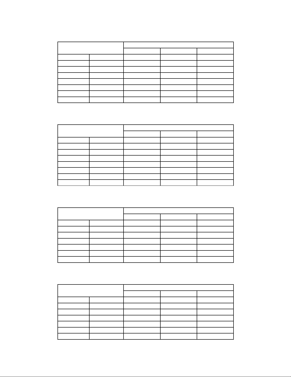
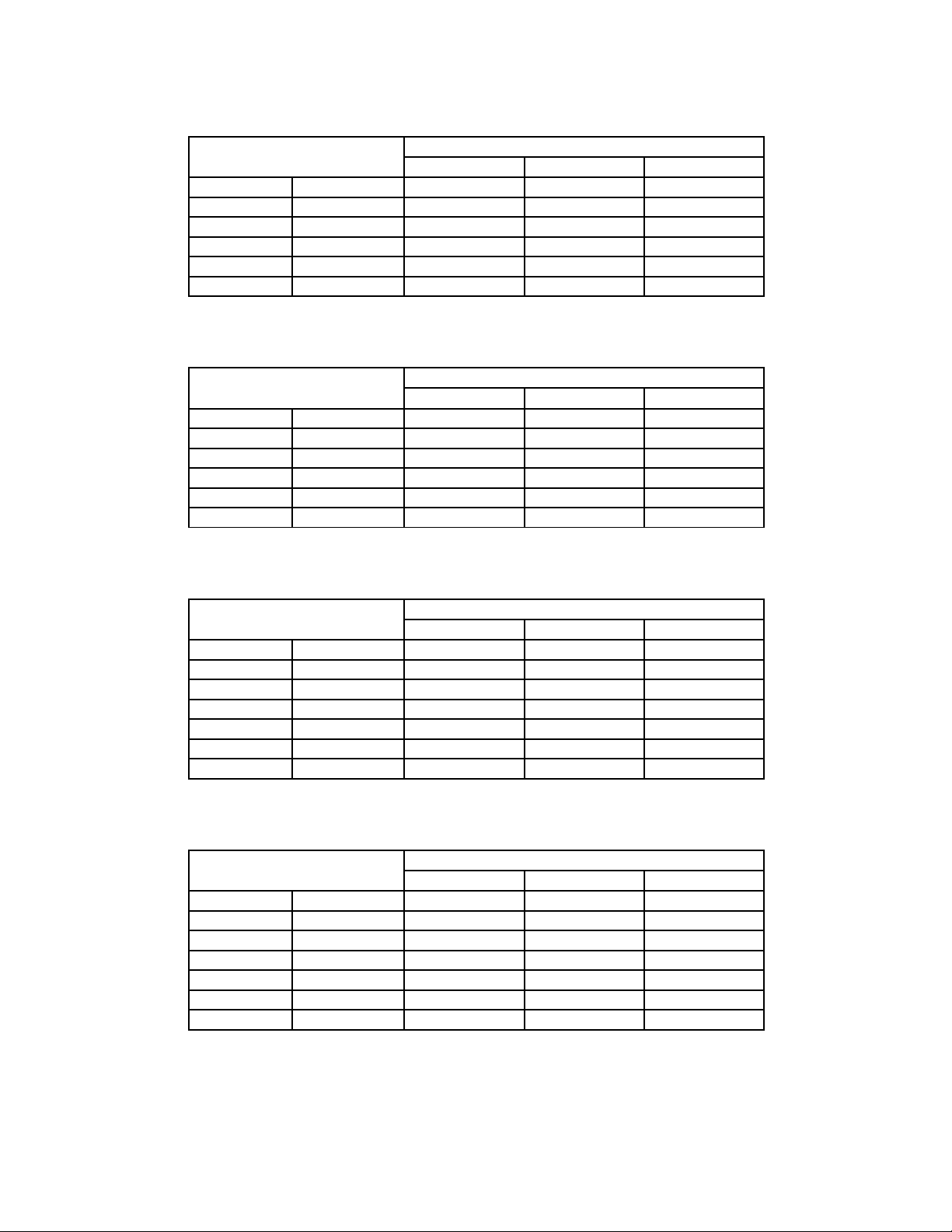
THERMOCOUPLE-ACCURACY TABLES
The following tables are provided to easily ascertain the maximum error allowed for the
thermocouple types supported. They apply when either sourcing or measuring temperature with
thermocouple wires. A 95% confidence level (k = 2) is assumed. The errors were derived using
the SS (root of the sum of the squares) of all the applicable sources for error. These errors
include:
1. Cold-junction compensation (if used without CJC, errors are reduced).
2. Variation of the environmental temperature by ±5°C from calibration temperature. If
a better temperature environment is maintained, errors will be reduced.
3. Noise, 1 µV peak in a “0.1 Hz to 10 Hz” bandwidth.
4. Accuracy, as listed on page 2-1 for periods of 30 days, six months, and one year.
5. Uncertainty limits (k = 2) of Ectron’s temperature measurement system, ±0.01°C.
6. Conformity, ±0.4 µV.
2-3

Specifications
Table 2-1: Type B Thermocouple (°C)
Temperature Ran e Error After:
30 Days Six Months One Year
250 <350 ±0.58 ±0.85 ±0.95
350 <445 ±0.41 ±0.60 ±0.74
445 <580 ±0.33 ±0.49 ±0.58
580 <750 ±0.26 ±0.38 ±0.45
750 <1000 ±0.21 ±0.31 ±0.37
1000 1820 ±0.17 ±0.24 ±0.29
Table 2-2: Type B Thermocouple (°F)
Temperature Ran e Error After:
30 Days Six Months One Year
482 <662 ±1.04 ±1.53 ±1.71
662 <833 ±0.74 ±1.08 ±1.33
833 <1076 ±0.59 ±0.88 ±1.04
1076 <1382 ±0.47 ±0.68 ±0.81
1382 <1832 ±0.38 ±0.56 ±0.67
1832 3308 ±0.31 ±0.43 ±0.52
Table 2-3: Type C Thermocouple (°C)
Temperature Ran e Error After:
30 Days Six Months One Year
0 <250 ±0.12 ±0.16 ±0.20
250 <1000 ±0.10 ±0.13 ±0.16
1000 <1500 ±0.11 ±0.15 ±0.18
1500 <1800 ±0.13 ±0.18 ±0.21
1800 <2000 ±0.14 ±0.20 ±0.23
2000 <2250 ±0.17 ±0.24 ±0.29
2250 2315.56 ±0.19 ±0.26 ±0.32
Table 2-4: Type C Thermocouple (°F)
Temperature Ran e Error After:
30 Days Six Months One Year
32 <482 ±0.22 ±0.29 ±0.36
482 <1832 ±0.18 ±0.23 ±0.29
1832 <2732 ±0.20 ±0.27 ±0.32
2732 <3272 ±0.23 ±0.32 ±0.38
3272 <3632 ±0.25 ±0.36 ±0.41
3632 <4082 ±0.31 ±0.43 ±0.52
4082 4200.01 ±0.34 ±0.47 ±0.58
2-4
Specifications
Table 2-5: Type D Thermocouple (°C)
Temperature Ran e Error After:
30 Days Six Months One Year
0 <100 ±0.16 ±0.23 ±0.27
100 <300 ±0.12 ±0.17 ±0.20
300 <1400 ±0.10 ±0.13 ±0.15
1400 <1650 ±0.10 ±0.15 ±0.17
1650 <1930 ±0.12 ±0.16 ±0.20
1930 <2100 ±0.14 ±0.19 ±0.23
2100 <2200 ±0.15 ±0.21 ±0.25
2200 2320 ±0.18 ±0.25 ±0.30
Table 2-6: Type D Thermocouple (°F)
Temperature Ran e Error After:
30 Days Six Months One Year
32 <212 ±0.29 ±0.41 ±0.49
212 <572 ±0.22 ±0.31 ±0.36
572 <2552 ±0.18 ±0.23 ±0.27
2552 <3002 ±0.18 ±0.27 ±0.31
3002 <3506 ±0.22 ±0.29 ±0.36
3506 <3812 ±0.25 ±0.34 ±0.41
3812 <3992 ±0.27 ±0.38 ±0.45
3992 4208 ±0.32 ±0.45 ±0.54
Table 2-7: Type E Thermocouple (°C)
Temperature Ran e Error After:
30 Days Six Months One Year
−270 <−245 ±0.95 ±1.10 ±1.20
−245 <−195 ±0.13 ±0.16 ±0.18
−195 <−155 ±0.07 ±0.09 ±0.10
−155 <−90 ±0.06 ±0.07 ±0.08
−90 <15 ±0.05 ±0.06 ±0.07
15 <890 ±0.05 ±0.06 ±0.06
890 1000 ±0.05 ±0.06 ±0.07
Table 2-8: Type E Thermocouple (°F)
Temperature Ran e Error After:
30 Days Six Months One Year
−454 <−409 ±1.71 ±1.98 ±2.16
−409 <−319 ±0.23 ±0.29 ±0.32
−319 <−247 ±0.13 ±0.16 ±0.18
−247 <−130 ±0.11 ±0.13 ±0.14
−130 <59 ±0.09 ±0.11 ±0.13
59 <1634 ±0.09 ±0.11 ±0.11
1634 1832 ±0.09 ±0.11 ±0.13
2-5

Specifications
Table 2-9: Type G Thermocouple (°C)
Temperature Ran e Error After:
30 Days Six Months One Year
0 <100 ±1.10 ±1.30 ±1.50
100 <300 ±0.28 ±0.35 ±0.43
300 <600 ±0.14 ±0.19 ±0.24
600 <1760 ±0.10 ±0.13 ±0.15
1760 <2030 ±0.11 ±0.15 ±0.18
2030 <2200 ±0.13 ±0.17 ±0.21
2200 2315.56 ±0.14 ±0.20 ±0.24
Table 2-10: Type G Thermocouple (°F)
Temperature Ran e Error After:
30 Days Six Months One Year
32 <212 ±1.98 ±2.34 ±2.70
212 <572 ±0.50 ±0.63 ±0.77
572 <1112 ±0.25 ±0.34 ±0.43
1112 <3200 ±0.18 ±0.23 ±0.27
3200 <3686 ±0.20 ±0.27 ±0.32
3686 <3992 ±0.23 ±0.31 ±0.38
3992 4200.01 ±0.25 ±0.36 ±0.43
Table 2-11: Type J Thermocouple (°C)
Temperature Ran e Error After:
30 Days Six Months One Year
−210 <−180 ±0.07 ±0.10 ±0.12
−180 <−120 ±0.06 ±0.09 ±0.10
−120 <−50 ±0.06 ±0.07 ±0.08
−50 <990 ±0.05 ±0.06 ±0.07
990 1200 ±0.05 ±0.07 ±0.07
Table 2-12: Type J Thermocouple (°F)
Temperature Ran e Error After:
30 Days Six Months One Year
−346 <−292 ±0.13 ±0.18 ±0.22
−292 <−184 ±0.11 ±0.16 ±0.18
−184 <−58 ±0.11 ±0.13 ±0.14
−58 <1814 ±0.09 ±0.11 ±0.13
1814 2192 ±0.09 ±0.13 ±0.13
2-6
Specifications
Table 2-13: Type K Thermocouple (°C)
Temperature Ran e Error After:
30 Days Six Months One Year
−270 <−255 ±1.50 ±1.90 ±2.20
−255 <−195 ±0.30 ±0.40 ±0.70
−195 <−115 ±0.10 ±0.11 ±0.12
−115 <−55 ±0.07 ±0.08 ±0.09
−55 <1000 ±0.06 ±0.07 ±0.07
1000 1372 ±0.06 ±0.08 ±0.08
Table 2-14: Type K Thermocouple (°F)
Temperature Ran e Error After:
30 Days Six Months One Year
−454 <−427 ±2.70 ±3.42 ±3.96
−427 <−319 ±0.54 ±0.72 ±1.26
−319 <−175 ±0.18 ±0.20 ±0.22
−175 <−67 ±0.13 ±0.14 ±0.16
−67 <1832 ±0.11 ±0.13 ±0.13
1832 2501.6 ±0.11 ±0.14 ±0.14
Table 2-15: Type N Thermocouple (°C)
Temperature Ran e Error After:
30 Days Six Months One Year
−270 <−260 ±3.50 ±4.00 ±5.00
−260 <−200 ±0.75 ±0.93 ±1.00
−200 <−140 ±0.15 ±0.19 ±0.23
−140 <−70 ±0.10 ±0.12 ±0.15
−70 <25 ±0.08 ±0.10 ±0.12
25 <160 ±0.07 ±0.09 ±0.10
160 1300 ±0.07 ±0.08 ±0.09
Table 2-16: Type N Thermocouple (°F)
Temperature Ran e Error After:
30 Days Six Months One Year
−454 <−436 ±6.30 ±7.20 ±9.00
−436 <−328 ±1.35 ±1.67 ±1.80
−328 <−220 ±0.27 ±0.34 ±0.41
−220 <−94 ±0.18 ±0.22 ±0.27
−94 <77 ±0.14 ±0.18 ±0.22
77 <320 ±0.13 ±0.16 ±0.18
320 2372 ±0.13 ±0.14 ±0.16
2-7

Specifications
Table 2-17: Type Platinel II Thermocouple (°C)
Temperature Ran e Error After:
30 Days Six Months One Year
0 <100 ±0.07 ±0.08 ±0.10
100 <925 ±0.06 ±0.07 ±0.08
925 <1200 ±0.07 ±0.08 ±0.10
1200 1395 ±0.08 ±0.09 ±0.11
Table 2-18: Type Platinel II Thermocouple (°F)
Temperature Ran e Error After:
30 Days Six Months One Year
32 <212 ±0.13 ±0.14 ±0.18
212 <1697 ±0.11 ±0.13 ±0.14
1697 <2192 ±0.13 ±0.14 ±0.18
2192 2543 ±0.14 ±0.16 ±0.20
Table 2-19: Type R Thermocouple (°C)
Temperature Ran e Error After:
30 Days Six Months One Year
−50 <−30 ±0.40 ±0.58 ±0.65
−30 <45 ±0.34 ±0.48 ±0.55
45 <160 ±0.24 ±0.32 ±0.40
160 <380 ±0.18 ±0.26 ±0.30
380 <775 ±0.15 ±0.21 ±0.26
775 1768.1 ±0.13 ±0.18 ±0.22
Table 2-20: Type R Thermocouple (°F)
Temperature Ran e Error After:
30 Days Six Months One Year
−58 <−22 ±0.72 ±1.04 ±1.17
−22 <113 ±0.61 ±0.86 ±0.99
113 <320 ±0.43 ±0.58 ±0.72
320 <716 ±0.32 ±0.47 ±0.54
716 <1427 ±0.27 ±0.38 ±0.47
1427 3214.58 ±0.23 ±0.32 ±0.40
2-8

Specifications
Table 2-21: Type S Thermocouple (°C)
Temperature Ran e Error After:
30 Days Six Months One Year
−50 <−30 ±0.38 ±0.53 ±0.62
−30 <45 ±0.32 ±0.47 ±0.56
45 <105 ±0.23 ±0.34 ±0.40
105 <310 ±0.20 ±0.30 ±0.33
310 <615 ±0.17 ±0.25 ±0.29
615 1768.1 ±0.15 ±0.22 ±0.26
Table 2-22: Type S Thermocouple (°F)
Temperature Ran e Error After:
30 Days Six Months One Year
−58 <−22 ±0.68 ±0.95 ±1.12
−22 <113 ±0.58 ±0.85 ±1.01
113 <221 ±0.41 ±0.61 ±0.72
221 <590 ±0.36 ±0.54 ±0.59
590 <1139 ±0.31 ±0.45 ±0.52
1139 3214.58 ±0.27 ±0.40 ±0.47
Table 2-23: Type T Thermocouple (°C)
Temperature Ran e Error After:
30 Days Six Months One Year
−270 <−255 ±1.40 ±1.60 ±1.80
−255 <−240 ±0.27 ±0.35 ±0.49
−240 <−210 ±0.17 ±0.24 ±0.30
−210 <−150 ±0.11 ±0.15 ±0.18
−150 <−40 ±0.08 ±0.10 ±0.12
−40 <100 ±0.06 ±0.07 ±0.08
100 400 ±0.05 ±0.06 ±0.07
Table 2-24: Type T Thermocouple (°F)
Temperature Ran e Error After:
30 Days Six Months One Year
−454 <−427 ±2.52 ±2.88 ±3.24
−427 <−400 ±0.49 ±0.63 ±0.88
−400 <−346 ±0.32 ±0.43 ±0.54
−346 <−238 ±0.20 ±0.27 ±0.31
−238 <−40 ±0.14 ±0.18 ±0.20
−40 <212 ±0.11 ±0.13 ±0.14
212 752 ±0.09 ±0.11 ±0.13
2-9

Specifications
This page intentionally left blank.
2-10
Table of contents
Popular Test Equipment manuals by other brands

PeakTech
PeakTech 1145 Operation manual

IMI SENSORS
IMI SENSORS 699A07 Installation and operating manual

Smart Tweezers
Smart Tweezers Iskra ST5L manual

PCB Piezotronics
PCB Piezotronics 498A-0015 Installation and operating manual

Sunlight Electronics Laboratory
Sunlight Electronics Laboratory 7116C Operation manual

Apera Instruments
Apera Instruments PH60-E How to replace


