Sunlight Electronics Laboratory 7116C User manual

MODEL – 7116C
OPERATION MANUAL
Mar. 26 , 2008
Sunlight Electronics Laborator
y
490, Sec. 2, Chung Shan Rd., Chung Ho, Taipei, Taiwan 23557
Tel :+886 2 2222 3759
Fax : +886 2 2223 0727
htt
p
://www.sunlilab.com.t
w

... CONTENT ...
OPERATION GUIDE ( ENGLISH VERSION )
A. MODEL - 7116C AUDIO SWEEPER
Ⅰ. PANEL INTRODUCTION ---------------------------------------------------------------------------------- (2)
Ⅱ. 7116C CAN BE USED IN THREE WAYS --------------------------------------------------------- (3)
Ⅲ. MEASURING THE LOWEST RESONANT FREQ. Fo OF A SPEAKER ----------------- (4)
Ⅳ. SPECIFICATIONS -------------------------------------------------------------------------------------------- (5)
B. PRIMARY TROUBLE SHOOTING AND MAINTAINANCE
Ⅰ. POWER PORTION ------------------------------------------------------------------------------------------ (6)
Ⅱ. OUTPUT SIGNAL VOLTAGE PORTION ------------------------------------------------------------ (7)
Ⅲ. REGULATED POWER SUPPLIES OF +12V DC & -12V DC ----------------------------- (8)
Ⅳ. HOW TO JUDGE WHETHER THE 〝PAAS 〞PCB IS FAULTY -------------------------- (9)
Sunlight Electronics Laborator
y
490, Sec. 2, Chung Shan Rd., Chung Ho, Taipei, Taiwan 23557
Tel : +886 2 2222 3759
Fax : +886 2 2223 0727
htt
p
://www.sunlilab.com.t
w
- 1 -

AUDIO SWEEPER Model-7116C
Ⅰ. Panel Introduction
13 14 567
10 11 92384
1 12
7116C provides pure sine wave with very low total harmonic distortion. (approx. 0.1%
THD ). The total harmonic distortion of 7116C consists of 2nd Harmonic component only
and nearly without higher order harmonic components. So, 7116C is very suitable to test
the sound quality ( spurious noise inspection ) of all kinds of loudspeaker, headphone,
receivers, piezo, speakers system…etc.
The frequency produced by 7116C is more stable than the ordinary beat frequency
oscillator produced. and the sine wave provided by 7116C is purer than the ordinary
function generator. Therefore, 7116C has both advantages of low distortion and high
stability. do not use the ordinary function generator to test the spurious noise ( rattle
and buzz ) of loudspeaker, loudspeaker, receiver, etc.…Because user will easily neglect
the prohibited spurious noise caused originally from the high order distortion component
of the function generator.
1. Power: power switch & indicator
2. Fo: The lowest resonant frequency Fo test pushbutton.
3. Start: By depressing this button, The desired start frequency can be set by adjusting
the coarse knob (5) and fine knob (6) of 〝Start 〞. the start frequency can
be set in the range of 20Hz to 20KHz. the frequency will be displayed on
〝Frequency Counter (14) 〞in the front panel.
4. Stop: By depressing this pushbutton, The stop frequency can be set adjusting the
stop knob (7). The stop frequency also can be set in the range of 20Hz to
20KHz and can be displayed on 〝Frequency Counter (14) 〞in the panel.
- 2 -

5. Coarse ( Start ) : The coarse knob of start adjustment for setting the start frequency.
Please depress the start pushbutton before adjusting the coarse
knob.
6. Fine ( Start ): The fine knob of start adjustment for setting the start frequency.
This knob is convenience for researching the lowest resonant
frequency because the frequency variation is tiny.
7. Stop: The stop knob of stop adjustment for setting the stop frequency.
Remember to set the stop frequency always higher than the start
frequency.
8. Auto / Manu: When depressing the button, The output signal of 7116C will
sweep forth and back automatically between the range set by the
start adjustment knobs and stop adjustment knob. If button (3) or
(4) is depressed, The 7116C will output a signal of constant
frequency by adjusting start knobs or stop knob, And 7116C will
be functioned as a manual sweep generator.
9. Sweep: Sweep time control knob with scale in second. Sweep time is
continuously adjustable in the range of 0.3 sec. to 40 sec.
10. Coarse ( Volume ): For adjusting the output voltage in great variation.
11. Fine ( Volume ): For adjusting the output voltage in small variation.
12. Output: The output terminals to the tested item.
13. Output Voltage Meter: A digital autoranging R.M.S. voltage meter indicating the
voltage from the output terminal.
14. Frequency: 4 digits display, 20Hz~20KHz, Resolution: 1 Hz counter.
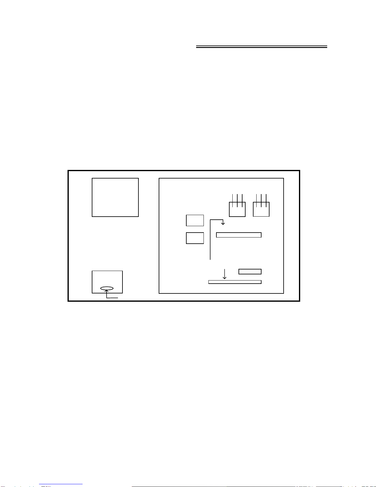
Ⅱ. 7116C Can Be Used In Following Three Ways
1. Automatic Sweep Generator :
Depress Auto / Manu (8) pushbutton, Then 7116C will sweep forth and back between
the frequencies set by start adjustment knobs and stop knob.
2. Manual Sweep Generator :
Depress start (3) or stop (4) pushbutton, adjust Start / Stop coarse knob.
3. A Constant Frequency Generator :
Depress start (3) or stop (4) pushbutton, And adjust start Coarse / Fine knob (5) / (6)
or stop knob (7) to the frequency desired.
- 3 -

Ⅲ. Measuring The Lowest Resonant Frequency Fo Of A Loudspeaker
The lowest resonant frequency of a midrange or a tweeter is a very important
parameter when designing the speaker system. And the lowest resonant frequency
of a woofer would affect the regeneration of low frequency greatly. Therefore, It’s
necessary to measure the Fo value of each kinds of loudspeaker. And 7116C can
measure the Fo value manually.
1. Connect the loudspeaker to the output terminal of 7116C.
2. depress the Fo pushbutton (2).
3. Adjust the output voltage to approximately 0.5V.
4. Adjust the start Coarse / Fine knob, To start at 20Hz up to a higher frequency
slowly. ( Especially slowly for the woofer ) The voltage value will increase as the
frequency increasing. A maximum voltage should be reached at a certain frequency,
And the voltage value will fall down when the frequency goes higher again. Please
turn the start Coarse / Fine knob back to the frequency at the highest voltage, And
the frequency is the lowest resonant frequency of the loudspeaker at that voltage.
5. In EIA standard, It is recommended to test the Fo value with 1.0V ±10% voltage
across the terminals of the loudspeaker. So user should adjust the voltage volume
to 1.0V after the Fo value was found. Then repeat steps 1. to 4, To make sure
that the lowest resonant frequency found is exactly at the highest voltage of 1.0V
±10%.
Note :
It would obtain the different Fo values at the different voltages. and most
countries has their own definition for measuring the Fo value. For example: Taiwan
and Japan do not apply 1.0V to test the Fo value. Therefore, It is necessary to
define the measuring condition when providing the specification of the Fo value.
6. However, This measuring speed for researching the Fo value is too slow in
production line. Using the〝Digital High Speed Fo Meter Model - 7117K 〞would be
the most adequate instrument in the production line for undergoing 100%
inspection.
- 4 -

Ⅳ. Specification
1. Frequency Range: Cover 20Hz to 20KHz in one range, ( usually under 15Hz
and higher than 21KHz ).
2. Frequency Counter: 4 digits display, resolution 1Hz, accuracy ±1Hz.
3. Signal: Sine Wave, THD. < 0.15% ( 1KHz, 10V ), THD. 0.1% typical.
4. Power Output: 7116C ( 20W ) 0-12.6V 8 OHMS load.
( At rated line 0-9.0V 4 OHMS load.
voltage ) 7116C ( 60W ) 0-22.0V 8 OHMS load.
0
-15.5V 4 OHMS load.
7116C ( 100W ) 0-28.3V 8 OHMS load.
0
-20.0V 4 OHMS load.
Continuously adjustable with short circuit protection.
5. Voltage Meter: 3
3/4Digits, autorange ( Two Ranges ).
Low Range: 0.000V-3.300V ( Approx. )
Resolution 0.001V
High Range: 3.30V-38.00V ( Approx. )
Resolution 0.01V
Accurancy: ±0.6% of reading ±2dgts.
6. Output Protection Circuit:
Triple-protection, The amplifier won’t be burnt out even if the output terminal
is continuously shorted all day long. The output terminal will become an open
circuit when the load is shorted, And will have power output again automatically
when the shorted condition was vanished.
7. Sweeping Mode: Logarithmic Sweep.
8. Sweeping Width: Maximum ratio is 1:1000, 20Hz to 20KHz in one sweep.
9. Sweep Time: 0.3~40 SEC., Continuously adjustable.
10. Power Consumption: 7116C ( 20W ) 45VA Max.
7116C ( 60W ) 100VA Max.
7116C ( 100W ) 160VA Max.
11. Min. Loading impedance : must be > 3.2Ω
12. Dimension: 37 ( L ) ×28 ( W ) ×13 ( H ) Cm.
13. Weight: 7116C ( 20W ) 6.0 KGS. Approx.
7116C ( 60W ) 8.0 KGS. Approx.
7116C ( 100W ) 10.0 KGS. Approx.
Primary Trouble Shooting And Maintenance
- 5 -

Ⅰ. Power Portion
In case after power on, indicator of Model - 7116C did not light up, no digits
displayed on two Liquid Crystal Displays ( LCD ), and no single function occurred, then,
users are required to check the fuse at the rear panel of 7116C, if fuse was burnt
out, replace a new fuse with the same spec., if fuse is O.K., users may undergo
primary trouble shooting by following the procedures of below- mentioned, to detect
which PCB is faulted, or users may contact either Sunlight's agent or directly with
Sunlight, to discuss on the matter of how to repair the faulted Model - 7116C.
Remarks :
Burnt out of fuse is usually caused in following circumstances :
A. Internal circuit severely damaged, faulted 7116C should send back to Sunlight for
repair.
Sunlight Electronics Laborator
y
490, Sec. 2, Chung Shan Rd., Chung Ho, Taipei, Taiwan 23557
Tel : +886 2 2222 3759
Fax : +886 2 2223 0727
htt
p
://www.sunlilab.com.t
w
B. Misconnection of power to higher line voltage, causing the permanent damage of
an internal metal oxide varistor, in this case, it is in vain to replace only a new
fuse, instead, users should replace first a new metal oxide varistor, then, replace
a new fuse, otherwise, the replaced fuse will still be burnt out again. If users
have no 〝Metal Oxide varistor 〞on hand, they may cut off the metal oxide
varistor, but without the varistor, when misconnection of power occurred, the
circuit of Model - 7116C will no longer be protected. ( Metal Oxide Varistor is
round in shape, & is about 1 cm. in diameter, it is fixed on the position as below
Fig. shown. For 220V and 110 power voltage, a metal oxide varistor with code
no.: of 〝471K 〞& 〝221K 〞are being used respectively.
- 6 -

Ⅱ. Output Signal Voltage Portion
A. If output terminals have no signal, users are required to check whether the
Frequency Counter (14) has displayed value, if displayed occurred, oscillator circuit
of 7116C is in normal function. Recheck whether the ACV Voltmeter (13) has
displayed voltage, if no voltage displayed ( 0.000V appeared ), then, portion of
amplifier is faulty, the 〝PAAS 〞PCB should be sent back to Sunlight for repair.
B. If frequency meter has no displayed also, then, either the 〝716SW 〞PCB or
regulator circuit might be faulted. Users, please uncover the top cover ( inner
appearance of Model - 7116C as below Fig. shown ).
Inner Top View Of 7116C
PAAS.P.C.B.
TRANSFORMER
RELAY
RELAY
7812 7912
COMPONENT SIDE
716SW.P.C.B.
TNR
The PCB nearest to the front panel is 〝716SW 〞PCB, which is the oscillator
circuit and control center of 7116C, 〝716SW 〞PCB has several points ( points for
testing and to judge whether PCB is faulty. )
“ G ” is ground of 7116C.
“ +12 ” means should have a regulated voltage of +12V DC against ground.
“ -12 “ means should have a regulated voltage of -12V DC against ground.
“ AC1V “ means should have a sine wave output of 1V AC.
Check first the +12V DC and -12V DC, if both are normal, check if
the ”AC1V“ measuring point is normal, if no signal occurred, users are required to
send back 〝716SW 〞PCB to Sunlight for repair.
If either the +12 DC or -12 DC is abnormal, disconnect the “716SW” PCB &
undergo following checking procedures.
- 7 -

Ⅲ. Regulated Power Supplies Of +12V DC And -12V DC On Mother Board
A. Use a voltmeter to check whether the regulated power supplies of both +12V
DC and -12V DC are in good condition. Mother board has two regulators:
〝7812 〞for +12V DC regulators “7912” for -12V DC regulator ( as Fig. shown ).
Check whether both the “7812” & “ 7912” regulators are in normal functions, if
both or either one is faulted, users may buy new regulators with the same type
no., to replace the faulty one. ( To replace a new regulator, users are required
to unfasten the screws on mother board and cut off pins of the faulted regulator,
then, weld on the new regulator to its appropriate position, and fasten the
screws. )
-12V
GROUND
Vin
7912
+12V
GROUND
Vin
7812
Regrlator 7812 & 7912 On Mother Board
B. After replacing the “7812” & 〝7912 〞regulators, if inserted the〝716SW 〞PCB,
±12V DC voltages appeared in abnormal functions, while disconnected the
〝716SW 〞PCB, ±12V DC voltages have reverted to their normal functions,
then, it means that 〝716SW 〞PCB is faulted, it should be replaced by a fine
one, or it needs to repair.
Remarks :
In case users had judged that 〝PAAS 〞PCB is faulted, & wish to post back
the faulty PCB to Sunlight for repair, they are requested to mail back also the
power transistors positioned on the heat sink at the rear panel of 7116C ( users
need to disconnect the say power transistors ), since usually, when the 〝PAAS 〞
PCB is faulted, the power transistors are faulted also.
But to send back the whole set of 7116C or the 〝716SW 〞PCB for repair,
users need not have to disconnect the say power transistors.
- 8 -

Ⅳ. How To judge whether The〝PAAS 〞PCB is faulty
If according to the (II) procedures, users had judged that the〝716SW 〞PCB is
faulted, before sending it back for repair, users may judge whether the 〝PAAS 〞
PCB is faulty also, its method as follows:
A. Disconnect the 〝716SW 〞PCB.
B. Use a signal generator to feed sine wave of 0.1V to 1V to〝Hi 〞terminal of
coarse knob's VR ( volume control ), then, turn the 〝COARSE 〞knob of volume
control, if voltmeter displayed output value, it means 〝PAAS 〞PCB is O.K., if
users have no signal generator on hand, they may use a small screwdriver
( should hold its metallic portion ), to touch the〝Hi 〞terminal of coarse knob's
VR ( volume control ), this method will have the same effect as using the signal
generator.
The above Fig. is the track
side of 〝716SW 〞PCB,〝8〞
marks are the test points measured
by the users, users may test
whether the direct or alternate
voltage of the 〝8〞marks are
normal ( follow the afore-mentioned
procedures ), thereby judging which
PCB of 7116C is faulty.
716SW K
AC 1V
G
+12V
-12V8
8
8
8
Inner Top View Of 7116C
PAAS.P.C.B.
TRANSFORMER
TNR
RELAY
RELAY
7812 7912
COMPONENT SIDE
716SW.P.C.B.
R2 R3 R4R1
7116C (20W) 7116C (60W) 7116C (100W)
Resistor R1 0.5Ω/ 2W 0.5Ω/ 2W 0.5Ω/ 2W
Resistor R2 0.5Ω/ 2W 0.5Ω/ 2W 0.5Ω/ 2W
Resistor R3 Not Required Not Required 0.5Ω/ 2W
Resistor R4 Not Required Not Required 0.5Ω/ 2W
- 9 -

Sunlight Electronics Laborator
y
490, Sec. 2, Chung Shan Rd., Chung Ho, Taipei, Taiwan 23557
Tel : +886 2 2222 3759
Fax : +886 2 2223 0727
htt
p
://www.sunlilab.com.t
w
- 10 -
Table of contents