Edan Instruments, Inc. VE-300 User manual

EDAN INSTRUMENTS, INC.
Manual Ver: V1.2
Release Date: March 2009
Part Number: MS1R-107182-V1.2
VE
-
300
Veterinary Electrocardiograph

-I-
Copyright
Copyright EDAN INSTRUMENTS, INC. 2008-2009. All rights reserved.
Statement
This manual will help youunderstand the operation and maintenance of the product better.Itis
reminded that the product shall be used strictlycomplyingwith this manual. User’soperation
failingto complywith this manual mayresult in malfunction or accident for which Edan
Instruments, Inc. (hereinafter called EDAN) can not be held liable.
EDAN owns the copyrights of this manual. Without prior written consent of EDAN, any
materials contained in this manual shall not be photocopied, reproduced or translated into other
languages.
Materials protected bythe copyright law,includingbutnot limited to confidential information
such as technical information and patent information are containedin this manual, the user shall
not disclose such information to anyirrelevant third party.
The user shall understandthat nothingin this manual grants him, expresslyor implicitly,any
right or license to use anyof the intellectual properties of EDAN.
EDAN holds the rights to modify, update, and ultimatelyexplain this manual.
Responsibility of the Manufacturer
EDAN onlyconsiders itself responsible for anyeffect on safety,reliabilityand performance of
the equipment if:
Assemblyoperations, extensions, re-adjustments, modifications or repairs are carried out by
persons authorized byEDAN, and
The electrical installation of the relevant room complies with national standards, and
The instrument is used in accordance with the instructions for use.
Upon request, EDAN mayprovide, with compensation, necessarycircuitdiagrams, and other
information to help qualified technician to maintain and repair some parts, which EDAN may
define as user serviceable.
P/N MS1R-107182-V1.2

-II-
Using This Label Guide
This guide is designed togive keyconcepts on safetyprecautions.
WARNING
AWARNING label advises against certain actions or situations that could result in personal
injuryor death.
CAUTION
ACAUTION label advises against actions or situations that could damageequipment, produce
inaccurate data, or invalidate a procedure.
NOTE:A NOTE provides useful information regardinga function or a procedure.
Revision History
Date ECO# Version Description
2008.01 V1.0 1st edition
2008.08 ECO-QR-8029 V1.1 2nd edition
2009.03 ECO-SE-9005 V1.1 Added some informationaccording
to FDA

-III-
Table of Contents
1 SafetyGuidance...................................................................................1
1.1 Intended use.................................................................................................................1
1.2 Safety Warnings...........................................................................................................1
1.3 BatteryCare Warnings................................................................................................3
1.4 General Cautions.........................................................................................................4
1.5 Cleaning & Disinfection Cautions..............................................................................5
2 Introduction..........................................................................................6
2.1 Function Features........................................................................................................6
2.2 List of Symbols.............................................................................................................7
3 General Information...........................................................................10
3.1 Top Panel....................................................................................................................10
3.1.1 LCD Screen......................................................................................................10
3.1.2 Control Panel and Keys..................................................................................11
3.2 Patient Cable Socket and Signal Interface............................................................14
3.3 MainsConnection and Switch.................................................................................17
3.4 Rear Panel..................................................................................................................17
3.5 Bottom Panel..............................................................................................................18
4 Operation Preparations.....................................................................21
4.1 Power and Earthing...................................................................................................21
4.2 Loading/Replacing Record Paper...........................................................................22
4.3 Patient Cable Connection.........................................................................................23
4.4 Electrode Connection................................................................................................24
4.5 Inspection before Power-On....................................................................................25
5 Operation Instructions......................................................................27
5.1 Switching On ..............................................................................................................27
5.2 AUTO Mode................................................................................................................27
5.3 MANUALMode..........................................................................................................28
5.4 RHYTHM mode..........................................................................................................28
5.5 USBPRTmode...........................................................................................................29
5.6 ECG Recall Operation..............................................................................................29
5.6.1 ECG Recall.......................................................................................................29
5.6.2 ECG Copy ........................................................................................................32
5.7 Using the Menu System ...........................................................................................33
5.7.1 Entering and Exiting the Menu......................................................................33
5.7.2 Moving in the Sub-menus..............................................................................33
5.7.3 Parameter Modification ..................................................................................33
5.8 Settings .......................................................................................................................33
5.8.1 Filter Settings...................................................................................................33

-IV-
5.8.2 Record Settings...............................................................................................34
5.8.3 Record Output Settings..................................................................................35
5.8.4 Other Record Settings....................................................................................36
5.8.5 Save and Transmitting Settings....................................................................37
5.8.6 General Settings..............................................................................................38
5.8.7 System Settings...............................................................................................39
5.8.8 Default Settings...............................................................................................40
5.9 AUTO mode record....................................................................................................42
5.10 RHYTHM mode record...........................................................................................44
5.11 USBPRTmode record............................................................................................46
5.12 Switch Off..................................................................................................................47
6 Hint Information.................................................................................48
7 Technical Specifications...................................................................49
8 Cleaning, Care and Maintenance......................................................52
8.1 Cleaning......................................................................................................................52
8.1.1 Cleaning the Main Unit and Patient Cable..................................................52
8.1.2 Cleaning the Electrodes.................................................................................52
8.1.3 Cleaning the Print Head.................................................................................52
8.2 Disinfection.................................................................................................................53
8.3 Care and Maintenance .............................................................................................53
8.3.1 Recharge and Replacement ofBattery........................................................53
8.3.2 Record Paper...................................................................................................54
8.3.3 Maintenance ofMain Unit, Patient Cable & Electrodes............................54
9 Warrantyand Service Policy.............................................................57
9.1 Warranty......................................................................................................................57
9.2 Service Policy.............................................................................................................57
10 Accessories......................................................................................59
11 EMCInformation - Guidance and Manufacture sDeclaration.......60
11.1 Electromagnetic Emissions- for all EQUIPMENTand SYSTEMS..................60
11.2 Electromagnetic Immunity- for all EQUIPMENTand SYSTEMS....................60
11.3 Electromagnetic Immunity-for EQUIPMENTand SYSTEMS that are not
LIFE-SUPPORTING ........................................................................................................61
11.4 Recommended Separation Distances..................................................................63

VE-300 VeterinaryElectrocardiograph User Manual
-1-
1 SafetyGuidance
Inorder to use the electrocardiograph safelyand effectively,avoidingpossible dangers caused
byimproper operations, please read throughthe user manual and be sure to be familiar with all
functions of the equipment and proper operation procedures before use.
Please paymore attention to the followingwarningand caution information.
1.1 Intended use
The intended useof VE-300 VeterinaryElectrocardiographis to acquire ECG signals from
animals through bodysurface with ECG electrodes. The VE-300 VeterinaryElectrocardiograph
is onlyintendedto be used in animal hospitals or animal clinics byveterinarians. The
cardiogram recordedbythe electrocardiograph can help users to analyze and diagnose heart
disease.
1.2 SafetyWarnings
WARNING :
1. The electrocardiograph is provided for the use ofqualified physicians or
personnel professionallytrained. Theyshouldbe familiar with the contents of
this user manual before operation.
2. Onlyqualified service engineers can installthis equipment, and onlyservice
engineers authorized byEDAN can open the shell.
3. Onlyqualified installation or service engineerscan shift the mains shift switch
(100V~115V/220V~240V) according to local mains supply.
4. The results given bythe equipment shouldbe examined with respect to the
overall clinical condition ofthe animal, and it can not substitute for regular
checking.
WARNING :
5. EXPLOSION HAZARD-Do not use the electrocardiograph in the presenceof
flammable anesthetic mixture with oxygen orother flammable agents.
6. SHOCK HAZARD-The power receptaclemust be ahospitalgrade grounded
outlet. Never tryto adapt the three-prong plug to fit a two-slot outlet.

VE-300 VeterinaryElectrocardiograph User Manual
-2-
7. If the integrityof external protectiveconductor in installation or arrangement is
in doubt, the equipment should be operated byusing abuilt-in rechargeable
battery.
8. Do not use this equipment in the presence ofhigh static electricityor high
voltage equipment which maygenerate sparks.
9. This equipment is not designed for direct cardiac application.
WARNING :
10. Onlypatient cable and other accessories supplied byEDAN can be used. Or
else, the performance and electric shock protection can not be guaranteed.
11. Be sure that all electrodes havebeen connected to the animal correctlybefore
operation.
12. Ensure that the conductivepartsofelectrodes and associated connectors,
including neutral electrode, do not come in contact with earth oranyother
conducting objects.
13. Electrodes with defibrillator protection should be used while defibrillating.
14. There is no danger for animals with pacemaker.However,ifapacemaker is
used, the resultsgivenbythe equipment maybe invalid, or losethe clinical
significance.
15. Do not touch the animal, bed, table and the equipment while using defibrillator
or pacemaker simultaneously.
16. In order to avoid burning, please keep the electrode far awayfrom the radio
knife while using electrosurgical equipment simultaneously.
17. If you use electrode gel with reusable electrodes during defibrillation, the ECG
recovery will be greater than 10 seconds. EDAN recommends the useof
disposable electrodes at all times.
WARNING :
18. Accessoryequipment connected to the analog and digital interfaces mustbe
certified according to the respectiveIEC/EN standards (e.g. IEC/EN 60950 for
dataprocessing equipment and IEC/EN 60601-1 for medical equipment).
Furthermore all configurations shall complywith the valid version ofthe
standard IEC/EN 60601-1-1. Therefore anybody,who connectsadditional
equipment to the signal input connector or output connector to configure a

VE-300 VeterinaryElectrocardiograph User Manual
-3-
medical system, mustmake sure that it complies with the requirementsof the
valid version of the system standard IEC/EN 60601-1-1. Ifin doubt, consult our
technical service department or your local distributor.
19. The summation ofleakage current should never exceed leakage current limits
while several other units are used at the same time.
20. The potentialequalization conductor can be connected to that of other
equipment when necessary,to make surethat all theseequipment are
connected with the potential equalization busbar ofthe electrical installation.
1.3 BatteryCareWarnings
WARNING :
21. Improper operation maycause the batteryto be hot, ignited or exploded, and it
maylead to the declination ofbatterys capacity. It is necessaryto read the user
manual carefullyand paymore attention to warning messages.
22. Onlyqualified service engineer authorized byEDAN can open the battery
compartment and replace the battery,and the batteryof same model and
specification provided bymanufacturer should be used.
23. Danger ofexplosion -- Do not reverse the anode and cathode when connecting
the battery.
24. Do not heat or splash the batteryor throwit into fire or water.
25. When leakage or foul smell is found, stop using the batteryimmediately.If your
skin or cloth comes into contactwith the leakage liquid, cleanse it with clean
water at once. If the leakage liquid splashesinto your eyes, do not wipe them.
Irrigate them with clean water first and go to see a doctor immediately.
26. When the batterysuseful life isover,contact with the manufacturer or local
distributor for disposal or dispose the batteryaccording to local regulations.
27. When the batterysuseful lifeis over,contactthe manufacturer or local
distributor for disposal or dispose the batteryaccording to local regulations.

VE-300 VeterinaryElectrocardiograph User Manual
-4-
1.4 General Cautions
CAUTION :
1. Avoid liquid splash and excessivetemperature. The temperaturemust be kept
between 5 and 40 while working, and it should be kept between -20 and
55 during transportation & storage.
2. Do not usethe equipment industyenvironment with bad ventilation or inthe
presence of corrosive.
3. Be sure that there is no intense electromagnetic interference source around the
equipment, suchas radio transmitter ormobile phone etc. Attention: large
medical electrical equipment such as electrosurgical equipment, radiological
equipment and magnetic resonance imaging equipment etc. are likelyto bring
electromagnetic interference.
CAUTION :
4. Before use, the equipment, patient cable and electrodes etc. shouldbe
checked. Replacement should be taken ifthere is anyevident defectiveness
or aging symptom which mayimpair the safetyor performance.
5. The following safetychecks should be performed at least every24 months bya
qualified person who hasadequate training, knowledge, and practical
experience to perform these tests.
a) Inspectthe equipment and accessoriesformechanical and functional
damage.
b) Inspect the safetyrelevant labels for legibility.
c) Inspectthe fuse to verifycompliancewith rated current and breaking
characteristics.
d) Verifythe device functions properlyas described in the instructions for
use.
e) Testthe protection earth resistanceaccording to IEC/EN 60601-1: Limit
0.2 ohm.
f)Testthe earth leakage current according to IEC/EN 60601-1: Limit: NC
500 uA, SFC 1000uA.
g) Testthe patient leakage current according to IEC/EN 60601-1: Limit: 10
uA(CF).

VE-300 VeterinaryElectrocardiograph User Manual
-5-
h) Testthe patient leakage current undersingle fault condition with mains
voltage on the applied part according to IEC/EN 60601-1: Limit: 50uA
(CF).
The data should be recorded inan equipment log. If the device is not
functioning properlyor fails anyofthe abovetests, the device has to be
repaired.
6. Ruptured fuse must onlybe replaced with that of the same type and rating as
the original.
7. The device and accessories are to be disposed ofaccording to local regulations
after their useful lives. Alternatively,theycan be returned to the dealer or the
manufacturer for recycling or proper disposal.
8. Federal (US) lawrestricts this device to sale byor on the order ofaveterinarian.
1.5 Cleaning & Disinfection Cautions
CAUTION :
9. Turn offthe power before cleaning and disinfection. Ifmains supply used, the
power cord should be drugged out of the outlet also. Prevent the detergent from
seeping into the equipment.
10.Do not immerse the unit or patient cable into liquid under anycircumstances.
11. Do not clean the unit and accessories with abrasivefabric and avoid scratching
the electrodes.
12. Anyremainder ofdetergent should be removed from the unit and patient cable
after cleaning.
13. Do not use chloric disinfectant such as chloride and sodium hypochlorite etc.

VE-300 VeterinaryElectrocardiograph User Manual
-6-
2 Introduction
VE-300 veterinaryelectrocardiograph is 3-channel electrocardiographs with 7leads gathered
simultaneously,visual displayof operation menu, ECG parameters as well as
electrocardiogram.
3-channel ECG can beviewed on the LCD (liquid crystal display)screen of veterinary
electrocardiograph simultaneously, and it can be recorded byhigh-qualitythermal recorder.
Auto, manual, rhythm, USB print and off mode can be chosen freely.
Either mains supplyor built-in rechargeable Lithium batterycan be used as power.
With ahighresolution thermal printer,a32-bit processor and ahugecapacitymemorizer,
VE-300 has advanced performance and highreliability,and the compact size makes it suitable
for clinic and hospital use.
Configuration:Main unit and accessories (power cord, earth wire, patient cable, electrodes
and thermal record paper)
WARNING :This equipment is not designed for direct cardiac application.
WARNING :The results given bythe equipment should be examined with
respect to the overall clinical condition ofthe animal. And it can
not substitute for regular checking.
2.1 Function Features
♦Low weight and compactsize
♦Touch keyfor easyoperation
♦High resolution thermal recorder, recordingfrequencyresponse ≤150Hz
♦7-lead sampled and amplified simultaneously, 3-channel built-in recorder
♦Auto mode, manual mode, rhythm mode, USB print mode and off mode optional
♦Auto measurement function
♦Built-in rechargeable Libatterywith highcapacity
♦Hint information for leadoff, lack of paper and low batterycapacityetc.

VE-300 VeterinaryElectrocardiograph User Manual
-7-
♦Automatic adjustment of baseline for optimal recording
♦Standard input/output interface, RS232 communication interface andnet port for
linkingto special network and settingup ECG database
2.2 List of Symbols
External output
External input
Equipment or part of CF type with defibrillator proof
Attention –general warning(see accompanyingdocument)
Potential equalization
Mains supply
On (mains supply)
Off (mains supply)
Batteryindicator
Batteryrechargingindicator
Sensitivityswitch key
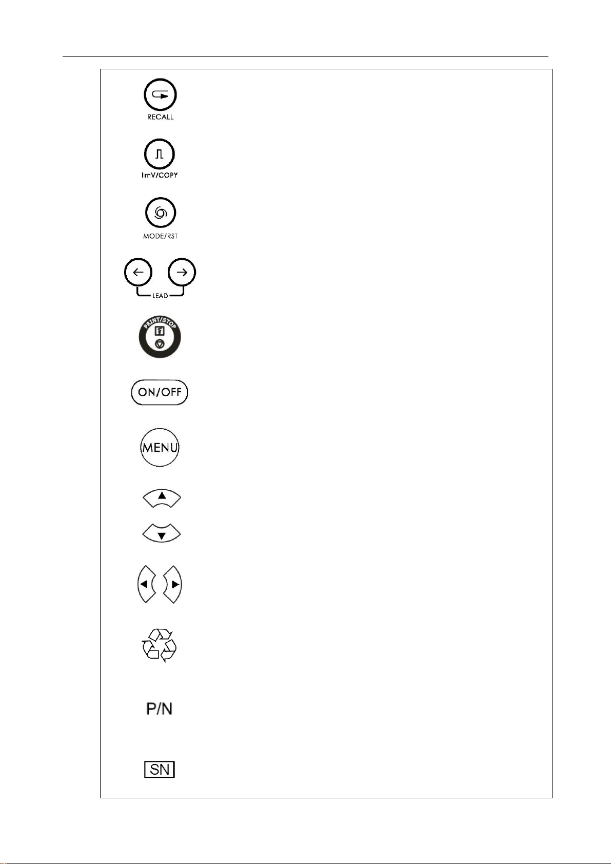
VE-300 VeterinaryElectrocardiograph User Manual
-8-
Recall key
1mVcalibration key& Copykey
Mode/RSTswitch key
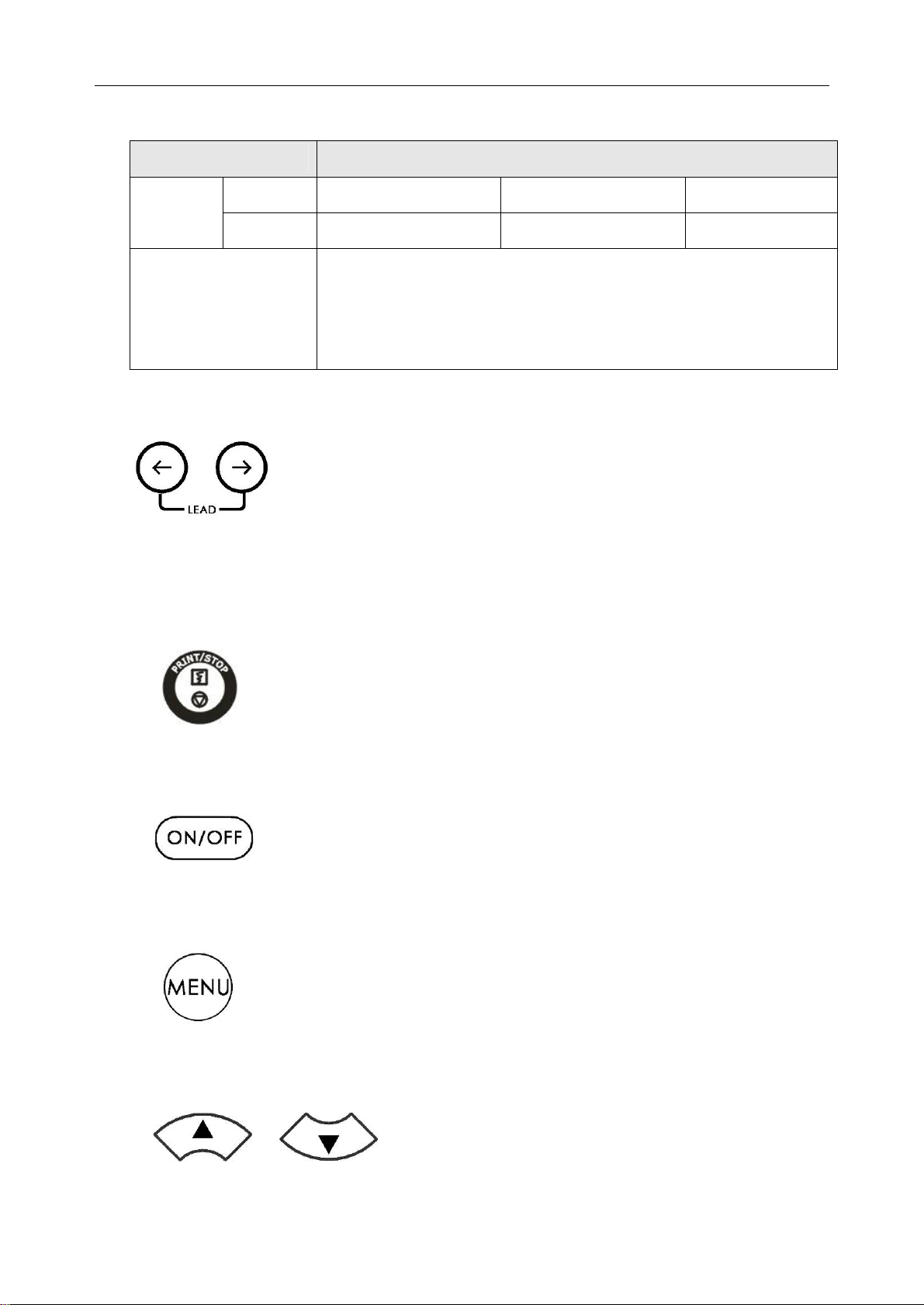
Lead switch key
Print/Stop key
ON/OFF key
Menu key
Up Arrow/Down Arrowkey
Left Arrow/ RightArrow key
Recycle
Part Number
Serial Number

VE-300 VeterinaryElectrocardiograph User Manual
-9-
Date of Manufacture
Manufacturer
Authorized Representative in the European Community
CE Mark
The symbol indicates that the device should be sent to the
special agenciesaccordingto local regulations for separate
collection after its usefullife and that this unit was put on the
market after 13 August 2005.
Rxonly(U.S.) Federal (U.S.) Law restricts this device to sale byor on the
order of a veterinarian.
VE-300 VeterinaryElectrocardiograph User Manual
-10-
3 General Information
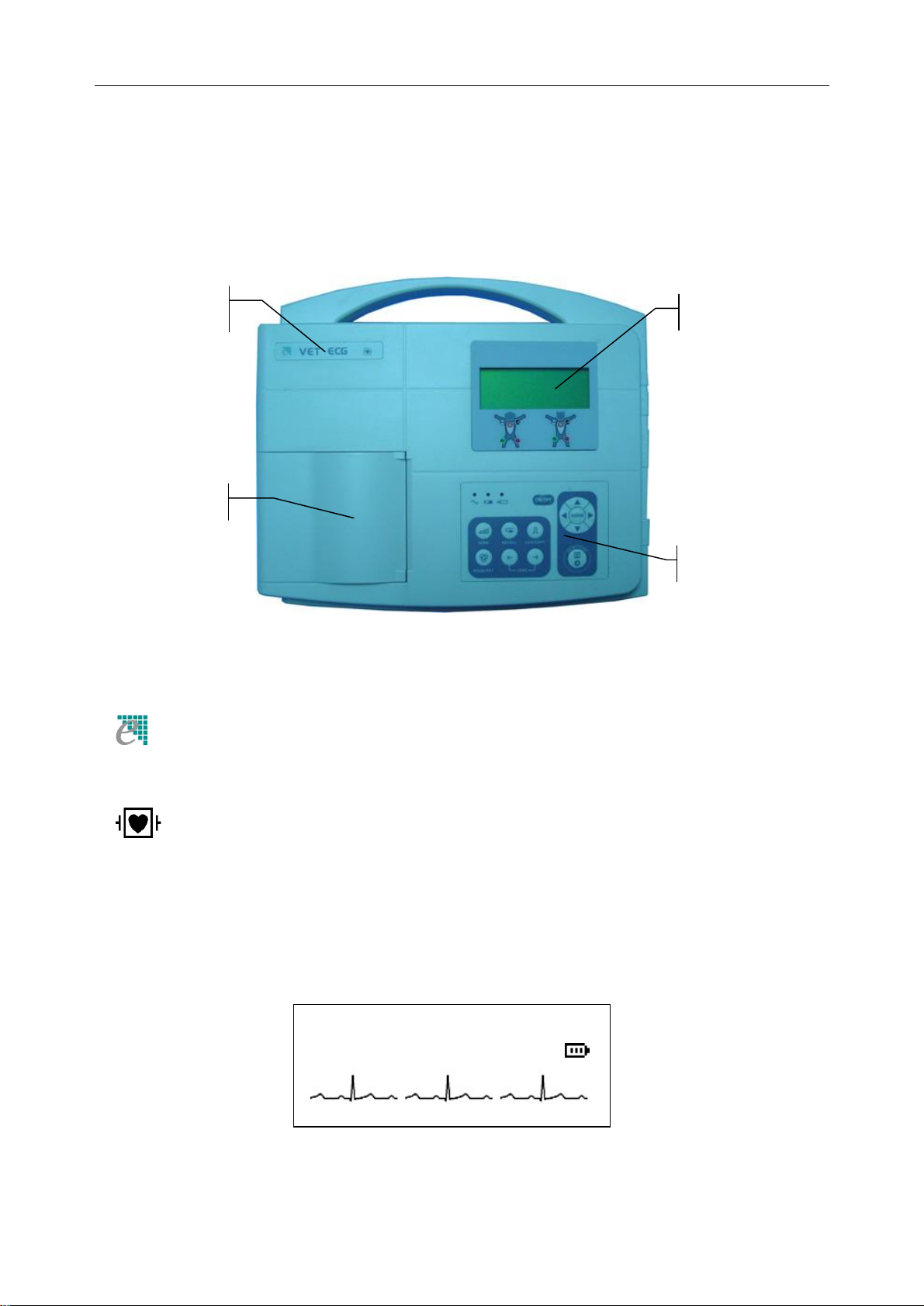
3.1 Top Panel
Figure 3-1 Main Unit
Product Information:
(Trade mark)
VETECG (Trade name)
(Classification Symbol, equipment of CF type with defibrillator proof)
3.1.1 LCD Screen
The LCD Screen specification: 192×64 dot single color LCD Screen.
Normally, the contents displayed on the LCD screen include: (descript from left to right)
AUTOPaper?M02Y
I II III 10mm/mV60
LCD Screen
Label
Recorder
Control Panel
VE-300 VeterinaryElectrocardiograph User Manual
-11-
First Row:
♦Record mode(AUTO,MANUAL, RHYTHM, USBPRTor OFF)
♦Hint information (Paper?, Printing, Sampling, Bat Weak etc.)
♦Sex(M/F) and Age
Second Row:
♦Current lead (І, П, Ш, aVR, aVL, aVF,V)
♦Sensitivity(×2.5mm/mV, ×5mm/mV, ×10mm/mV, ×20mm/mV,AGC)
♦Heart rate (Actual heart rate)
♦Batterycapacity(Onlywhen the built-in batteryis used)
Third Row:
♦ECG wave
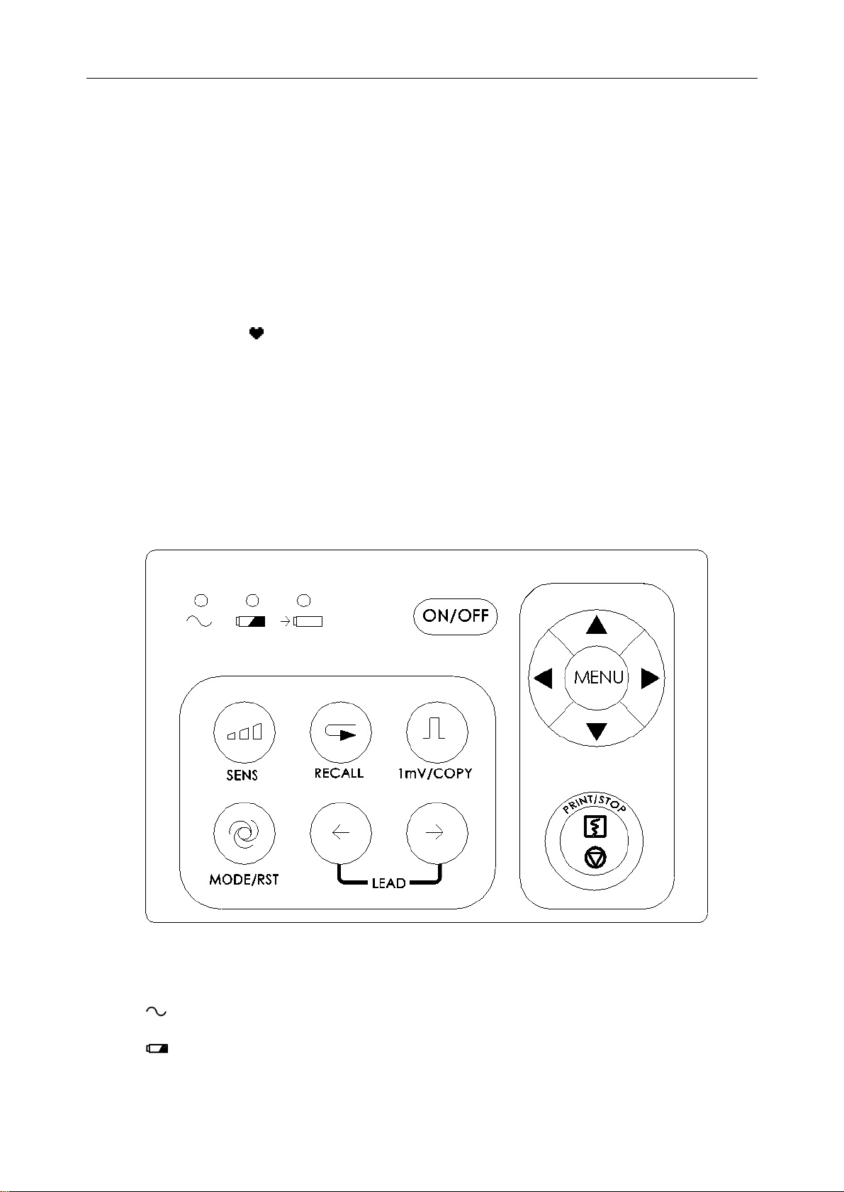
3.1.2 Control Panel and Keys
1) IndicatorLamp
Mains supplyindicator lamp: when mains supplyis used, the lamp will be lit.
Batteryindicator lamp: when the built-in rechargeable Lithium batteryisused,
the lamp will be lit.
VE-300 VeterinaryElectrocardiograph User Manual
-12-
Batteryrechargingindicator lamp: when the batteryis recharged, this lamp will
be lit.
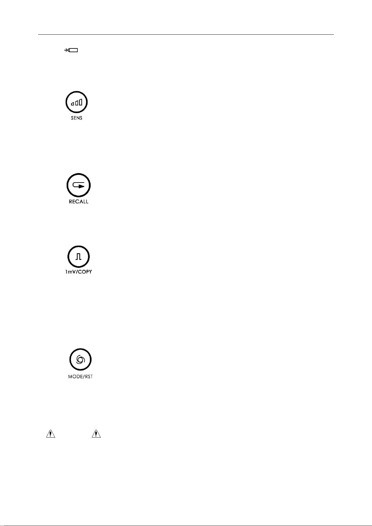
2) SENS (Sensitivity Switch Key)
The sensitivityswitchingorder: ×10 mm/mV→×20 mm/mV →AGC→×2.5 mm/mV→
×5 mm/mV.And AGC means auto gain control.
3) Recall Key
Press this keyto review the patient files saved in the recall window.
4) 1mV/COPYKey
IntheMANUALmode, this keycan be pressed to record a1mVcalibration pulse at any
time while recording.
Inthe AUTOmode, once acomplete ECG was recorded, this keycan be pressed to recall
the electrocardiogram that recorded last time.
5) MODE/RST(Mode Switch Key)
This keycan be pressedto select record mode betweenAUTO, MANUAL,RHYTHM,
USBPRTand OFF.The switchingorder of lead groups is listed in Table 3-1.
Recordingin the Manual mode, this keycan be pressed to reset the waveform quickly.
WARNING :
When using the device with defibrillator,after the defibrillator discharge, the
MODE/RSTkeyshould be pressed to reset the waveform quickly.
VE-300 VeterinaryElectrocardiograph User Manual
-13-
Table 3-1 Lead Group Switching Orderof Different Mode
Mode Switching Order(fromleft to right)
Standard
І/П/ШaVR/aVL/aVF V
AUTO
Cabrera aVL/I/-aVR II/aVF/ IIIV
MANUAL
Inthis mode, need to press Lead Switch Keyto changethe lead ,
the lead switch order can be that of AUTO(Standard)or
AUTO(Cabrera), which isdetermined bysettingsof lead sequence
and record format in the MENU
6) LEAD (Lead Switch Key)
In the MANUALmode, press the keyto switch the lead group.
In Recall window or Menu interface, this keycanbe pressed to turn the pages.
7) PRINT/STOPKey
Used to begin recordingand stop recording.
8) ON/OFFKey
When the unit has been powered on, press this keyto turn on it. Press again to turn off it.
9) MENU Key
Press this keyto enter menu settings.
10) UpArrow/Down Arrow
Pressingthe UpArroworDown Arrow can select Sexor Ageitem on the main interface.
VE-300 VeterinaryElectrocardiograph User Manual
-14-
(hereinafter called Up/Down)
During MENU setting,the two keyscanalso be pressedto selectthe item of which the
settingis to be changed.
11) LeftArrow/ Right Arrow
Press these keystochangethe content ofthe selected item.DuringMENU setting,these
keyscanalso bepressed to change the content of the selecteditem. (hereinafter called
Left/Right)
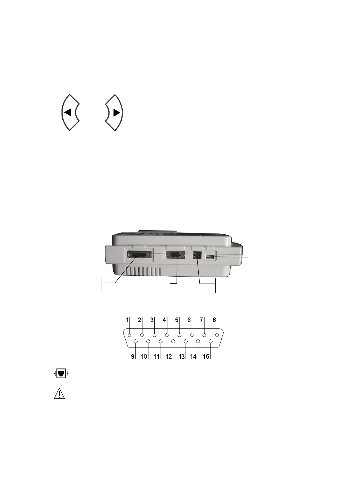
3.2 Patient Cable Socket and Signal Interface
There are sockets includingthe patient cable socket, RS232 socket, external input/output
socket and USB interface at the right side of the main unit as followingFigure shows.
1) Patient Cable Socket
:Applied part of type CF with defibrillator proof
:Attention –see accompanyingdocument
Patient Cable Socket RS232 Socket External Input/Output Socket
USB Interface
VE-300 VeterinaryElectrocardiograph User Manual
-15-
Definition of correspondingpins:
Signal Pin
Signal Pin Signal
1 NC 6 SH 11 F/LL(input)
2 NC 7 NC 12 NC
3 NC 8 NC 13 C /V(input)
4 NC 9 R /RA(input) 14 NC
5 NC 10 L/LA(input) 15 N or RF /RL(input)
Note:The left side of “/”is European standard; and the right side is American standard.
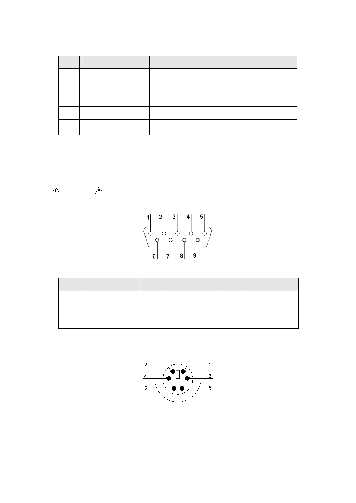
2) RS232 Socket
WARNING :RS232 interface is 1500V AC isolated intensityand the maximum
voltage applied should not exceed +15V DC.
Definition of correspondingpins:
Pin Signal Pin
Signal Pin
Signal
1 NC 4 NC 7 NC
2 RxD (input) 5 GND 8 NC
3 TxD (output) 6 NC 9 NC
3) External Input/Output Socket
Table of contents


