Edco 436 Datasheet

E-POWERTROWELS-IP-0911A
Printed in USA
TVW ©2011
Page 1
100 Thomas Johnson Drive, Frederick, MD 21702-4600 USA
Phone (301) 663-1600 • 1-800-638-3326
Fax (301) 663-1607 • 1-800-447-3326
Website: www.edcoinc.com
Email: [email protected]
Operator’s Instruction and Parts List Manual
POWER TROWELS
Manual - Portable

E-POWERTROWELS-IP-0911A
Printed in USA
©2011 TVW
Page 2
100 Thomas Johnson Drive, Frederick, MD 21702-4600 USA
Phone (301) 663-1600 • 1-800-638-3326
Fax (301) 663-1607 • 1-800-447-3326
Website: www.edcoinc.com
Email: [email protected]
READ AND UNDERSTAND THE OPERATORS INSTRUCTION MANUAL THOROUGHLY
BEFORE ATTEMPTING TO OPERATE THIS EQUIPMENT.
Death or serious injury could occur if this machine is used improperly.
Extreme care must be taken when operating electric
models with water present: Ensure power cord is prop-
erly grounded, is attached to a Ground-Fault-Interrupter
(GFI) outlet, and is undamaged.
•Check all electrical cables - be sure connections are tight and
cable is continuous and in good condition. Be sure cable is
correctly rated for both the operating current and voltage of
this equipment.
•Improper connection of the equipment-grounding conductor can
result in a risk of electric shock. Check with qualied electri-
cian or service person if there is any doubt as to whether the
outlet is properly grounded. Adhere to all local codes and
ordinances.
•NOTE: In the event of a malfunction or breakdown, grounding
provides a path of least resistance for the electric current to
dissipate. The motor is equipped with a grounded plug and
must be connected to an outlet that is properly installed and
properly grounded. DO NOT modify the plug provided on the
motor. If the plug does not t the outlet have a qualied electri-
cian install the proper receptacle.
•Switch motor OFF before disconnecting power.
•Engine exhaust from this product contains
chemicals known to the State of California to
cause cancer, birth defects or other reproduc-
tive harm.
• Gasoline is extremely ammable and poisonous.
It should only be dispensed in well ventilated areas,
and with a cool engine.
•Small gasoline engines produce high concentra-
tions of carbon monoxide (CO) example: a 5 HP 4 cycle
engine operation in an enclosed 100,000 cu. ft. area with
only one change of air per hour is capable of providing
deadly concentrations of CO in less than fteen minutes.
Five changes of air in the same area will produce noxious
fumes in less than 30 minutes. Gasoline or propane pow-
ered equipment should not be used in enclosed or partially
enclosed areas. Symptoms of CO poisoning include, head-
ache, nausea, weakness, dizziness, visual problems and
loss of consciousness. If symptoms occur - get into fresh
air and seek medical attention immediately.
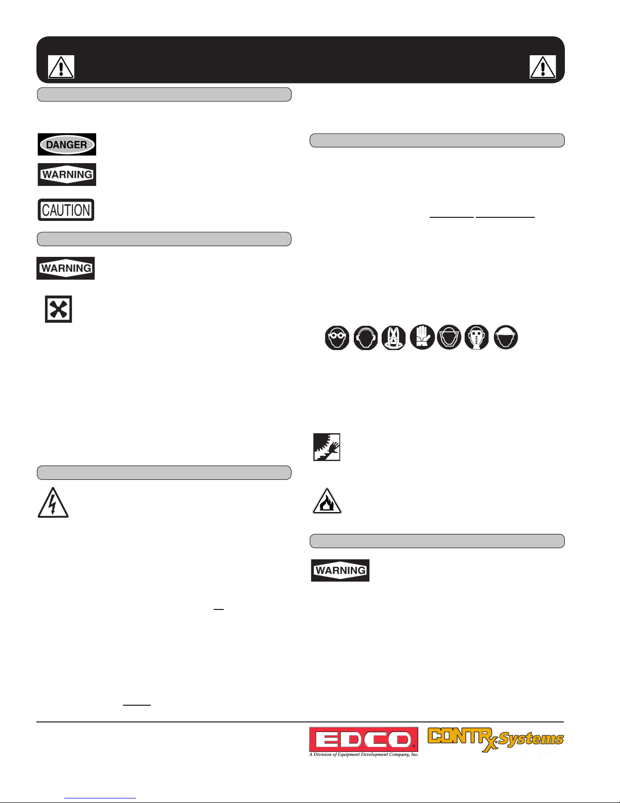
SAFETY
MESSAGES
SAFETY MESSAGES
Indicates an imminent hazard which, if not
avoided, will result in death or serious injury.
Indicates an imminent hazard which, if not
avoided, can result in death or serious injury.
Indicates hazards which, if not avoided, could
result in serious injury and or damage to the
equipment.
•Safety Instructions are proceeded by a graphic alert symbol
of DANGER, WARNING, or CAUTION.
ELECTRICAL POWERED EQUIPMENT
GASOLINE/PROPANE POWERED EQUIPMENT
•Equipment should only be operated by trained personnel in
good physical condition and mental health (not fatigued). The
operator and maintenance personnel must be physically able
to handle the bulk weight and power of this equipment.
•This is a one person tool. Maintain a safe operating distance
to other personnel. It is the operators’ responsibility to keep
other people (workers, pedestrians, bystanders, etc.) away
during operation. Block off the work area in all directions with
roping, safety netting, etc. for a safe distance. Failure to do so
may result in others being injured by ying debris or exposing
them to harmful dust and noise.
•This equipment is intended for commercial use only.
•For the operator’s safety and the safety of others, always keep
all guards in place during operation.
•Never let equipment run unattended.
•Personal Protection Equipment and proper safety attire must
be worn when operating this machinery. The operator must
wear approved safety equipment appropriate for the job such
as hard hat and safety shoes when conditions require. Hear-
ing protection MUST be used (operational noise levels of this
equipment may exceed 85db). Eye protection MUST be worn
at all times.
Keep body parts and loose clothing away from moving
parts. Failure to do so could result in dismemberment
or death.
•Do not modify the machine.
•Stop motor/engine when adjusting or servicing this equipment.
Maintain a safe operating distance from ammable
materials. Sparks from the cutting-action of this machine
can ignite ammable materials or vapors.
GENERAL INSTRUCTIONS
DUST WARNING
Some dust created by power sanding, sawing,
grinding, drilling, and other construction activi-
ties contains chemicals known to cause cancer,
birth defects, or other reproductive harm. Some
examples of these chemicals are:
•Lead from lead-based paints, and
•Crystalline silica from bricks and concrete and other
masonry products.
Your risk of exposure to these chemicals varies depending
on how often you do this type of work. To reduce your risk:
work in a well ventilated area, use a dust control system, such
as an industrial-style vacuum, and wear approved personal
safety equipment, such as a dust/particle respirator designed
to lter out microscopic particles.
•Do not disconnect power by pulling cord. To disconnect, grasp
the plug, not the cord.
•Unplug power cord at the machine when not in use and before
servicing.

E-POWERTROWELS-IP-0911A
Printed in USA
TVW ©2011
Page 3
100 Thomas Johnson Drive, Frederick, MD 21702-4600 USA
Phone (301) 663-1600 • 1-800-638-3326
Fax (301) 663-1607 • 1-800-447-3326
Website: www.edcoinc.com
Email: [email protected]
Model
“A”
“B”
“C”
Weight
446
39” (991mm)
78” (1981mm)
48” (1219mm)
238 lbs. (108kg)
EDCO POWER TROWEL
SPECIFICATIONS
Note:
All dimensions and
weights are for
reference only
and subject to change at
any time.
HOW TO ORDER REPAIR PARTS
To insure product safety and reliability, always use genuine
EDCO replacement parts when making repairs to the equip-
ment.
When ordering parts, please specify the MODEL and SERIAL
NUMBER of the machine as given on the NAMEPLATE. In
addition, give part number, description and quantity as listed
on the parts list.
Please note: Due to improvements and changes in the equip-
ment the illustrations shown may be different from the actual
machine.
Toll Free: Phone 1-800-638-3326 • Fax 1-800-447-3326
Figure 1
A
B
Section Page Number
Table of Contents
Safety Instructions.....................................................................................................2
Specications............................................................................................................3
Safety Guidelines......................................................................................................4
Operating Instructions.............................................................................................5-6
Cutting.......................................................................................................................6
SMI Dust and Silica Warning.....................................................................................6
Maintenance..............................................................................................................7
Limited Equipment Warranty..............................................................................Back Page
C
436
36” (914mm)
72” (1828mm)
38” (965mm)
226 lbs. (102kg)

E-POWERTROWELS-IP-0911A
Printed in USA
©2011 TVW
Page 4
100 Thomas Johnson Drive, Frederick, MD 21702-4600 USA
Phone (301) 663-1600 • 1-800-638-3326
Fax (301) 663-1607 • 1-800-447-3326
Website: www.edcoinc.com
Email: [email protected]
Safety Guidelines
Safety warnings and guidelines do not by themselves eliminate danger.
They are not substitutes for proper accident prevention procedures and good judgement.
Read and understand this Operator’s Instruction Manual,
and the Engine Manufacturer’s Owner’s Manual
before operating this equipment.
Death of serious injury can result if this machine is used improperly.
Eye and ear protection must be worn at all times while the saw is in use. During normal
operation, sound pressure levels exceed 85dBA. Use only ANSI approved safety glasses
to help prevent eye injury. Standard eyeglasses have only impact resistant lenses; they are
NOT safety glasses.
Operator must wear appropriate clothing and footwear. Do not wear loose clothing or jewelry
that can get tangled in moving parts. Footwear should provide sure footing and protection
from debris that may be dropped. Take steps to insure hair will not be caught in moving parts.
If necessary, tie it back.
• When loading or unloading the saw, use caution. Make sure rolling table is locked so that the blade will not be
damaged. Do not move the saw while the engine is running.
• Never exceed the maximum operating speed of the blade. Match the blade speed rating with the arbor shaft
speed.
• Never leave the saw running unattended.
• Never operate this saw under the inuence of drugs, alcohol or when taking medications that impair the senses or
reactions, or when excessively tired or under stress.
• Do not lend or rent this equipment without including the Operator’s Instruction Manual and the Engine Manufac-
turer’s Manual.
• Make sure all safety decals can be clearly read and understood. Replace damaged or missing decals immedi-
ately.
For Electric Models:
• Electric motor must be properly grounded at all times. Check the outlet box to be sure the electrical service is
properly grounded and that adequate power is available. Insufcient power will cause motor to overheat and burn
out. Use only grounded extension cords correctly sized for the current draw and voltage drop (amp rating and
length). Never use frayed, damaged, taped or underrated extension cords. Electrical shock could result in death
or serious injury and damage to the equipment.
Dry cutting creates a large volume of airborne dust. For health reasons, the operator should wear
an applicable respirator. The dust may contain chemicals known to cause serious illnesses, in-
cluding Silicosis - a fatal disease of the lungs. Check the chemical properties of the material to be
cut and follow all EPA/OSHA regulations.

E-POWERTROWELS-IP-0911A
Printed in USA
TVW ©2011
Page 5
100 Thomas Johnson Drive, Frederick, MD 21702-4600 USA
Phone (301) 663-1600 • 1-800-638-3326
Fax (301) 663-1607 • 1-800-447-3326
Website: www.edcoinc.com
Email: [email protected]
NOTICE
THE INFORMATION CONTAINED IN THIS MANUAL WAS BASED ON MACHINES IN PRODUC-
TION AT THE TIME OF PUBLICATION. EDCO RESERVES THE RIGHT TO CHANGE ANY
PORTION OF THIS MANUAL WITHOUT NOTICE.
Information Contained in this Manual:
This manual provides information and procedures to safely operate and maintain the series T364 and
T464.
For your own safety and protection from personal injury, carefully read, understand and observe the safety
instructions described in this manual.
Always operate and maintain this machine in accordance with the instructions described in this manual. A
well maintained piece of equipment will provide many years of trouble free operation.
This manual is divided into sections listed below:
Ordering Parts
This manual contains an illustrated parts list for help in ordering replacement parts for your machine.
Follow the instructions listed below when ordering parts to insure prompt and accurate delivery.
1. On all orders for service parts include the SERIAL NUMBER and MODEL NUMBER of machine.
Shipment will be delayed if this information is not included.
2. Include correct description and part number from parts section.
3. State exact shipping instructions including preferred routing and complete destination address.
4. DO NOT return parts to EDCO without rst receiving written authorization from EDCO. All authorized
returns must be shipped prepaid.
Keep this manual or a copy of it with the machine/ If you lose this manual or need an additional
copy, please contact your EDCO distributor or EDCO at 800-638-3326 or 301-663-1600.
1A
OPERATIONS
1A
OPERATIONS
2A
ASSEMBLY
3A
PARTS
1A-1

E-POWERTROWELS-IP-0911A
Printed in USA
©2011 TVW
Page 6
100 Thomas Johnson Drive, Frederick, MD 21702-4600 USA
Phone (301) 663-1600 • 1-800-638-3326
Fax (301) 663-1607 • 1-800-447-3326
Website: www.edcoinc.com
Email: [email protected]
1A
OPERATIONS
IMPORTANT REMINDER
Fill out your EDCO warranty card and place it in the mail within 24 hours of delivery.
Complete other warranty requirements as specied by the engine manufacturer in their instruc-
tions attached to the engine.
Your engine is not manufactured by EDCO, and therefore is not covered under our warranty.
Your engine manufacturer should be contacted if you wish to purchase a parts manual or a repair
manual for your engine.
Refer to the enclosed owners manual on the engine for complete Operation & Maintenance in-
structions.
Your Distributor
Your distributor has EDCO trained mechanics and original EDCO replacement parts. Always contact the
EDCO distributor who sold you this machine for EDCO certied repairs and replacement parts.
1A-3
DISTRIBUTOR NAME:____________________PHONE NUMBER:__________
ADDRESS:_______________________________________________________
CITY:________________________STATE:__________________ZIP:________
SALESMAN:______________________________________________________
ADDITIONAL INFORMATION:________________________________________
_________________________________________________________________
___________________________________________________________________________________
___________________________________________________________________________________
_________________________________________________________________
_________________________________________________________________
___________________________________________________________________________
___________________________________________________________________________
_________________________________________________________________
Place distributor information here for future reference.

E-POWERTROWELS-IP-0911A
Printed in USA
TVW ©2011
Page 7
100 Thomas Johnson Drive, Frederick, MD 21702-4600 USA
Phone (301) 663-1600 • 1-800-638-3326
Fax (301) 663-1607 • 1-800-447-3326
Website: www.edcoinc.com
Email: [email protected]
Operation Information
Model T364 and T464
1A
OPERATIONS
1A-4
Table of Contents
1.1 Safety Notes.......................................................................1A-5
1.2 Laws Pertaining to Spark Arrestors....................................1A-5
1.3 Operating Safety.................................................................1A-5
1.4 Service Safety.....................................................................1A-6
1.5 Technical Data....................................................................1A-7
1.6 Dimensions.........................................................................1A-8
1.7 Description..........................................................................1A-9
1.8 Before Starting....................................................................1A-9
1.9 Starting................................................................................1A-9
1.10 Steering...............................................................................1A-10
1.11 Pitch Adjustment..................................................................1A-10
1.12 Periodic Adjustment.............................................................1A-11
1.13 Trowel Gear Box..................................................................1A-11
1.14 Drive Belts...........................................................................1A-12
1.15 Compensation for Bent Trowel Arms...................................1A-12
1.16 Lift Lever Adjustment...........................................................1A-13
1.17 Mounting a Float Disc..........................................................1A-13
This machine was built with user safety in mind, however, it can present hazards if improperly operated and
serviced. Follow operating instructions carefully!
If you have questions about operating or servicing this equipment, please contact EDCO Customer Service
at 800-638-3326 or 301-663-1600.

E-POWERTROWELS-IP-0911A
Printed in USA
©2011 TVW
Page 8
100 Thomas Johnson Drive, Frederick, MD 21702-4600 USA
Phone (301) 663-1600 • 1-800-638-3326
Fax (301) 663-1607 • 1-800-447-3326
Website: www.edcoinc.com
Email: [email protected]
1.4 Service Safety
Poorly maintained equipment can become a safety hazard! In order for the equipment to operate safely and
properly over a long period of time, periodic maintenance and occasional repairs are necessary.
Warning
DO NOT attempt to clean or service machine while it is running. Rotating parts can cause servere
injury.
DO NOT crank a fowled engine with the spark plug removed on gasoline-powered engines. Fuel
trapped in the cylinder will squirt out of the spark plug hole.
DO NOT test for spark on gasoline-powered engines if engine is ooded or the smell of gasoline is
present. A stray spark could ignite fumes.
DO NOT use gasoline or other types of fuels or ammable solvents to clean parts, especially in en-
closed areas. Fumes from fuels and solvents can become explosive.
ALWAYS operate machine with all safety devices and guards in place and in working order.
ALWAYS keep area around mufer free of debris such as leaves, paper, cartons, etc. A hot mufer
could ignite them, starting a re.
ALWAYS replace worn or damaged components with spare parts designed and recommended by
EDCO Engineering.
ALWAYS disconnect spark plug on machines equipped with gasoline engines before servicing to
avoid accidental start up.
1A
OPERATIONS
1A-6
1.5 Technical Data
Honda Engines
Engine Make and Honda 5.5 Honda 11
Model GX160 GX340
Rated Power hp (kw) 5.5 (4.1) 11 (8.2)
Piston Displacement cu. in. (cc) 9.9 (162) 21 (344)
Spark Plug Type BPR6ES (NKG) SAME
Electrode Gap in. (mm) .029 (.75) SAME
Operating Speed RPM 3800 SAME
Fuel Capacity gal. (L) .95 (2.5) 1.6 (6.0)
Fuel Cunsumption lb/hph (g/kwh) .50 (310) .51 (310)
Running Time Hours 1.9 3.33
Centrifugal Clutch Type MECH RAMP SAME
Low Oil Shutdown Alert YES YES
Engine Oil Capacity US qt (L) .63 (.6) 1.16 (1.1)
Engine Lubrication Oil Grade SAE 10W30 SAME
Operation Weight lbs. (kg) 31 (15) 68 (31) 1A-7

E-POWERTROWELS-IP-0911A
Printed in USA
TVW ©2011
Page 9
100 Thomas Johnson Drive, Frederick, MD 21702-4600 USA
Phone (301) 663-1600 • 1-800-638-3326
Fax (301) 663-1607 • 1-800-447-3326
Website: www.edcoinc.com
Email: [email protected]
1.7 Description
The
POWER TROWEL
is a modern high production machine. Finishing rate will vary depending on opera-
tor skill and job conditions. The trowel has four nishing blades. The standard duty gearbox is designed
to provide exceptional performance low maintenance and trouble free use under the worst conditions. All
POWER TROWELS
are equipped with a safety shutdown switch and a low oil shutdown alert for added
job safety and enging protection. Operation time between fuel rells is approximately 2-1/2 to 3 hours with
rotor speeds between 80 and 120 rpm.
POWER TROWELS
are the most technically advanced trowels on
the market today. With proper maintenance and use your trowel will provide you with exceptional service.
1.8 Before Starting
Before Starting trowel check the following:
*Oil level in engine
*Oil level in trowel gear box
*Fuel level
*Condition of air lter
*Condition of trowel arms and blades
1.8 Before Starting
Before starting the operator must know the
location of all controls.
Move the choke lever to the closed
position to start the engine. The choke
may not be needed if the engine is warm
or the air temperature is hot. In this case
keep the choke lever open. Pull crank
wheel pull handle until the engine starts.
1A-9
1A
OPERATIONS

E-POWERTROWELS-IP-0911A
Printed in USA
©2011 TVW
Page 10
100 Thomas Johnson Drive, Frederick, MD 21702-4600 USA
Phone (301) 663-1600 • 1-800-638-3326
Fax (301) 663-1607 • 1-800-447-3326
Website: www.edcoinc.com
Email: [email protected]
1.10 Steering
Push down on the handle to
move the rotor assembly to the
right.
Pull up on the handle assembly
to move the rotor assembly to
the left.
1.11 Pitch Adjustment
When changing or setting the pitch of the machine be sure that the machine is at a complete stop. On ma-
chines equipped with standard pitch, turn the pitch control knob clockwise to increase the pitch and turn it
counter-clockwise to decrease the pitch. On machines equipped with positive pitch pull the pitch control
handle up to increase the pitch and push the handle down to decrease the pitch.
1A
OPERATIONS
1A-10
1.12 Periodic Maintenance Schedule
The chart below lists basic engine maintenance. Refer to engine manufacturer’s Operation Manual for ad-
ditional information on engine maintenance. A copy of the engine Operator’s Manual was supplied with the
machine when it was shipped.
1.13 Trowel Gearbox
Check gearbox sight glass for correct oil level daily (every 8 hours). Add oil if oil level is below the bottom
third of the sight glass. The gearbox oil level should only be checked when the gearbox is in the level posi-
tion. To add oil, tilt trowel back and remove sight glass. Add oil through sight glass opening. Replace sight
glass and check oil level. Do NOT ll past the 3/4 full point. Use only Mobil oil SHC 634, ISO Grade 460,
Medium SAE 140 weight.
DAILY EVERY 50
HOURS
EVERY 100
HOURS
EVERY 300
HOURS
GREASE TROWEL ARMS
CHECK OIL LEVEL IN GEARBOX
CHECK FUEL FILTER
INSPECT AIR FILTERS - REPLACE AS NEEDED
CHECK AND TIGHTEN EXTERNAL HARDWARE
CHECK AND ADJUST DRIVE BELTS
CHANGE ENGINE OIL
REPLACE FUEL FILTER
REPLACE SPARK PLUG
1A-11
√
√
√
√
√
√
√
√
√
√
√
√
√
√
√
√
√
√

E-POWERTROWELS-IP-0911A
Printed in USA
TVW ©2011
Page 11
100 Thomas Johnson Drive, Frederick, MD 21702-4600 USA
Phone (301) 663-1600 • 1-800-638-3326
Fax (301) 663-1607 • 1-800-447-3326
Website: www.edcoinc.com
Email: [email protected]
1.14 Drive Belts
To Replace Belts:
1. Remove belt guard (A) by removing the four belt guard mounting bolts (B). See Figure 1.
2. Rotate the pulley (C) while pulling the bottom of the belt (D) out. See Figure 2.
3. After the belt (D) has cleared the pulley, remove it from clutch (E). See Figure 3.
4. Repeat steps 1 through 3 in reverse order to install new belt.
NOTE: When replacing the belt be sure that the pulley and the clutch are in perfect alignment. If the belt
is allowed to lean to the left or right it will cause the clutch to engage prematurely on start-up.
1.15 Compensating for Bent Trowel Arms
1. Loosen nut (B) slightly.
2. Adjust bolt (A) until trowel blade is level.
3. Tighten nut.
(See gure 4)
1A
OPERATIONS
1A-12

E-POWERTROWELS-IP-0911A
Printed in USA
©2011 TVW
Page 12
100 Thomas Johnson Drive, Frederick, MD 21702-4600 USA
Phone (301) 663-1600 • 1-800-638-3326
Fax (301) 663-1607 • 1-800-447-3326
Website: www.edcoinc.com
Email: [email protected]
1.16 Lift Lever Adjustment
Damage to, or replacement of, a trowel arm can change the
adjustment of the lift lever. This can unbalance the trowel
arms and cause the trowel to wobble during operation. To
operate smoothly, the lift lever on all arms must be adjusted
equally. All arms should be adjusted at the same time to
ensure that the trowel is balanced correctly. Adjust trowel
arms using optional adjusting tool as described below.
1. Block up pressure plate using wooden blocks (b) and
have blades without contact.
2. Loosen hex head screws (a) on spider which secures
trowel arm in place (do not remove screws).
3. Remove trowel arms from spider with lift levers in place
4. Remove blade from trowel arms.
5. Clean all ats on trowel arm before placing it in the
adjusting tool (c) to make sure it lies at. Clean thor-
oughly using a wire brush and scraper.
6. The adjusting tool comes with three different size spacers.
Use the shortest spacer (d) when adjusting the T364 and
T464. Use the medium spacer when adjusting the T464SD.
7. Insert trowel arm into adjusting tool as shown.
8. Tighten socket head bolts (e) down on the trowel arm to
hold it in place.
9. Move adjusting tool arm (f) over carriage bolts (g) on lift
levers shown.
10. Loosen the jam nut (h) and adjust the carriage bolt so
that the top of the bolt is just touching and making contact
with the bottom of the adjusting tool.
11. Tighten jam nut to secure adjustment in place.
12. Attach blades to arms and trowel arms to spider plate.
Tighten hex head screws to secure arm in spider.
1.17 Mount Floating Disc
Certain applications may require the use of a oating disc.
To mount disc (a), lift trowel off the ground (engine off) and
position disc against blades. Turn disc either to the right or
the left to engage clip angles (b) as shown. Remember the
right hand trowel blades turn counter-clockwise the left-hand
blades turn clockwise.
1A
OPERATIONS
1A-13

E-POWERTROWELS-IP-0911A
Printed in USA
TVW ©2011
Page 13
100 Thomas Johnson Drive, Frederick, MD 21702-4600 USA
Phone (301) 663-1600 • 1-800-638-3326
Fax (301) 663-1607 • 1-800-447-3326
Website: www.edcoinc.com
Email: [email protected]
ASSEMBLY INSTRUCTIONS
STEP 1: Un-pack the handle assembly (A) and the lower
unit from their boxes. Check to make sure no damage was
done during shipment. Mount the handle assembly (A) to
the gearbox (B) on the lower unit using 4 3/8” nylock nuts
(C) that are supplied in a package in the lower unit.
STEP 2: With the handle mounted to the lower unit, attach
the pitch control cable (A) through the yoke arm (B) using
the remaining 3/8” nylock nut (C). Tighten the nylock nut to
where there is approximately a 1/4” of the threads are
showing.
STEP 3: Attach the kill wire (A) that is coming from the
handle assembly to the engine using the wire splicer (B)
that is supplied on the lower unit.
STEP 4: Make sure that the throttle lever on the handle
assembly is pushed all the way forward. Remove the
breather cap and the breather from the engine. Unscrew
the cable adjustment clasp (A). Next make sure that the
throttle lever (B) on the engine is pushed all the way forward .
Insert the wire coming out of the cable into the hole (C)
shown on the diagram. With everything in place, put the
cable adjustment clasp (A) back on and tighten down snug.
2A-1
2A
ASSEMBLY

E-POWERTROWELS-IP-0911A
Printed in USA
©2011 TVW
Page 14
100 Thomas Johnson Drive, Frederick, MD 21702-4600 USA
Phone (301) 663-1600 • 1-800-638-3326
Fax (301) 663-1607 • 1-800-447-3326
Website: www.edcoinc.com
Email: [email protected]
Parts Information
INFORMATION...............................................................PAGE(S)
Lower End Assembly........................................................3A-2 & 3
Handle Assembly..............................................................3A-4
Pitch Control Assembly.....................................................3A-5
Standard Gearbox Assembly............................................3A-6 & 7
Standard Fan Cooled Gearbox Assembly.........................3A-8 & 9
Kill Switch Assembly.................................................... .....3A-10
Speed Kits (Low & High)...................................................3A-11
Optional Accessories.........................................................3A-12
3A
PARTS
3A-1
NOTES:

E-POWERTROWELS-IP-0911A
Printed in USA
TVW ©2011
Page 15
100 Thomas Johnson Drive, Frederick, MD 21702-4600 USA
Phone (301) 663-1600 • 1-800-638-3326
Fax (301) 663-1607 • 1-800-447-3326
Website: www.edcoinc.com
Email: [email protected]
LOWER END ASSEMBLY
3A-2
43 SERIES BLADES
PICTURED ABOVE
3A
PARTS
43A
43B
43C
43E
43F
43D
43 SERIES BLADES

E-POWERTROWELS-IP-0911A
Printed in USA
©2011 TVW
Page 16
100 Thomas Johnson Drive, Frederick, MD 21702-4600 USA
Phone (301) 663-1600 • 1-800-638-3326
Fax (301) 663-1607 • 1-800-447-3326
Website: www.edcoinc.com
Email: [email protected]
3A-3
3A
PARTS
ILL. PART# DESCRIPTION QTY
1 . . . . . . 037619 . . . . . RING, T364. . . . . . . . . . . . 1
. . . . . . 037626 . . . . . RING, T464. . . . . . . . . . . . 1
2 . . . . . . 221480 . . . . . LIFTING HOOK . . . . . . . . .1
3 . . . . . . 018961 . . . . . ENGINE, 5.5 HO . . . . . . . .1
. . . . . . 033395 . . . . . ENGINE, 5.5 KA . . . . . . . . 1
. . . . . . 018957 . . . . . ENGINE, 11 HO . . . . . . . . .1
. . . . . . 033397 . . . . . ENGINE, 11 KA . . . . . . . . . 1
4 . . . . . . KEY SUPPLIED WITH ENGINE. . . . . . . . 1
5 . . . . . . 016604 . . . . . CLUTCH, 3/4” . . . . . . . . . . 1
. . . . . . 015701 . . . . . CLUTCH 1” . . . . . . . . . . . . 1
6 . . . . . . 010083 . . . . . FLAT WASHER . . . . . . . . . 1
7 . . . . . . 010090 . . . . . LOCK WASHER . . . . . . . . 1
8 . . . . . . 022553 . . . . . BOLT . . . . . . . . . . . . . . . . . 1
9 . . . . . . 010100 . . . . . NUT . . . . . . . . . . . . . . . . . . 4
10 . . . . . 010090 . . . . . LOCK WASHER . . . . . . . . 4
11 . . . . . 010082 . . . . . FLAT WASHER . . . . . . . . . .4
12 . . . . . 018012 . . . . . STUD . . . . . . . . . . . . . . . . . 4
13 . . . . . 010039 . . . . . BOLT . . . . . . . . . . . . . . . . . .4
14 . . . . . 037648 . . . . . RUBBER BUSHING . . . . . .4
15 . . . . . 037665 . . . . . MTR MNT RH 11 HP . . . . . 1
. . . . . 037656 . . . . . MTR MNT RH 5 HP . . . . . . 1
16 . . . . . 037675 . . . . . FLAT WASHER . . . . . . . . . .4
17 . . . . . 010464 . . . . . NUT . . . . . . . . . . . . . . . . . . .4
18 . . . . . 015711 . . . . . SCREW . . . . . . . . . . . . . . . .4
19 . . . . . 010273 . . . . . KEY, 3/16 X 2 . . . . . . . . . . . 1
20 . . . . . 015707 . . . . . PULLEY . . . . . . . . . . . . . . . 1
20a . . . . 012784 . . . . . PULLEY (used on 040973
. . . . . . . . . . . . . . . . . & 040974) . . . . . . . . . . . . . . 1
21 . . . . . 015202 . . . . . GEARBOX . . . . . . . . . . . . . .1
. . . . . 040969 . . . . . SFC GEARBOX
. . . . . . . . . .
1
22 . . . . . 020977 . . . . . GUARD BRACKET . . . . . . . 1
23 . . . . . 037661 . . . . . MTR MNT LH11 HP . . . . . . .1
. . . . . 037659 . . . . . MTR MNT LH 5 HP . . . . . . . 1
24 . . . . . 015987 . . . . . SMALL GUARD . . . . . . . . . .1
. . . . . 015703 . . . . . LARGE GUARD . . . . . . . . . .1
25 . . . . . 012753 . . . . . STAR WASHER . . . . . . . . . .4
26 . . . . . 010002 . . . . . BOLT . . . . . . . . . . . . . . . . . . 2
27 . . . . . 010019 . . . . . BOLT . . . . . . . . . . . . . . . . . . 2
28 . . . . . 010090 . . . . . LOCK WASHER . . . . . . . . . .2
29 . . . . . 015677 . . . . . E-CLIP . . . . . . . . . . . . . . . . . 2
30 . . . . . 015678 . . . . . YOKE ARM PIN . . . . . . . . . . 1
31 . . . . . 015683 . . . . . BOLT . . . . . . . . . . . . . . . . . . .4
32 . . . . . 015682 . . . . . STAR WASHER . . . . . . . . . . 4
33 . . . . . 016920 . . . . . TROWEL ARM CLIP . . .. . ..4
34 . . . . . 015816 . . . . . 4-BOSS . . . . . . . . . . . . . . . . 1
35 . . . . . 015684 . . . . . NUT . . . . . . . . . . . . . . . . . . . 8
36 . . . . . 012990 . . . . . BOLT . . . . . . . . . . . . . . . . . . 4
37 . . . . . 015686 . . . . . BOLT . . . . . . . . . . . . . . . . . . 4
38 . . . . . 010022 . . . . . BOLT . . . . . . . . . . . . . . . . 4
39 . . . . . 010024 . . . . . BOLT . . . . . . . . . . . . . . . . 4
LOWER END ASSEMBLY (cont’d)
ILL. PART# DESCRIPTION QTY
40 . . . . . 010090 . . . . . LOCK WASHER . . . . . . . 8
41 . . . . . 015688 . . . . . INSERT . . . . . . . . . . . . . . 4
42 . . . . . 015818 . . . . . T364 TROWEL ARM . . . . 4
. . . . . . 024794 . . . . . T464 “ “ . . . . 4
43A. . . . 40050-C . . . . F-1C FINISH TROWEL
. . . . . . . . . . . . . . . . .BLADE 6x14 . . . . . . . . . . . 4
43B. . . . 40060-C . . . . M-1C FLOAT TROWEL
. . . . . . . . . . . . . . . . BLADE 10x14 (SLIPS
. . . . . . . . . . . . . . . . .OVER FINISH BLADE) . . .4
43C. . . . 40040-C . . . . C-1C COMBINATION
. . . . . . . . . . . . . . . . . TROWEL BLADE 8x14 . . .4
43D. . . . 40080-C . . . . F-3C FINISH TROWEL
. . . . . . . . . . . . . . . . . BLADE 6x18 . . . . . . . . . . .4
43E. . . . 40090-C . . . . M-3C FLOAT TROWEL
. . . . . . . . . . . . . . . . . BLADE 10x18 . . . . . . . . . .4
43F. . . . 40070-C . . . . C-3C COMBINATION
. . . . . . . . . . . . . . . . . TROWEL BLADE 8x18. . . 4
44 . . . . . 017264 . . . . . YOKE ARM . . . . . . . . . . . .1
45 . . . . . 015821 . . . . . PRESSURE CAP . . . . . . .1
46 . . . . . 015822 . . . . . THRUST BEARING . . . . . 1
47 . . . . . 015824 . . . . . PRESSURE PLATE . . . . .1
48 . . . . . 015696 . . . . . KEY, 1/4 X 1-1/4 . . . . . . . .1
49 . . . . . 015893 . . . . . T364 SPIDER ASS’Y. . . . 1
. . . . . . 024812 . . . . . T464 “ “ . . . . 1
50 . . . . . 015690 . . . . . WASHER . . . . . . . . . . . . . 1
51 . . . . . 015691 . . . . . BOLT . . . . . . . . . . . . . . . . 1
52 . . . . . 041325 . . . . . BELT, T364, T464. . . . . . . 1
52a. . . . .041353 . . . . . 11/13 LO SPEED . . . . . . . 1
53 . . . . . 036665 . . . . . SPACER . . . . . . . . . . . . . .1
. . . . . . 039407 . . . . . SPACER . . . . . . . . . . . . . .1
54 . . . . . 033032 . . . . . LIFT LEVER . . . . . . . . . . . 4
. . . . . . 033034 . . . . . LIFT LEVER . . . . . . . . . . . 4
55 . . . . . 039203 . . . . . UPPER RING (T364) . . . . 1
56 . . . . . 037265 . . . . . WHEEL HOUSING . . . . . . 4
57 . . . . . 037422 . . . . . RETAINING SPACER. . . . 4
58 . . . . . 037269 . . . . . PIN . . . . . . . . . . . . . . . . . . 4
59 . . . . . 037267 . . . . . BEARING . . . . . . . . . . . . . 8
60 . . . . . 039204 . . . . . LOWER RING (T364). . . . 1
61. . . . . 039211 . . . . . URETHANE BELT
. . . . . . . . . . . . . . . . . (T364)111” . . . . . . . . . . . . .1
62 . . . . . 012974 . . . . . 5/16-24 X 3/4 BOLT . . . . . .4
63 . . . . . 010090 . . . . . LOCK WASHER . . . . . . . . 2
64 . . . . . 010082 . . . . . FLAT WASHER . . . . . . . . . 2
65 . . . . . 015693 . . . . . PLUG . . . . . . . . . . . . . . . . .1
66 . . . . . 015694 . . . . . PLUG . . . . . . . . . . . . . . . . .4
. . . . . . 015694 . . . . . PLUG -- (T464) . . . . . . . . . 12
67 . . . . . 041681 . . . . . COVER, LH (T364) . . . . . . 2
68 . . . . . 041683 . . . . . COVER, RH (T364). . . . . . 2
69 . . . . . 040860 . . . . . BRACKET . . . . . . . . . . . . . 4
70 . . . . . 020542 . . . . . NUT, 1/4” STOVER . . . .. . 16
71 . . . . . 015805 . . . . . STAB. RING (T464). . . . . . 1

E-POWERTROWELS-IP-0911A
Printed in USA
TVW ©2011
Page 17
100 Thomas Johnson Drive, Frederick, MD 21702-4600 USA
Phone (301) 663-1600 • 1-800-638-3326
Fax (301) 663-1607 • 1-800-447-3326
Website: www.edcoinc.com
Email: [email protected]
3A-4
3A
PARTS
ILL. PART# DESCRIPTION QTY
1 . . . . . 037668 . . . . . GRIP . . . . . . . . . . . . . . . . . . . . . 2
2 . . . . . 015724 . . . . . HNDLASSY FINE PITCH LG. . .1
. . . . . . 015725 . . . . . HNDLASSY FINE PITCH ST . . .1
. . . . . . 028012 . . . . . HNDLASSY POS PITCH LG . . .1
. . . . . . 034449 . . . . . HNDLASSY POS PITCH ST . . .1
. . . . . . 020498 . . . . . HNDL ST WELD’T F/PT . . . . . . 1
. . . . . . 020499 . . . . . HNDL LG WELD’T F/PT . . . . . .1
3 . . . . . 015739 . . . . . KNOB. ADJ. HANDLE . . . . . . . .1
4 . . . . . 015740 . . . . . PIN, SPIRAL 3/16 X 1-3/4 . . . . .1
5 . . . . . 015741 . . . . . SCREW, SHAFT . . . . . . . . . . . .1
6 . . . . . 015743 . . . . . BUSHING . . . . . . . . . . . . . . . . . 1
7 . . . . . 015746 . . . . . BUSHING, SLIDE . . . . . . . . . . .1
8 . . . . . 018409 . . . . . SWITCH, SAFETY ASSY . . . . .1
9 . . . . . 015736 . . . . . LEVER, THROTTLE . . . . . . . . .1
10 . . . . 015410 . . . . . SET SCREW 1/4-20 X 3/8 . . . . 1
11 . . . . 013370 . . . . . SCREW, 10-32 X 3/8 . . . . . . . . 2
12 . . . . 015769 . . . . . BAR, CARRY . . . . . . . . . . . . . . 1
13 . . . . 011238 . . . . . NUT, NYLOCK 1/2-13 . . . . . . . .2
14 . . . . 015754 . . . . . PIN, 3/8 X 1-3/8 . . . . . . . . . . . . 1
15 . . . . 015753 . . . . . PULLEY CABLE . . . . . . . . . . . .1
16 . . . . 015752 . . . . . BLOCK, CABLE SUPPORT . . . 1
17 . . . . 034714 . . . . . BRKT, MTG. F/SHT HNDL . . . . 1
. . . . . . 034201 . . . . . BRKT, MTG. F/LNG HNDL . . . . 1
18 . . . . 010075 . . . . . FSTN, 1/2-13 X 3 GR. 5 . . . . . . 2
19 . . . . 015735 . . . . . THROTTLE CABLE ASSY . . . . 1
ILL. PART# DESCRIPTION QTY
21 . . . . . 016691 . . . . . CABLE, FINE SHORT . . . . . . .1
. . . . . . . 015748 . . . . . CABLE, FINE LONG . . . . . . . .1
21A . . . . 027952 . . . . . CABLE LEVER PITCH ASSY .1
21B . . . . 028013 . . . . . CABLE 44.25” POSITIVE
. . . . . . . . . . . . . . . . . . .PITCH SHORT HANDLE . . . . 1
22 . . . . . 015742 . . . . . BEARING . . . . . . . . . . . . . . . . 1
23 . . . . . 034441 . . . . . INSULATION F/HANDLE . . . . 1
24 . . . . . 034440 . . . . . COVER, F/ HANDLE BAR . . . 1
25 . . . . . 010004 . . . . . FSTN. 1/4-20 X 1-1/4 . . . . . . . 4
26 . . . . . 034279 . . . . . BLOCK, ADJ HANDLE . . . . . .1
27 . . . . . 034282 . . . . . HANDLE, ADJUSTABLE . . . . .1
28 . . . . . 034283 . . . . . HNDL FINE PITCHADJ (LG) . 1
. . . . . . . 034284 . . . . . HNDL FINE PITCHADJ (SH) . 1
. . . . . . . 034450 . . . . . HNDL POS PITCHADJ (LG) . 1
. . . . . . . 034451 . . . . . HNDL POS PITCHADJ (SH) . .1
29 . . . . . 010089 . . . . . FSTN 1/4 LW . . . . . . . . . . . . . .4
30 . . . . . 015744 . . . . . WASHER . . . . . . . . . . . . . . . . .1
31 . . . . . 015747 . . . . . ROLL PIN . . . . . . . . . . . . . . . . 1
32 . . . . . 015745 . . . . . RING, RETAINING . . . . . . . . . 1
33 . . . . . 034285 . . . . . EXT. F/ LONG HANDLE . . . . . 1
. . . . . . . 034286 . . . . . EXT. F/ SHORT HANDLE . . . . 1
HANDLE ASSEMBLY

E-POWERTROWELS-IP-0911A
Printed in USA
©2011 TVW
Page 18
100 Thomas Johnson Drive, Frederick, MD 21702-4600 USA
Phone (301) 663-1600 • 1-800-638-3326
Fax (301) 663-1607 • 1-800-447-3326
Website: www.edcoinc.com
Email: [email protected]
3A-5
3A
PARTS
ILL. PART# DESCRIPTION QTY
1 . . . . . 019247 . . . . . KNOB, BURLOP PLASTIC 1-7/8 . . . . . . . . . . 1
2 . . . . . 036448 . . . . . HANDLE, POSITIVE PITCH . . . . . . . . . . . . . .1
3 . . . . . 010002 . . . . . BOLT, 1/4-20 x 3/4 . . . . . . . . . . . . . . . . . . . . . .3
4 . . . . . 010081 . . . . . FLAT WASHER, 1/4 . . . . . . . . . . . . . . . . . . . . .3
5 . . . . . 027963 . . . . . COVER, WELD’T LEVER PITCH. . . . . . . . . . .1
6 . . . . . 027958 . . . . . CLUTCH, POS PITCH ASSY . . . . . . . . . . . . . 1
7 . . . . . 018510 . . . . . GREASE FITTING 1/4-28 x 45º . . . . . . . . . . . 1
8 . . . . . 032346 . . . . . NUT, 3/8 FLEX LOCK PLAIN . . . . . . . . . . . . . 1
9 . . . . . 027946 . . . . . SPROCKET, LEVER PITCH . . . . . . . . . . . . . . 1
10 . . . . 015813 . . . . . KEY, 3/16 x 1 . . . . . . . . . . . . . . . . . . . . . . . . . .1
11 . . . . 028033 . . . . . CHAIN, #35 R/V . . . . . . . . . . . . . . . . . . .3.25 in
12 . . . . 028013 . . . . . CABLE, POS PITCH CONTROL (SHORT) . . .1
. . . . . . 027952 . . . . . CABLE, POS PITCH CONTROL (LONG) . . . . 1
13 . . . . 010019 . . . . . BOLT, 5/16-18 x 3/4 GR. 5 . . . . . . . . . . . . . . . .2
14 . . . . 024630 . . . . . BUSHING, FLANGE . . . . . . . . . . . . . . . . . . . . 1
15 . . . . 027948 . . . . . BUSHING, SUPPORT BRACKET . . . . . . . . . .1
16 . . . . 027961 . . . . . BRKT. LEVER PITCH CLUTCH . . . . . . . . . . . 1
17 . . . . 010100 . . . . . NUT, HEX 5/16-18 . . . . . . . . . . . . . . . . . . . . . .2
18 . . . . 010090 . . . . . LOCKWASHER, 5/16 . . . . . . . . . . . . . . . . . . . 4
19 . . . . 010018 . . . . . BOLT, 5/16-18 x 1/2 GR. 5 . . . . . . . . . . . . . . . 2
20 . . . . 010081 . . . . . FSTN, 1/4 LW . . . . . . . . . . . . . . . . . . . . . . . . . 3
21 . . . . 028035 . . . . . LINK, MASTER (BOTH ENDS) . . . . . . . . . . . .2
PITCH CONTROL ASSEMBLY

E-POWERTROWELS-IP-0911A
Printed in USA
TVW ©2011
Page 19
100 Thomas Johnson Drive, Frederick, MD 21702-4600 USA
Phone (301) 663-1600 • 1-800-638-3326
Fax (301) 663-1607 • 1-800-447-3326
Website: www.edcoinc.com
Email: [email protected]
GEARBOX ASSEMBLY
3A-6
3A
PARTS

E-POWERTROWELS-IP-0911A
Printed in USA
©2011 TVW
Page 20
100 Thomas Johnson Drive, Frederick, MD 21702-4600 USA
Phone (301) 663-1600 • 1-800-638-3326
Fax (301) 663-1607 • 1-800-447-3326
Website: www.edcoinc.com
Email: [email protected]
3A-7
3A
PARTS
GEARBOX ASSEMBLY (cont’d)
ILL. PART# DESCRIPTION QTY
1 . . . . . . 015205 . . . . . . . . . . SCREW, 5/16-18 x 1 . . . . . . . . . . . . . . . . . . . . . . . . . . . . . . 8
2 . . . . . . 015209 . . . . . . . . . . VALVE, 1/8 NPT-27 RELIEF . . . . . . . . . . . . . . . . . . . . . . . . 1
3 . . . . . . 015208 . . . . . . . . . . COVER, GEARBOX MACHINED . . . . . . . . . . . . . . . . . . . . 1
4 . . . . . . 032772 . . . . . . . . . . SHIM, (.002) . . . . . . . . . . . . . . . . . . . . . . . . . . . . . . AS REQ.
. . . . . . . 020018 . . . . . . . . . . SHIM, (.003) . . . . . . . . . . . . . . . . . . . . . . . . . . . . . . AS REQ.
. . . . . . . 015210 . . . . . . . . . . SHIM, (.005) . . . . . . . . . . . . . . . . . . . . . . . . . . . . . . AS REQ.
5 . . . . . . 015212 . . . . . . . . . . SCREW, 3/8-16 x 1 (LH) . . . . . . . . . . . . . . . . . . . . . . . . . . . .1
6 . . . . . . 015213 . . . . . . . . . . WASHER, PRESSURE . . . . . . . . . . . . . . . . . . . . . . . . . . . . .1
7 . . . . . . 022073 . . . . . . . . . . BEARING, TAPERED ROLLER . . . . . . . . . . . . . . . . . . . . . . 1
. . . . . . . 022074 . . . . . . . . . . BEARING RACE . . . . . . . . . . . . . . . . . . . . . . . . . . . . . . . . . .1
8 . . . . . . 015216 . . . . . . . . . . GEAR, BRONZE (RH) . . . . . . . . . . . . . . . . . . . . . . . . . . . . . .1
9 . . . . . . 015217 . . . . . . . . . . BEARING, RADIAL BALL . . . . . . . . . . . . . . . . . . . . . . . . . . . 1
10 . . . . . 015219 . . . . . . . . . . SHAFT, MAIN MACH. FINISHED . . . . . . . . . . . . . . . . . . . . . 1
11 . . . . . 015696 . . . . . . . . . . KEY, 1/4 x 1-1/4 HARDENED . . . . . . . . . . . . . . . . . . . . . . . . 1
12 . . . . . 015660 . . . . . . . . . . O-RING, GEARBOX END CAPS . . . . . . . . . . . . . . . . . . . . . 1
13 . . . . . 015222 . . . . . . . . . . SHIM, (.005) . . . . . . . . . . . . . . . . . . . . . . . . . . . . . . AS REQ.
. . . . . . . 015186 . . . . . . . . . . SHIM, (.003) . . . . . . . . . . . . . . . . . . . . . . . . . . . . . . AS REQ.
14 . . . . . 017314 . . . . . . . . . . BOLT, 1/4-20 x 5/8 . . . . . . . . . . . . . . . . . . . . . . . . . . . . . . . . .4
15 . . . . . 015221 . . . . . . . . . . CAP, GEARBOX END (4-HOLE) . . . . . . . . . . . . . . . . . . . . . .1
16 . . . . . 010498 . . . . . . . . . . PLUG,3/8 NPT BI SQUARE HD PIPE . . . . . . . . . . . . . . . . . .1
17 . . . . . 015672 . . . . . . . . . . SIGHTGLASS, 3/4-14 NPT . . . . . . . . . . . . . . . . . . . . . . . . . . 1
18 . . . . . 015673 . . . . . . . . . . O-RING . . . . . . . . . . . . . . . . . . . . . . . . . . . . . . . . . . . . . . . . . 1
19 . . . . . 015204 . . . . . . . . . . GEARBOX, MACHINE FINISHED . . . . . . . . . . . . . . . . . . . . .1
20 . . . . . 015671 . . . . . . . . . . SEAL, OIL CR# 13650 . . . . . . . . . . . . . . . . . . . . . . . . . . . . . .1
21 . . . . . 012953 . . . . . . . . . . PLUG, 3/4 NPT BI SQUARE HD PIPE . . . . . . . . . . . . . . . . . 1
22 . . . . . 015662 . . . . . . . . . . NUT, JAM LH 5/8-18 . . . . . . . . . . . . . . . . . . . . . . . . . . . . . . . 1
23 . . . . . 015663 . . . . . . . . . . BEARING, ANGULAR CONTACT . . . . . . . . . . . . . . . . . . . . .1
24 . . . . . 022025 . . . . . . . . . . SPACER, FIBER GEARBOX COUNTERS . . . . . . . . . . . . . .1
25 . . . . . 026740 . . . . . . . . . . SHAFT, INPUT RH GEARBOX . . . . . . . . . . . . . . . . . . . . . . .1
26 . . . . . 015668 . . . . . . . . . . BEARING, TAPERED ROLLER . . . . . . . . . . . . . . . . . . . . . . 1
. . . . . . . 015669 . . . . . . . . . . BEARING RACE . . . . . . . . . . . . . . . . . . . . . . . . . . . . . . . . . .1
27 . . . . . 015660 . . . . . . . . . . O-RING, GEARBOX ENDCAPS . . . . . . . . . . . . . . . . . . . . . .1
28 . . . . . 015222 . . . . . . . . . . SHIM, (.005) . . . . . . . . . . . . . . . . . . . . . . . . . . . . . . AS REQ.
. . . . . . . 015186 . . . . . . . . . . SHIM, (.003) . . . . . . . . . . . . . . . . . . . . . . . . . . . . . . AS REQ.
29 . . . . . 015223 . . . . . . . . . . FLANGE, GEARBOX (4-HOLE) . . . . . . . . . . . . . . . . . . . . . . 1
30 . . . . . 017314 . . . . . . . . . . BOLT, 1/4-20 x 5/8 . . . . . . . . . . . . . . . . . . . . . . . . . . . . . . . . .4
31 . . . . . 015670 . . . . . . . . . . SEAL, OIL SEAL CR# 7443 . . . . . . . . . . . . . . . . . . . . . . . . . 1
Note: Items 4, 13 and 28 from above are sold only a kit.
SHIM SET - 029457
This kit consists of (2) 015210, (2) 015222,
(2) 020018, and (2) 022186.
This manual suits for next models
1
Table of contents
Popular Trowel manuals by other brands

MAKER
MAKER MT36-4 operating instructions

Euro Shatal
Euro Shatal ST 122 Operating instructions/spare parts list

Schwamborn
Schwamborn BEG 90 Translation of the original operating manual

Beton Trowel
Beton Trowel BT405 instruction manual

MULTIQUIP
MULTIQUIP Whiteman series Operation manual

Belle
Belle 600X Operator's manual