EDELRID FLEX LITE User manual

FLEX LITE

Abb. / fig. / ill. / afb. / fig. / rys.
1a C
D
H
A
E
E
F
H

I
K
J
B
G
1b
2a
3a
2b
3b
2c
3c

4a
4b
5a 5b 5c
5d 5e
6a 6b
6c 6d 6e

5 min
5 min
7a 7b
A
EN 361:
2002
A/2
EN 361:
2002
8b8a
9a 9b 9c
8c 8d 8e
40°C 40°C
10a
11
10b
max. +55 °C
min. –20 °C
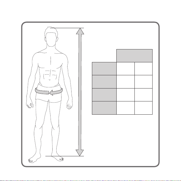
Flex Lite
Zertifizierung
Certification EN 361 EN 361
Größe
Size S – M L – XL
Gewicht
Weight 1.100 g 1.190 g
Körpergröße
Body Size 155 – 180 cm 175 – 205 cm
12
13
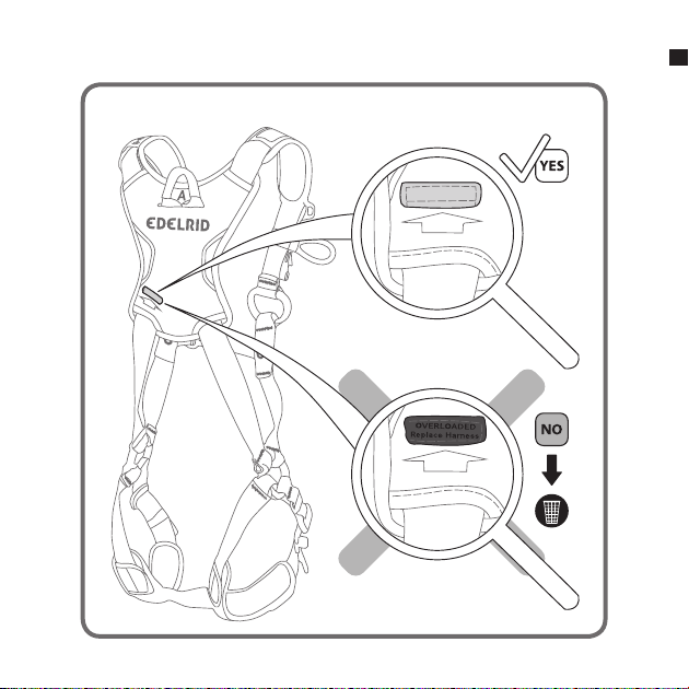
FALL INDICATOR
FALL INDICATOR
DE

Flex Lite
Fall Arrest Harness according to EN 361, ANSI/
ASSE Z359.11-2014
INSTRUCTIONS FOR USAGE, SAFETY,
LIFESPAN, STORAGE AND CARE
This product is part of personal protective equipment
for protection (PPE) against falls from heights and
should be allocated to one individual.
These instructions for use contain important notes,
a control card and a proof of inspection (test book).
Before using this product, all documents must have
been read and their content understood. This
document must be provided to the user by the
retailer in the respective country’s language and
must be kept with the equipment while it is in use.
INSTRUCTIONS FOR USE
These instructions must be carefully read and
followed. This product especially manufactured
for working at great heights or depths does not
release users from the risk borne personally.
Work and sporting activities carried out at great
heights or depths are potentially dangerous. Errors
and carelessness can lead to serious injuries or
even to death. Experience is required in order to
select the correct equipment. Equipment may only
be used by trained and experienced persons or
under instruction and supervision. Users must be
aware that poor physical and/or mental health can
jeopardise safety under normal conditions and in
emergencies. The manufacturer cannot be held
liable if the equipment has been abused or used
incorrectly. In all cases, the users or the persons
responsible bear the responsibility and the risk.
When using this product in the areas of rescuing
and personal protective equipment, we recommend
that the relevant national regulations be observed.
EN
Before using the equipment, the user must
ensure that, in the event of falling into the
PPE-system, the person caught can be rescued
immediately, safely and effectively. Motionless
suspension in a harness may cause severe injury
and even death (suspension trauma) Personal
protection equipment products may only be
used to belay people.
Product specific notes
Fig. 1a/b designations of relevant elements:
A Sternal catch eye EN 361
B Dorsal catch eye EN 361
C Adjustable shoulder straps/Easy Glider buckle
D Tear-off/freely positionable equipment
attachment loop up to max. 5 kg
E Triple Lock buckle
F Removable leg cushion
G Fall indicator
H Elastic keepers
I Individual labelling field
J Bag for RFID (chip)
K Labelling
Application to EN 361 (Fig. 8a – e):
The harness is safely connected to a rescue or fall
arrest system at the catch eyes (A or A/2); the
connectors employed (karabiners should
withstand a lateral force of ≥ 15 kN) must
conform to EN 362 and are fastened to the catch
eyes (marked A or A/2). When using the front
catch eyes A/2 both eyes must be attached to the
connector conforming to EN 362. Catch systems
may be used with or without energy absorbing
elements. In case of a fall, the fall arrest systems
must reduce the fall arresting force to a value
that can be born by the human body (6 kN).

EN
Only one fall arrest harness to EN 361 may be
used in each fall arrest system! Before using a
fall arrest system, ensure that sufficient free
room for a fall from the work position is
available below the user.
Free room for fall below the user
The elongation (Hs) of the harness upon a fall
load is max. 27 cm. Observe the corresponding
instructions supplied with the lanyard (energy
absorbing lanyards, height securing devices,
guided-type fall arresters on movable or
stationary guide) as well as those of other
components that may be used.
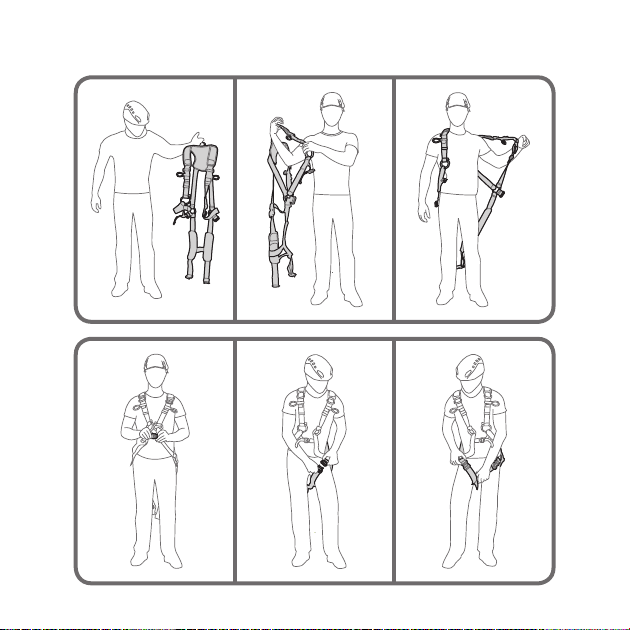
Fig. 2 Putting on of the harness
2a Aligning the harness to the shoulder cushion
2b – c Putting the harness on laterally (like a
jacket)
Fig. 3a – c When closing the Triple Lock buckles
on the legs and the hip be sure to assign them
correctly. Note the marking! (Legs – left & right)
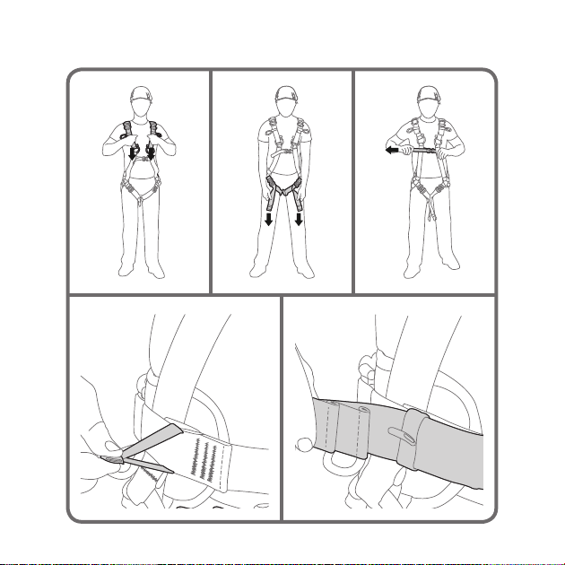
Fig. 4 Use of different buckle types
4a On TripleLock buckles flip the frame up to
attach it to the hook. To loosen the buckle, force
the frame into the buckle housing and lift the
buckle up at the same time.
4b To loosen EasyGlider buckles flip them up.
To close, pull the outbound webbing. Pull the
covers over the buckles upon closing.
Fig. 5 a – c Tightening the shoulder, leg and
breast straps
Fig. 5 d – e Stowing the excess strapping in the
strap keeper
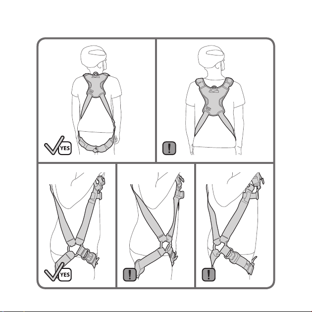
Fig. 6
6a The shoulder cushion should align flush with
the nape of the neck.
6b Shoulder cushion too low
6c – e Position of the textile hip joint
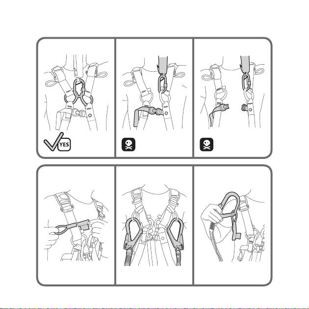
Fig. 9 Equipment attachment loops
9a Free positioning
9b Stowage for lanyards to EN 354, EN 355
9c Detach if the load exceeds 5 kg
Fig. 7 Upon adjustment but before using the
harness you should try being suspended in it for
at least 5 minutes in the planned usage situation.
The harness must fit comfortably. When
properly selected (Fig. 12 size table) and
adjusted the suspension test must not result in
hindered breathing and/or pain. When the
harness has been applied, its metal parts should
not contact genitals or arm pits. Free suspension
in the harness must not lead to excessive arching
of the back, tensioning of the body, pressure on
the genitals, loins or arm pits. Women's
lymphatic vessels of the breast should not be
constricted if at all possible.
ANCHOR POINT
In order to avoid high loads and swinging falls
in the event of a fall, anchor points for belay
purposes must always be as vertical as possible
above the person to be belayed. The lanyard/
anchor device from the anchor point to the
person secured should always be kept as taut as
possible. Slack ropes must be avoided! The
anchor point must be designed in such a way
that, when fixing the PPE, no effects can occur
which reduce the stability and it is not damaged
during use.

Sharp edges, ridges and crushing can
seriously impair the stability. These should be
covered, where necessary, using suitable
auxiliary equipment. The anchor point and the
anchoring must be able to withstand the
expected loads in a worst-case scenario. Even if
energy absorbers (to EN 355) are used, the
anchor points must be specified for a fall
arresting force of up to 10 kN, also refer to EN
795
When using a lanyard (fall arrest system), please
note that the maximum overall length of the
lanyard including shock absorbers and
connecting components must not exceed 2.0m.
SAFETY NOTICES
When combining this product with other
components, the safety aspects of the
products may interfere with each other.
If this product is used in combination with
other components of a rescue/fall arrest
system, users must acquaint themselves with
the enclosed recommendations, notes and
instructions for these components prior to
use and comply with them. This equipment
should only be used in connection with parts
of personal protective equipment (PPE)
bearing the CE-symbol to protect individuals
against falls from heights.
If original components are modified or
removed from the product, its safety aspects may
be restricted. The equipment should not be
modified in any way or altered to allow
attachment of additional parts without the
manufacturer’s written recom-mendation.
The equipment must be checked for possible
damage before and after each use. It must be
ensured that the equipment is serviceable and
fully functional.
The equipment must be discarded immediately
if there is even the slightest doubt as to its
serviceability.
WARNING! The products must be kept away
from damaging environments. This includes
contact with abrasive and aggressive
substances (e.g. acids (battery acid!), alkalis,
soldering water, oils, cleaning agents), as well
as extreme temperatures and flying sparks.
In addition, sharp edges, wetness and especially
icing-up can diminish the stability of textiles.
CLIMATE REQUIREMENTS Fig. 10b
The permanent use temperature of the product
(in dry condition) ranges from approx. -20°C to
+55°C.
LIFESPAN AND REPLACEMENT
The lifespan of the product mainly depends
mainly on the way and frequency in which it
is used and external influences.
Products made from synthetic fibre (polyamide,
polyester, dyneema) are subject to a certain
ageing process even if they are not used. This is
caused by the intensivity of UV-rays and
environmental influences.
The maximum service life at optimum storage
conditions (see item Storage) and with no use is
12 years.
The maximum service life (commercial/non-
commercial use) assuming proper use, no visible
signs of wear, and at optimum storage
conditions is 10 years.

PPE showing signs of wear must be replaced, for
instance, if the edges of webbing and straps are
damaged, if fibres have come off the webbing, if
seams are damaged or show signs of wear, or if the
equipment has come in contact with chemicals.
Watch out for sharp burrs or signs of corrosion on
metal parts of the equipment. Repairs may only be
performed as outlined in the instructions of the
manufacturer.
In case of extreme use (extreme signs of wear), for
instance, upon strain by a fall or when damage is
visible, immediately remove the PPE from use and
turn it over to the manufacturer or a competent
person for inspection and/or repair; be sure to
request a written confirmation for the work done
(Fig. 13).
Repairs may only be performed as outlined in the
instructions of the manufacturer.
INSPECTION
The product must be checked and, if necessary,
maintained whenever this is necessary but at least
yearly by the manufacturer, an expert or an
authorised testing centre.
In the process, it must be ensured among other
things that the product labelling is legible.
When the maximum service life of 10 years has been
reached, the PPE must be removed from further use.
STORAGE, TRANSPORT AND CARE
Storage
Store in a cool, dry, dark place outside transport
containers. Avoid contact with chemicals (caution:
battery acid!) Store without mechanical stress
caused by jamming, pressure or tension.
Transport
The product must be kept away from direct sunlight,
chemicals, dirt and mechanical damage. For this
purpose, a protective bag or special storage and
transport containers should be used.
purpose, a protective bag or special storage
and transport containers should be used.
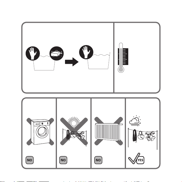
Cleaning Fig. 10a and 11
Clean soiled products in luke-warm water (if
neces-sary, use pH-neutral soap). Rinse well. Dry
at room temperature, never use a tumble drier or
dry close to radiators! If required, halogen-free
commercial disin-fectants may be used.
If required, hinges of metal parts may be oiled
after cleaning.
WARNING! Failure to follow these
instructions may endanger life!
Material:
- Polyamide
- Polyester
- Aluminium
- Steel
INFORMATION ON THE PRODUCT:
Manufacturer: EDELRID
Product description:
Fall arrest harness according to EN 361,
ANSI/ASSE Z359.11
Model: Flex Lite
Size
Maximum user load
YYYY MM: Year and month of manufacture
Lot number: GV xxx xxxx
Identification: (to be entered by the user him/
herself if appropriate)
CE 0123: certification body monitoring the PPE
production
i-Symbol: Warning notices and instructions
must be read and observed
Fall arrest harness to EN 361: Marking A and
A/2 (A/2 + A/2 = A ): catch eye

Declaration of Conformity:
EDELRID GmbH & Co. KG herewith declares that the
article is in conformity with the applicable pertinent
requirements and regulations of the EU Directive
89/686 applicable until 20 April 2018 and of the EU
Regulation 2016/425 applicable as off 21 April 2018.
The original declaration of conformity may be
downloaded from the following website:
http://www.edelrid.de/...
Remarks
Instructions for use: CE XXXX: Notified body responsible
for issuing of the EC Type Approval Certificate of the
product.
Our products are manufactured with the utmost care.
However, should any of our products give cause for a
justified complaint, please advise us of the lot number.
We reserve the right to make technical amendments.
ANSI additional information
- The Instructions for Use must be provided to the user
of this equipment.
- The Instructions for Use for each item of equipment
used in conjunction with this product must be followed.
- Rescue plan: You must have a rescue plan and the
means to rapidly implement it in case of difficulties
encountered while using this equipment.
- WARNING: when using multiple items of equipment, a
dangerous situation can arise in which the safety function
of an item of equipment can be af-fected by the safety
function of another item of equipment.
- WARNING: chemicals, heat, corrosion and ultravio-let
light can damage your harness. Contact Edelrid if there is
any doubt about the condition of this product.
- Be vigilant when working near sources of
electricity, moving machinery or abrasive or sharp
surfaces.
Appendix A – ANSI/ ASSE Z359.11
ANSI/ASSE Z359 Requirements for proper use and
maintenance of full body harnesses
Note: these are general requirements and
information provided by ANSI/ASSE Z359; The
manufacturer of this equipment may impose more
stringent restrictions on the use of the products they
manufacture, see the manufacturer’s instructions.
1. It is essential that the users of this type of
equipment receive proper training and instruction,
including detailed procedures for the safe use of
such equipment in their work application. ANSI/
ASSE Z359.2, minimum requirements for a
managed fall protection program, establishes
guidelines and requirements for an employer’s
managed fall protection program, including policies,
duties and training, fall protection procedures,
eliminating and controlling fall hazards, rescue
procedures, incident investigations and evaluating
program effectiveness.
2. Correct fit of a full body harness is essential to
proper performance. Users must be trained to select
the size and maintain the fit of their full body
harness.
3. Users must follow manufacturer’s instructions for
proper fit and sizing, paying particular attention to
ensure that buckles are connected and aligned
correctly, leg straps and shoulder straps are kept
snug at all times, chest straps are located in the
middle chest area, and leg straps are positioned and
snug to avoid contact with the genitalia should a fall
occur.

4. Full body harnesses which meet ANSI/ASSE
Z359.11 are intended to be used with other
components of a personal fall arrest system that limit
maximum arrest forces to 1800 pounds (8 kN) or less.
5. Suspension intolerance, also called suspension
trauma or orthostatic intolerance, is a serious condi-
tion that can be controlled with good harness design,
prompt rescue, and post fall suspension relief devices.
A conscious user may deploy a suspension relief
device allowing the user to remove tension from
around the legs, freeing blood flow, which can delay
the onset of suspension intolerance. An attachment
element extender is not intended to be attached
directly to an anchorage or anchorage connector for
fall arrest. An energy absorber must be used to limit
maximum arrest forces to 1800 pounds (8 kN). The
length of the attachment element extender may
affect free fall distances and free fall clearance cal-
culations.
6. Full body harness (FBH) stretch, the amount the
FBH component of a personal fall arrest system will
stretch and deform during a fall, can contribute to
the overall elongation of the system in stopping a fall. It
is important to include the increase in fall distance
created by FBH stretch, as well as the FBH connector
length, the settling of the user’s body in the FBH, and
all other contributing factors when calculating total
clearance required for a particular fall arrest system.
7. When not in use, unused lanyard legs that are still
attached to a full body harness D-ring should not be
attached to a work positioning element or any other
structural element on the full body harness unless
deemed acceptable by the competent person and
manufacturer of the lanyard. This is especially im-
portant when using some types of Y-style lanyards, as
some [dangerous shock] load may be transmitted to
the user through the unused lanyard leg if it is not
able to release from the harness. The lanyard parking
attachment is generally located in the sternal area to help
reduce tripping and entanglement hazards.
8. Loose ends of straps can get caught in machinery or cause
accidental disengagement of an adjuster. All full body
harnesses shall include keepers or other components which
serve to control the loose ends of straps.
9. Due to the nature of soft loop connections, it is
recommended that soft loop attachments only be used to
connect with other soft loops or carabiners. Snap hooks
should not be used unless approved for the application by
the manufacturer. Sections 10-16 provide additional
information concerning the location and use of various
attachments that may be provided on this FBH.
10. Dorsal
The dorsal attachment element shall be used as the primary
fall arrest attachment, unless the application allows the use of
an alternate attachment. The dorsal attachment may also be
used for travel restraint or rescue. When supported by the
dorsal attachment during a fall, the design of the full body
harness shall direct load through the shoulder straps
supporting the user, and around the thighs. Supporting the
user, post fall, by the dorsal attachment will result in an
upright body position with a slight lean to the front with
some slight pressure to the lower chest. Considerations
should be made when choosing a sliding versus fixed
dorsal attachment element. Sliding dorsal attachments are
generally easier to adjust to different user sizes, and allow a
more vertical rest position post fall, but can increase FBH
stretch.
11. Sternal
The sternal attachment may be used as an alternative fall
arrest attachment in applications where the dorsal
attachment is determined to be inappropriate by a
competent person, and where there is no chance to fall in
a direction other than feet first.

Accepted practical uses for a sternal attachment
include, but are not limited to, ladder climbing with a
guided type fall arrestor, ladder climbing with an
overhead self-retracting lifeline for fall arrest, work
positioning, and rope access. The sternal attachment
may also be used for travel restraint or rescue. When
supported by the sternal attachment during a fall, the
design of the full body harness shall direct load
through the shoulder straps supporting the user, and
around the thighs. Supporting the user, post fall, by
the sternal attachment will result in roughly a sitting
or cradled body position with weight concentrated on
the thighs, buttocks and lower back. Supporting the
user during work positioning by the sternal
attachment will result in an approximate upright body
position. If the sternal attachment is used for fall
arrest, the competent person evaluating the
application should take measures to ensure that a fall
can only occur feet first. This may include limiting the
allowable free fall distance. It may be possible for a
sternal attachment incorporated into an adjustable
style chest strap to cause the chest strap to slide up
and possibly choke the user during a fall, extraction,
suspension... The competent person should consider
full body harness models with a fixed sternal
attachment for these applications.
12. Frontal
The frontal attachment serves as a ladder climbing
connection for guided type fall arrestors where there is
no chance to fall in a direction other than feet first, or
may be used for work positioning. Supporting the
user, post fall or during work positioning, by the
frontal attachment will result in a sitting body
position, with the upper torso upright, with weight
concentrated on the thighs and buttocks. When
supported by the frontal attachment, the design of the
full body harness shall direct load directly around the
thighs
and under the buttocks by means of the subpelvic
strap. If the frontal attachment is used for fall
arrest, the competent person evaluating the
application should take measures to ensure that a
fall can only occur feet first. This may include
limiting the allowable free fall distance.
13. Shoulder: The shoulder attachment elements
shall be used as a pair, and are an acceptable attach-
ment for rescue, and entry/retrieval. The shoulder
attachment elements shall not be used for fall arrest.
It is recommended that the shoulder attachment
elements be used in conjunction with a yoke
which incorporates a spreader element to keep
the full body harness shoulder straps separated.
14. Waist, rear: The waist, rear attachment shall
be used solely for travel restraint. The waist, rear
attachment element shall not be used for fall arrest.
Under no circumstances is it acceptable to use the
waist, rear attachment for purposes other than
travel restraint. The waist, rear attachment shall
only be subjected to minimal loading through the
waist of the user, and shall never be used to
support the full weight of the user.
15. Hip: The hip attachment elements shall be
used as a pair, and shall be used solely for work
positioning. The hip attachment elements shall not
be used for fall arrest. Hip attachments are often
used for work positioning by arborists, utility
workers climbing poles, and construction workers
tying rebar and climbing on form walls. Users are
cautioned against using the hip attachment
elements (or any other rigid point on the full body
harness) to store the unused end of a fall arrest
lanyard, as this may cause a tripping hazard, or, in
the case of a multiple-leg lanyard, could cause
adverse loading to the full body harness and the
wearer through the unused portion of the
lanyard.

16. Suspension seat: The suspension seat attachment
elements shall be used as a pair, and shall be used
solely for work positioning. The suspension seat
attachment elements shall not be used for fall arrest.
Suspension seat attachments are often used for
prolonged work activities where the user is
suspended, allowing the user to sit on the suspension
seat formed between the two attachment elements. An
example of this use would be window washers on
large buildings.
USER INSPECTION, MAINTENANCE AND
STOR-AGE OF EQUIPMENT
Users of personal fall arrest systems shall, at a
minimum, comply with all manufacturer instructions
regarding the inspection, maintenance and storage of
the equipment. The user’s organization shall retain
the manufacturer’s instructions and make them
readily available to all users. See ANSI/ASSE
Z359.2, Minimum requirements for a managed fall
protection program regarding user inspection,
maintenance and storage of equipment.
1. In addition to the inspection requirements set forth
in the manufacturer’s instructions, the equipment
shall be inspected by the user before each use and,
additionally, by a competent person, other than the
user, at interval of no more than one year for:
- absence or illegibility of markings
- absence of any elements affecting the equipment
form, fit or function
- evidence of defects in or damage to hardware
elements including cracks, sharp edges, deformation,
corrosion, chemical attack, excessive heating, al-
teration and excessive wear
- evidence of defects in or damage to strap or ropes
including fraying, unsplicing, unlaying, kinking,
knotting, roping, broken or pulled stitches, excessive
elongation, chemical attack, excessive soiling,
abrasion, alteration, needed or excessive lubrication,
excessive aging and excessive wear
2. Inspection criteria for the equipment shall be set
by the user’s organization. Such criteria for the
equipment shall equal or exceed the criteria
established by this standard or the manufacturer’s
instructions, whichever is greater.
3. When inspection reveals defects in, damage to, or
inadequate maintenance of equipment, the
equipment shall be permanently removed from
service or undergo adequate corrective
maintenance, by the original equipment
manufacturer or their designate, before return to
service.
Maintenance and storage
1. Maintenance and storage of equipment shall be
conducted by the user’s organization in accordance
with the manufacturer’s instructions. Unique issues,
which may arise due to conditions of use, shall be
addressed with the manufacturer.
4. Equipment which is in need of, or scheduled for
maintenance shall be tagged as “unusable” and
removed from service.
5. Equipment shall be stored in a manner as to
preclude damage from environmental factors such as
temperature, light, UV, excessive moisture, oil,
chemicals and their vapors or other degrading
elements.
Table of contents
Languages:
Other EDELRID Protection Device manuals

Popular Protection Device manuals by other brands


Val-Matic
Val-Matic VentSafe Security Cage Operation, maintenance and installation manual

ABB
ABB RET630 Product guide

ELAC
ELAC PB62-W Setup guide

Husqvarna
Husqvarna HP500BT-01 Operator's manual

Max-Air Systems
Max-Air Systems ME G Series Installation, operation and maintenance instructions

PSP
PSP ZAP Light Extreme quick start guide


